Numerical Study on Flow and Heat Transfer Characteristics Inside Rotating Rib-Roughened Pipe with Axial Throughflow
2023-11-22,,,
,,,
College of Energy and Power, Nanjing University of Aeronautics and Astronautics, Nanjing 210016, P.R.China
Abstract: A numerical study was performed on the flow and heat transfer characteristics inside a rotating ribroughened pipe with an axial throughflow, under a fixed axial throughflow Reynolds number Rex 6 400 and a series of rotational Reynolds number Reω ranging from 0 to 3.77×10⁴.Three rib configurations were taken into consideration,including ring rib, discrete-ring rib and longitudinal rib, wherein the ring-type ribs were distributed along the axial direction and the longitudinal-type ribs were distributed along the circumferential direction.The results show that the flow field inside a rotating pipe is affected by both axial through flow and rotation-induced azimuthal flow.Under small rotational Reynolds numbers, the axial through flow is dominant such that the ring-type rib plays significant heat transfer enhancement role.Whereas under high rotational Reynolds numbers, the rotation-induced azimuthal flow is dominant such that the longitudinal-type rib is superior to the ring-type rib on heat transfer enhancement.In the view of a comprehensive performance factor that considers both heat transfer enhancement and flow loss together, the discrete-ring rib is identified to be the best among the current three rib configurations under small rotational Reynolds numbers.However, under high rotational Reynolds numbers, the ring-type ribs show no advantage over smooth pipe, and even lead to a reduction in comprehensive performance when compared to the smooth pipe.For the highspeed rotating pipe, the longitudinal-type rib is a promising rib configuration as applied to the heat transfer enhancement.
Key words:rotating pipe; rib configuration; axial throughflow; flow and heat transfer; comprehensive performance factor
0 Introduction
The hydrodynamic gas bearing utilizes the gas dynamic pressure compression effect to provide rigid rotor bearing capacity.As it owns some inherent advantages, such as self-acting, no requirements of external pressurization and lubricant supply, and low-cost maintenance, the hydrodynamic gas bearing has been widely applied in the airborne electricmachine system and turbomachineary[1].To satisfy the technological advancement of airborne electricmachine system and turbomachineary towards more compact size and greater efficiency, the rotational speed needs further prompted such that the thermal effects on the performance of foil journal bearings will significantly behave in the practical applications, due to the strong viscous-shearing inside the thin hydrodynamic gas film[2-4].Apparently the thermal management becomes one of the quite challenging subjects in the ultra-high speed journal bearings.
Considering that the natural cooling scheme to remove the heat generation inside the hydrodynamic gas film is crucially limited, the use of additional forced cooling is a significant necessity for avoiding impervious degradation and even thermal damage of ultra-high speed journal bearings[5].During past decades, a lot of efforts were devoted to the thermal management of hydrodynamic foil journal bearings.Refs.[6-7] proposed two cooling schemes for the radial gas foil bearings, such as the axial throughflow cooling scheme by forcing the cooling air through the film layer axially and air injection cooling scheme by supplying the cooling air into the film layer radially from feeding holes.Ref.[8] proposed a hybrid cooling scheme, wherein two cooling air flow paths were designed, referring as the outer cooling flow that flows through the gas film and foil gap, and the inner cooling flow that flows through the hollow shaft.Ref.[9] performed laboratory tests to identify the aerodynamics of foil bearing under hot surroundings with the use of axial cooling flow.Ref.[10] performed an investigation on the design of the cooling flow passage for the gas foil bearings used in the micro gas turbines.Ref.[11] performed an experimental and theoretical investigation on the thermal behavior of a hybrid bump-metal foil bearing.Different thermal managements with cooling air flows in hollow rotor and bearing substructure were considered and the heat-carrying ratios between two cooling air flows.From aforementioned works, it was exactly sure that the outer cooling flow through the gas film and foil gap played a dominant role on the heat removal of the heat generation inside hydrodynamic gas film.However, the pressure drop inside the outer cooling flow channel was dramatically increased with the increase of operational speed,such that the throughflow capacity was seriously affected in the high-speed operational situations.Therefore, the inner cooling inside a hollow shaft was essential for controlling the temperature rise of rotor.
In the viewing of fundamental flow dynamics,the flow inside a hollow shaft is reasonably modeled as a classical internal flow inside a rotating pipe with an axial throughflow.With respect to the stationary situation, the flow structure inside a rotating pipe is significantly altered by the centrifugal force caused by the rotation, generally leading to a convective heat transfer enhancement but also a stronger pressure drop[12-15].For the rotating pipes, the installedrib turbulator is still an effective means for enhancing the convective heat transfer coefficient, following the same principle as that in the stationary pipes[16-18].To the best of our knowledge, the transverse rib or circular ring-type rib is the main configuration as applied to the stationary pipes, wherein multiple ring-type ribs are distributed along the axial direction to introduce the secondary flow and cause the flow separation and reattachment[19-21].Discrete ribs have the ability to interrupt the continuous development of the buoyancy layer near the wall,which can reduce the negative effect of buoyancy and enhance heat transfer to a certain extent[22-24].However, for the circular pipe that rotates about its axis, as the internal flow field is featured by a helicoidal flow structure caused by the superposing of rotation-induced zimuthal movement on the axial through flow, whether the ring-type rib plays the same role on heat transfer enhancement as that in the stationary situation is doubted.In particular,when the rotational speed is high enough the rotation-induced Zimuthal movement is dominate in the internal flow, the flow disturbance role of transverse ribs to the internal helical flow in the rotating situation is conjectured to be changed with respect to the stationary situation.Therefore the rib configuration has significant effects on the internal flow and heat transfer of a rotating pipe with an axial throughflow, which is still lack of deeper identification.
The objective of the present investigation is to assess the effects of rib configuration on the flow and heat transfer inside a rotating rib-roughened pipe with an axial throughflow, by using a numerical methodology.Three rib configurations, including ring-type rib, discrete ring-type rib and longitudinal-type rib, are taken into consideration under a fixed axial-throughflow Reynolds number and a series of rotational Reynolds numbers.From current study, the influences of rotational speed or rotational Reynolds number on the pressure drop and convective heat transfer coefficient are illustrated.In particular, reasonable rib configurations are proposed in accordance with the rotational conditions,in the viewing of the comprehensive performance factor.
1 Physical Model and Simplifications
A typical bump-type hydrodynamic foil journal bearing consists of shaft, foil assembly and bearing sleeve, as schematically shown in Fig.1.
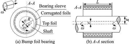
Fig.1 Schematic diagram of hydrodynamic gas bearing structure
During the operation, a self-acting offset of the rotor from the global bearing center is formed, with an eccentricity between the shaft and the bearing sleeve.The hydrodynamic pressure effect of the lubricating gas itself is built up in an eccentric circular gap around the circumference of the bearing, to provide the bearing capacity.Meanwhile, the heat generation inside the hydrodynamic gas film occurs due to the strong viscous heating effect.Considering the current study concerns the internal flow and heat transfer inside a rotating hollow shaft, a researched physical model is taken, as schematically displayed in Fig.2, wherein the supporting section in hydrodynamic foil journal bearing (L=25 mm) is simplified as the heating section by imposing a fixed heat load.In this physical model, the main geometric parameters are denoted as the follows: the radius of shaftR=10.95 mm, the inner diameter of rotating tubed=15 mm, the thickness of tubeb=3.45 mm.The front section relative to the heating section has a length ofLe=20 mm and rear section has a length ofLc=45 mm.In order to enhance the heat transfer capacity inside the rotating tube, the rib-roughened turbulators are installed.Three rib configurations are considered, referring as ring-type rib(RT)(Fig.2(a)), discrete ring-type rib(DRT) (Fig.2(b)) and longitudinal-type rib(LT) (Fig.2(c)).Seven rows of ring-type ribs or discrete ring-type ribs are distributed along the axial direction, and twelve longitudinal-type ribs are distributed in the circumference direction.It has been verified that the rib size is the best comprehensive effect in each rib type.All of the ribs have the same rib height ofe=1 mm and rib width ofδ=1 m.For the ring-type rib layout, the interval between adjacent ribs is designed asΔ=2.5 mm.For the discrete ring-type rib layout, the intersection angle corresponding to the circumference interval is designed asθ1=30°.For the longitudinal-type rib layout, the intersection angle between adjacent ribs is designed asθ2=24°.
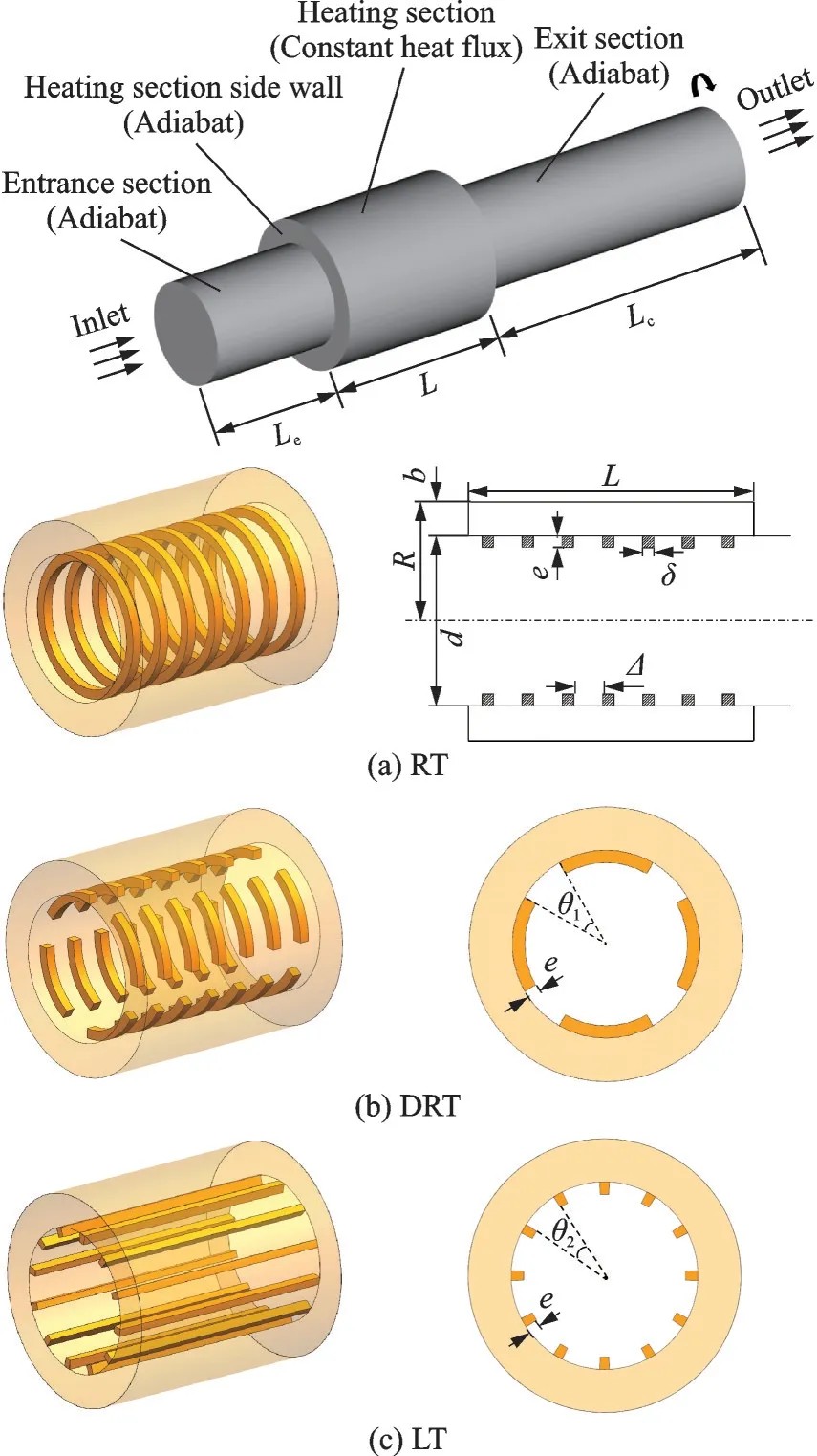
Fig.2 Schematic diagram of rib configurations inside rotating hollow rotor
2 Description of Computational Methodology
2.1 Numerical modeling
Considering the internal flow in a pipe that rotates about its axis with a rotating angular velocityω, the governing equations for momentum and energy transports are modified in the relative velocity or rotating reference frame, wherein the relative velocity is used[25]
wherevris the relative velocity andτthe viscous stress.The momentum equation contains two additional terms, the Coriolis acceleration term (2ω×vr) and the centripetal acceleration term (ω×ω×r).Since local temperature changes and local pressure changes will cause density changes, resulting in buoyancy, the centrifugal buoyancy termF=ρ0βΔT(ω×ω×r) is introduced, andρ0is the reference density.The energy equation uses the relative total enthalpyHrand (τ·vr) is the energy transport due to viscous dissipation.ρandkare the density and thermal conductivity of air, respectively.
The corresponding boundary conditions are summarized as the follows:
(1) For the rotating pipe, a rotating angular velocityωis given, and the rotational Reynolds numberReωis defined as
whereμisthe dynamic viscosity of air.
(2) The inlet of axial throughflow is set as velocity inlet by giving the mass flowrateQm.The inlet temperature is set as 300 K.The axial throughflow inlet Reynolds numberRexis defined as
whereUinis the bulk-averaged velocity at tube inlet.
(3) The outlet is set as a pressure out, by settingpout=101 325 Pa.
(4) On the heating section, a constant heat fluxqis imposed.Whereas for the other solid surface, the adiabatic thermal condition is adopted.On the solid surface, no slip velocity is adopted.
In the current study, the mass flowrate of axial throughflow is set asQm=5 kg/h and the corresponding axial-throughflow inlet Reynolds numberRexis about 6 400.The rotating angular velocityωis varied between 0 r/min and 1×10⁵r/min, and the corresponding rotational Reynolds numberReωis varied from 0 to 3.77×10⁴.The heat flow of the rotor surface under different conditions is obtained by numerical calculation, and the average value is selected as the thermal boundary condition of this study.The heat flux imposing on the heating section is set asq=6 950 W/m2.During the fluid-solid coupling, the thermal conductivity of solid wall is set as
16.3 W/(m·K).
2.2 Computational methodology
The current numerical simulations are performed by using the commercial CFD solver ANSYS Fluent, wherein 3-D steady-state flow and temperature fields are solved.The working fluid is treated as an ideal gas on account of the compressible effect.Its thermal physical parameters are set as the ideal-gas based density.Kinetic-theory based specific heat and thermal conductivity.Sutherland law based viscosity.The second order upwind scheme is used for the spatial discretization of convective terms in the conservation equations.In the momentum equation, the PRESTO scheme is used for the discretization of pressure gradient term.With regard to the pressure-velocity coupling, the SIMPLE algorithm is adopted.The convergence is regarded to be achieved when all normalized residuals of concerned variables fell below 1.0×10⁻⁵.
Computational grids are generated by using ICEM software.The structured meshes are adopted in the whole computational domain.The first layer of computational meshes is located at near-wall zone with a space of 0.02 mm normally to the solid surface, andy+is 1, which meets the requirement of the enhanced wall function.Then the computational meshes are stretched away from the viscous wall using a stretching ratio of 1.1.To make sure the computational result is independence of the computational mesh, a grid independency test is carried out in advance.As demonstrated in Fig.3 (l/Dis the ratio of the length between the position on the heating section and the inlet to the diameter of the channel), when the grid number is beyond 2.9 million the computed circumference-averaged temperature distribution at the heating section is not sensitive to the grid number.Thus a final grid number is selected around 3 million.

Fig.3 Grid independence test
To justify the current computational methodology on modelling the flow field inside a rotating pipe, an example validation is performed in advance against the experimental test by Imao et al[12].Beside, the selection of reasonable two-equation turbulence model for the the turbulence closure is also made from the comparison.As demonstrated in Fig.4 (r/Ris the ratio of the radial position to the radius of the pipe), it is confirmed that all the selected two-equation turbulence models provide nearly the same prediction on the azimuthal velocity profile in radial direction, andW/ωris the ratio of the tangential velocity to the tangential velocity of the rotating pipe.Regarding the axial velocity profile in radial direction (U/Uinis the ratio of the axial velocity to the inlet velocity), it is found both RNGk-εturbulence model and Realizablek-εturbulence model could provide more correct prediction with respect to the experimental data.Referring previous researches relating to the numerical simulations of rotating flow[26-28], RNGk-εturbulence model is selected in current study.

Fig.4 Validation of turbulence models
3 Results and Discussion
3.1 Flow fields
In a rotating tube, the Coriolis force and centrifugal force caused by the rotation make the internal flow complicated when compared to the stationary situation.Fig.5 shows the local three-dimensional flow trajectories inside a smooth pipe(SP), colored by the temperature value.Generally, the flow field inside a rotating pipe suffers to dual roles of forced axial through flow and rotation-induced azimuthal flow.When the pipe rotates at a small rotating speed or rotational Reynolds number (such asReω=807), the azimuthal flow induced by pipe rotation makes the flow trajectory deflect slightly in the circumferential direction.At a big radial location where the local flow zone is close to the rotating wall, the flow trajectory deflection behaves more strongly because of radially growing centrifugal forces.In a total, the forced axial through flow is dominant in the situations of small rotating speeds.However, when the pipe rotates at a high rotating speed or rotational Reynolds number (such asReω=3.77×10⁴), the rotation-induced azimuthal flow is dominate on the internal flow field, making the flow trajectories take on a significant spiral flow feature,because of the superposing of axial through flow.When compared to the small rotational Reynolds number situation, the axial flow in the entrance section is concentrated to the central zone of the rotating pipe, indicating that the inlet flow of forced axial flow is locally blocked at the big radial location because of the rotation effect.Along the axial direction, the spiral flow trajectory extends outward in the radial direction gradually.Meanwhile, the fluid temperature in the near-wall zone of heating section is obviously higher than that in the small rotational Reynolds number situation, indicating that the convective heat transfer capacity is raised in the high rotational Reynolds number situation.
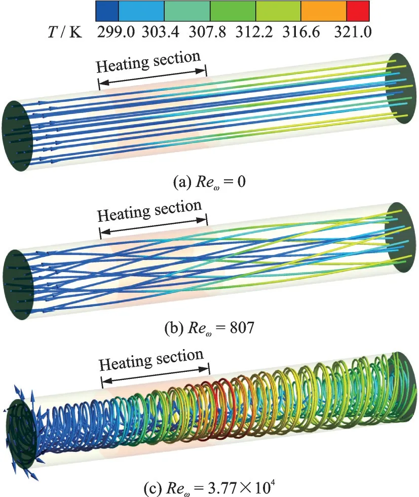
Fig.5 Flow trajectories inside smooth pipe under stationary and rotating states
The rotation-induced azimuthal flow changes the static pressure distribution inside the pipe, as demonstrated in Fig.6.In the stationary situation,the internal flow along the flow direction is classically characterized by a relatively regular favourablepressure flow.With the increase of rotational Reynolds number, the static pressure in the near-wall zone is increased because the near-wall fluid suffers the stronger Coriolis force and centrifugal force.Meanwhile, the static pressure in the central zone of a rotating pipe is decreased on the otherwise.Especially, when the pipe rotates at a high rotational Reynolds number, a low-pressure zone occurs inside the rotating pipe, occupying nearly entire axial length.This formation of low-pressure zone not only affects the internal flow inside the pipe, but also affects the outflow at the outlet.Due to this lowpressure zone, the external ambient air would even be suctioned into the central zone of a rotating pipe from the outlet plane.

Fig.6 Pressure contours in side smooth pipe
As the internal flow field is dramatically changed by the rotational effect, the roles of ribroughened turbulators on the flow disturbance are conjectured to be changed in accordance with the rotational Reynolds number.The local streamlines in the vicinity of rib-roughened zone are displayed in Figs.7—9, corresponding to different rib configurations.In these figures, the streamlines are colored by the dimensionless velocity, or the velocity ratio of locally absolute velocity to the bulk-averaged velocity at tube inlet (Uin).
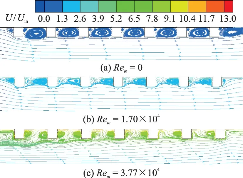
Fig.7 Local streamlines inside RT

Fig.8 Local streamlines inside DRT
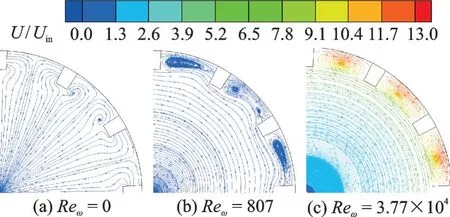
Fig.9 Local streamlines inside LT
For the RT, a large-scale vortex structure is formed in the interval region after the axial through flow passes through the ribs in the stationary situation, as displayed in Fig.7(a).The transverse rib plays a promising flow disturbance role on the internal flow.As the rotational Reynolds number increases, the flow velocity in the high radial location is increased.The rotation-induced azimuthal flow becomes dominate gradually, making the size of vortex structure between ribs reduction radially, as displayed in Fig.7(b).In particular, under a high rotational Reynolds number, the rotation-induced azimuthal flow is dominant significantly, the absolute velocity near the wall surface is obviously greater than the bulk-averaged velocity of the axial throughflow, the flow disturbance role of ring-type rib on the helicoidal flow is apparently weakened with respective to the stationary situation, as demonstrated in Fig.7(c).Also, it is conjectured that the heat transfer enhancement role of ring-type rib layout would be reduced in the high rotational Reynolds number situation.
For the DRT, the flow disturbance role on the internal flow is nearly the same as the ring-type rib layout.Because there is a gap between discrete ring ribs in the circumferential direction, the local flow disturbance also appears in the vicinity of this gap in the stationary situation, as displayed in Fig.8(a).In the rotating situations, the discrete ring ribs could introduce a flow disturbance role to the rotation-induced azimuthal flow, as displayed in Fig.8(b) and Fig.8(c).
For the LT, the flow disturbance role of longitudinal rib on the axial flow is very weak in the stationary situation, as displayed in Fig.9(a).However, in the rotating situations, the longitudinal rib layout shows its superiority on disturbing the local flow in the rib-roughened region, to the rotation-induced azimuthal flow.Under a small rotational Reynolds number, the rotation-induced azimuthal velocity is small, such that the vortex structure is composed by the low-velocity fluid, as displayed in Fig.9(b).Under a high rotational Reynolds number, the rotationinduced azimuthal velocity is strong, such that the vortex structure is composed by the high-velocity fluid, as displayed in Fig.9(c).
From the above-mentioned analysis, it is confirmed that the rotation has a significant effect on the internal flow field, altering the flow disturbance roles of rib layout on the internal flow.As a consequence, the heat transfer enhancement role of rib layout would be changed in accordance with the rotational Reynolds number.
3.2 Flow and heat transfer performances
Fig.10 displays the temperature contours in the solid region at the middle plane of heating section,in the stationary situation.It is seen that temperature of heating section could be effectively reduced by utilizing the inner rib-roughened configurations,when compared to the SP at the same axial throughflow mass flow rate.By comparing three different rib configurations, the ring-type ribs, either in continuous (RT) or discrete (DRT), provide better cooling roles than the LT.With respect to the SP,the RT could reduce the peak temperature of heating section about 64K.Only about 34 K reduction is achieved by the LT.
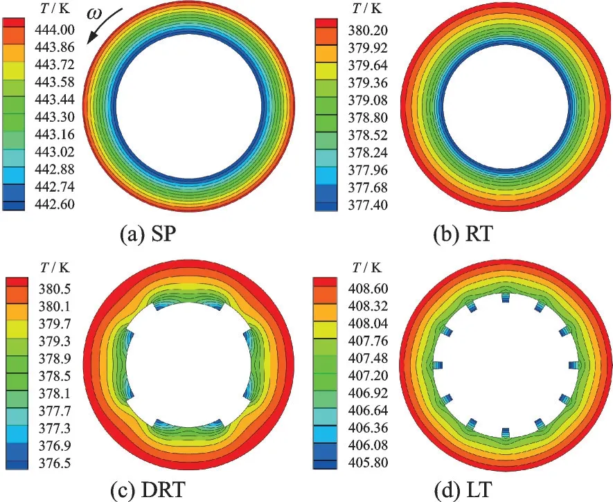
Fig.10 Temperature contours on middle-axial plane of heating section under Reω=0
Fig.11 displays the temperature contours in the solid region at the middle plane of heating section,in the rotating situation atReω=3.77×10⁴.When compared to the stationary situation, the peak temperature is reduced obviously because the strong helicoidal flow enhances the convective heat transfer capacity.Taking the SP as an example, the peak temperature is reduced about 70 K in the high rotational Reynolds number situation relative to the stationary situation.With respect to the SP, the rotation effect on internal convective heat transfer of ribroughened tube is weakened.In particular, for the RT, the peak temperature underReω=3.77×10⁴has only about 16 K reduction in relative to the stationary situation.When compared to the SP at the same rotational Reynolds number, only about 9 K reduction in the peak temperature is achieved by the RT.Apparently, in the high rotational Reynolds number situation, the LT presents the best convective heat transfer enhancement owing to its strongest flow disturbance role to the rotation-induced azimuthal flow.

Fig.11 Temperature contours on middle-axial plane of heating section under Reω=3.77×10⁴
Fig.12 displays the peak temperature variations of heating section with the rotational Reynolds number.It is seen that the peak temperature is decreased with the increase of rotational Reynolds number generally.For the SP and LT, the peak temperature is reduced rapidly with the rotational Reynolds number whenReωis increased from 0 to 1×10⁴.While for the RT and DRT, the peak temperature is not sensitive to the rotational Reynolds number in a wide range.It is noteworthy that when the rotational Reynolds number is less than 2 400, the RT and DRT provide a better heat transfer enhancement than the LT.Whereas under high rotational Reynolds numbers, the LT is more pronounced for reducing the peak temperature of heating section.
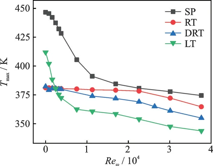
Fig.12 Effects of rotational Reynolds number and rib type on peak temperature of rotor
The rib-roughened configuration inside a rotating tube enhances the convective heat transfer but also leads to a serious pressure loss.In order to assess the comprehensive effects of ribbed configuration, a comprehensive performance factor is introduced,which is defined as
whereNuis the area-averaged Nusselt number andfthe friction factor.The subscript “0” represents the baseline case for the comparison.Here the corresponding smooth tube under the same rotational Reynolds number is selected as baseline case.
The area-averaged Nusselt number over the heating section and the friction factor across the entire pipe are defined as
wherehis the area-averaged convective heat transfer coefficient over the inner surface of heating section;λandρare the thermal conductivity and the density of the air, respectively; (pin-pout) is the pressure drop of the internal flow across the lengthLof the pipe.
For the SP, the effects of rotation on the areaaveraged Nusselt numberNu0and friction factorf0are displayed in Fig.13.In general, both the convective heat transfer and the flow loss are increased monotonically with the rotational Reynolds number.However, the influencing tendency of rotational Reynolds number onNu0is somewhat different from that onf0.Regarding the convective heat transfer capacity, as seen in Fig.13(a),Nu0is increased rapidly along the rotational Reynolds number in a nearly linear mode whenReωis increased from 0 to 1×10⁴.WhenReωis beyond 1×10⁴, the increase rate ofNu0alongReωbecomes degraded.Whereas regarding the friction factor, as seen in Fig.13(b),f0is weakly increased along the rotational Reynolds number whenReωis less than 0 to 1×10⁴.WhenReωis beyond 2×10⁴, the friction factor is increased sharply with the rotational Reynolds number.Identified from Fig.13, under a high rotational Reynolds number ofReω=3.77×10⁴, the Nusselt number and friction factor are about two times and five times of the corresponding values in the stationary situation, respectively.

Fig.13 Effects of rotational Reynolds number on Nu0 and f0 for smooth pipe
Fig.14 shows the variations of average Nusselt numberNuand friction factorfwith the rotational Reynolds number, for the rib-roughened pipes.It is confirmed that the effects of rotation on the Nusselt number and friction factor of rib-roughened pipe are similar to the smooth pipe.However, the variation tendencies of convective heat transfer and friction with rotational Reynolds number are somewhat distinct for different rib-roughened configurations, because of different flow disturbance roles of rib layout on the internal flow.Taking the SP as a baseline case for comparison, Fig.15 presents directly the variation patterns of convective heat transfer enhancement ratio (——-Nu/Nu0), friction factor ratio(f/f0) and comprehensive performance factor(PEC) along with the the rotational Reynolds number, for three different rib-roughened configurations.With respect to the baseline SP, all the ribroughened pipes show their heat transfer enhancement role but also increase the flow loss.Their influencing roles are tightly dependent on the rotational Reynolds number, showing a non-monotonic variation.

Fig.14 Effects of rotational Reynolds number on Nu and f for rib-roughened pipes

Fig.15 Comparison between different rib configurations in view of comprehensive factor
Under small rotational Reynolds numbers(such asReω<2 400), the RT and DRT provide bigger convective heat transfer enhancement ratio but also bigger friction factor ratio than the LT.In the viewing of the comprehensive performance factor that considers both heat transfer enhancement and flow loss together, the DRT is identified to be the best among the current three rib configurations.
Under high rotational Reynolds numbers(such asReω>2×10⁴), the LT provide bigger convective heat transfer enhancement ratio but also bigger friction factor ratio than the RT.It is noteworthy the RT show no advantage over SP, and even lead to a reduction in the comprehensive performance factor when compared to the smooth pipe.Therefore, for the high-speed rotating tube, the LT is suggested to be a more promising rib configuration as applied to the heat transfer enhancement.
4 Conclusions
A numerical study is conducted to illustrate the flow and heat transfer characteristics inside a rotating rib-roughened pipe with an axial throughflow,under a fixed axial-throughflow Reynolds numberRexof 6 400 and a series of rotational Reynolds numberReωranging from 0 to 3.77×10⁴.Three rib configurations, including RT, DRT and LT, are taken into consideration.From current study, the main conclusions are summarized as the follows:
(1) The flow field inside a rotating pipe is of high complexity, due to the dual influencing aspects from the axial through flow and the rotation-induced azimuthal flow.The dominant flow feature and subsequently the flow of rib-roughened flow disturbance role is tightly dependent on the competition between axial through flow and rotation-induced azimuthal flow.
(2) Under small rotational Reynolds numbers,the axial through flow is dominant such that the RT plays a significant flow disturbance role and subsequently the strong heat transfer enhancement.Whereas under high rotational Reynolds numbers,the rotation-induced azimuthal flow is dominant such that the LT is superior to the RT on the flow disturbance and subsequently heat transfer enhancement.
(3) Evaluated on the comprehensive performance factor that considers both heat transfer enhancement and flow loss together, the DRT is identified to be the best among the current three rib configurations under small rotational Reynolds numbers.However, under high rotational Reynolds numbers, the LT layout is a promising rib configuration as applied to the heat transfer enhancement.
杂志排行
Transactions of Nanjing University of Aeronautics and Astronautics的其它文章
- Study on Microhardness and Texture of AlFeMn Alloy Sheets During Cold Rolling
- Traffic Flow Prediction Model Based on Multivariate Time Series and Pattern Mining in Terminal Area
- Method for Aircraft Sheet Metal Part Recognition Based on Cascading Virtual-Real Fusion
- Effect of Broaching Machining Parameters on Low Cycle Fatigue Life of Ni-Based Powder Metallurgy Superalloy at 650 ℃
- Real-Time Optimal Control for Variable-Specific-Impulse Low-Thrust Rendezvous via Deep Neural Networks
- A Monte Carlo Lagrangian Droplet Solver with Backpropagation Neural Network for Aircraft Icing Simulation
