SOLPS-ITER drift modeling of neon impurity seeded plasmas in EAST with favorable and unfavorable toroidal magnetic field direction
2023-11-19FuqiongWANG王福琼YunfengLIANG梁云峰YingfengXU徐颖峰XuejunZHA查学军FangchuanZHONG钟方川SongtaoMAO毛松涛YanminDUAN段艳敏andLiqunHU胡立群
Fuqiong WANG (王福琼) ,Yunfeng LIANG (梁云峰) ,Yingfeng XU (徐颖峰),* ,Xuejun ZHA (查学军) ,Fangchuan ZHONG (钟方川) ,Songtao MAO (毛松涛) ,Yanmin DUAN (段艳敏) and Liqun HU (胡立群)
1 Department of Applied Physics,College of Science,Donghua University,Shanghai 201620,People’s Republic of China
2 Member of Magnetic Confinement Fusion Research Center,Ministry of Education,Shanghai 201620,People’s Republic of China
3 Forschungszentrum Jülich GmbH,Institut für Energie-und Klimaforschung Plasmaphysik,Jülich 52425,Germany
4 Institute of Plasma Physics,Chinese Academy of Sciences,Hefei 230031,People’s Republic of China
Abstract To better understand divertor detachment and asymmetry in the Experimental Advanced Superconducting Tokamak (EAST), drift modeling via the comprehensive edge plasma code SOLPS-ITER of neon impurity seeded plasmas in favorable/unfavorable toroidal magnetic field(BT)has been performed.Firstly,electrostatic potential/field(ϕ/E)distribution has been analyzed,to make sure thatϕ and E are correctly described and to better understand drift-driven processes.After that,drift effects on divertor detachment and asymmetry have been focused on.In accordance with the corresponding experimental observations,simulation results demonstrate that in favorable BT the onset of detachment is highly asymmetric between the inner and outer divertors;and reversing BT can significantly decrease the magnitude of in-out asymmetry in the onset of detachment,physics reasons for which have been explored.It is found that,apart from the well-known E×B drift particle flow from one divertor to the other through the private flux region,scrape-off layer(SOL)heat flow,which is much more asymmetrically distributed between the high field side and low field side for favorable BT than that for unfavorable BT,is also a critical parameter affecting divertor detachment and asymmetry.During detachment,upstream pressure(Pu)reduction occurs and tends to be more dramatical in the colder side than that in the hotter side.The convective SOL heat flow,emerging due to in-out asymmetry in Pu reduction,is found to be critical for understanding divertor detachment and asymmetry observed in EAST.To better understand the calculated drastic power radiation in the core and upstream SOL,drift effects on divertor leakage/retention of neon in EAST with both BT directions have been addressed for the first time,by analyzing profile of poloidal neon velocity and that of neon ionization source from atoms.This work can be a reference for future numeric simulations performed more closely related to experimental regimes.
Keywords: drifts,electric potential/field,asymmetry,divertor detachment,impurity transport
1.Introduction
In the high-power operation of modern tokamaks,e.g.EAST [1] and ITER [2] etc,a large amount of power crossing the separatrix from core plasma to the scrape-off layer (SOL) [3] must be dissipated before reaching the divertor plates to avoid excessive erosion of target material.Seeding impurities into the divertor region for increasing radiative power loss is a promising approach to realize semi-detached/detached operation regimes [4] needed for heat load [5] alleviation in the long-pulse high-power operation of tokamaks.Particularly,in future fusion devices with full-metal walls (e.g.ITER),extrinsically seeded impurities are indispensable for heat flux control at the divertor plates.How to reduce divertor heat load most effectively with a minimal contamination to core plasma remains still a great challenge for current and next-generation tokamaks.Hence,it is essential to have a profound understanding of the impurity seeded plasmas in diverted tokamaks,including the understanding of divertor detachment,asymmetry and divertor retention of impurities.
E×Band diamagnetic drifts are found to play an important part in tokamak edge.Particularly,effects ofE×Bdrift on impurity transport[6]as well as on divertor detachment [7] and asymmetry [8] are considered to be remarkable.Typical drift-flow patterns for the both directions of toroidal magnetic field (BT) have been shown in figure 1.From figure 1,in plasmas with favorable BTdirection (i.e.with the ionB×∇Bdrift pointing downwards for plasmas with lower-single null (LSN) configuration),bothEr×BandEθ×Bdrifts tend to drive plasma ions from the outer divertor region to the inner one through the private flux region(PFR),making plasma in the inner divertor region to be more dense and colder than that in the outer one.Usually,inverting of BTfrom the favorable direction to the unfavorable one leads to the reduction or even the reversing of in-out asymmetry [3].However,the actual drift-flow patterns in tokamak edge have been demonstrated to be much more complicated than that shown in figure 1.In DIII-D,it is found that,for favorable BT,the onset of divertor detachment exhibits a bifurcated feature due to the non-linear dependence ofE×Bdrift on the electron temperature (Te) and the electric potential (ϕ)[7].Recent investigations in TCV revealed that,in detached plasmas with unfavorable BT,an electric potential well [9]forms near the X-point,under the circumstance that Pfirsch-Schlüter currents dominate the parallel current [3],leading to the deviation of divertorE×Bdrift flow from the classical pattern shown in figure 1.This deserves close attention for advanced tokamak scenarios,e.g.reverse triangularity plasmas,I-mode operation etc.In EAST,divertor detachment and asymmetry have been experimentally demonstrated to be significantly influenced by magnetic field direction [10],physics reason for which lies in the influences ofE×Bdrift.However,to quantitatively describe the drift-driven processes in EAST,detailed modeling and analysis are still required.
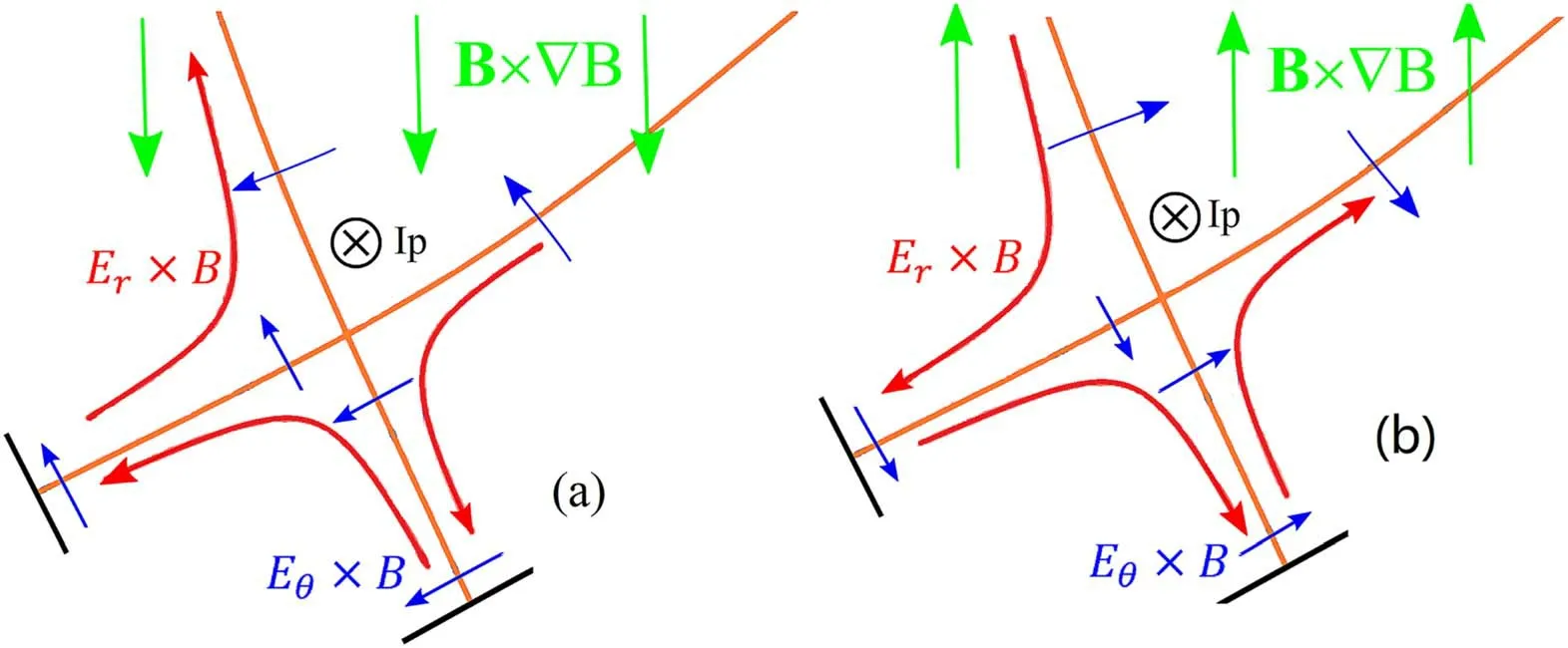
Figure 1. Typical drift flow patterns of plasma ion in lower single null (LSN) configuration for favorable (a) and unfavorable (b) toroidal magnetic field direction.
Generally,various impurity species,such as Kr [11],nitrogen (N),neon (Ne) and argon (Ar) [12] can be seeded into divertor plasmas for power exhausting.However,so far,no conclusion on the best candidate impurity for future fusion reactors has yet been drawn.Presently,because of the lithium(Li) coating for daily wall conditioning and the strong chemical activity of N2and Li,seeding N2into EAST is not allowed.Besides,recent experiments in EAST revealed that neon is more compatible with the core plasma than argon in detached regimes [13].Hence,this paper will focus on divertor detachment and asymmetry affected by drifts and neon seeding level in EAST with favorable/unfavorable BT,by performing numerical simulations with the comprehensive SOLPS-ITER code [14,15].Besides,first study on neon impurity transport in divertor/SOL region of EAST with favorable/unfavorable BTwill also be addressed in this paper.A detailed reproduction of any particular experimental discharge is not attempted,but the simulations are aimed to provide a further understanding of present experimental observations.This paper is organized as follows.Section 2 introduces details about the simulation setups.Then,section 3 describes the simulation results and discussions.Finally,section 4 gives the conclusions.
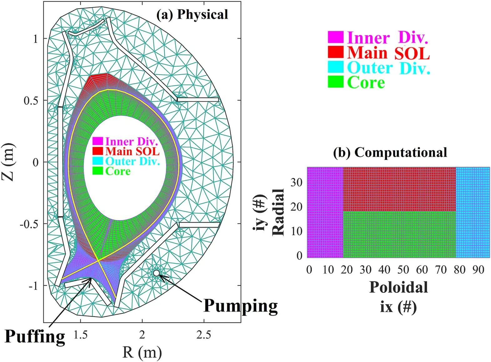
Figure 2.(a)Meshes for B2.5(i.e.the quasi-orthogonal meshes poloidally aligned along the flux surfaces)and for EIRENE(triangular).The in-vessel structures as well as the pumping and puffing locations are also shown,(b) the computational meshes for B2.5.
2.Modeling setup
As mentioned above,the simulation work has been fulfilled by SOLPS-ITER [14,15],coupling the three-dimensional kinetic neutral transport code EIRENE [16] and the twodimensional multi-fluid plasma solver B2.5 [17].The effects of drifts and currents are self-consistently considered.Neon impurity has been injected into the divertor region from dome,as shown in figure 2(a).Behaviors of the electron,deuterium ion (D+) and neon ions (Ne1+,Ne2+,…,Ne10+)are treated by the multi-fluid B2.5 code,solving the Braginsky set of equations [18].Transport of neutrals (i.e.D2,D,Ne) as well as the sources/sinks of energy,particle and energy due to the molecular/atomic processes (e.g.ionization,recombination,charge-exchange,etc) is tackled by EIRENE based on the background plasma conditions provided by B2.5.Since the molecular ionhas a very short life-span and can be easily recombined into a molecule (i.e.D2),it is also treated by EIRENE.
SOLPS-ITER calculations are performed based on the grid shown in figure 2,which has been generated from a typical magnetic equilibrium(with the elongationκ=1.674,upper/lower triangularityδu/δl=0.288/0.560,q95=5.0)in EAST with LSN configuration.Calculation grid shown in figure 2(a)consists of the quasi-orthogonal(96 poloidal×36 radial) meshes,poloidally aligned along the flux surface,for B2.5 and the triangular meshes for EIRENE.At the outboard midplane (OMP),B2.5 meshes radially extend from-10.0 cm (outer core) to~3.0 cm (SOL).Besides,to facilitate the analysis,the computational meshes (figure 2(b))together with definitions of the calculation regions(including the‘core’,the main SOL and both divertors)are also depicted in figure 2.Based on typical plasma conditions in EAST,the plasma current (Ip) and toroidal magnetic field (BT) are set to be Ip=400 kA and BT=1.8 T,respectively.Basically,plasma conditions at the boundaries of divertor targets,PFR,outer SOL and the core-edge interface (CEI) require to be given for SOLPS-ITER calculations.In our simulations,plasma boundary conditions are set as follows:(1)at the CEI,density of D+is fixed to nu=3.0×10¹⁹m-3,the particle fluxes of neon (Ne1+,Ne2+,…,Ne10+) are set to be zero.Since the neutral deuterium (D0) and neutral neon (Ne0)species are treated by EIRENE,boundary conditions for them on the B2.5 side are unimportant.On the EIRENE side,the CEI is assumed to absorb all the neutrals impinging from the outer side.Besides,the electron and ion temperatures are specified to be Te=Ti=500 eV,thus heat flux into the calculation region through CEI is~1 MW;(2) boundary condition at the last SOL flux surface is assumed to be leakage type,similar to that shown in [19];(3) the standard sheath boundary condition is used at the divertor targets;the plasma flow is assumed to be at least sonic at entrance of sheath,i.e..Here,V‖,Bθ/B and n denote the parallel flow velocity,magnetic field (poloidal/total) and plasma density,respectively.Since the drifts are included in the calculations,boundary conditions at the targets are revised as:,where Vprepresents the poloidal projection of total drift velocities [8].At the surfaces of plasma facing components,the recycling coefficient(Rcoef)is specified as follows.Rcoeffor divertor plates and that for the main chamber are set to be 1.0.For the pumping hole with a surface area of 2.087 m2(figure 2(a)),Rcoefis specified to be 0.9152,so that the pumping speed is about 76 m3·s-1which is close to typical pumping capability of the cryopump in EAST [20,21].
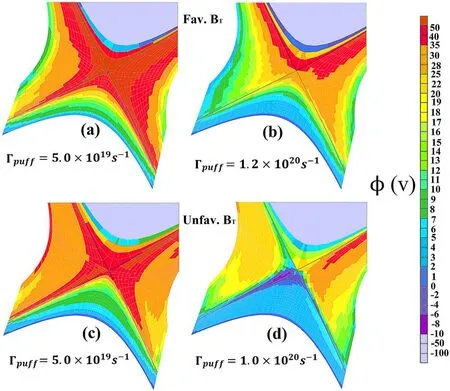
Figure 3.SOLPS-ITER calculated distributions of electric potential(ϕ)in the divertor region for favorable((a)and(b))and unfavorable BT((c) and (d)) at different neon seeding rates.
3.Simulations results
3.1.Electrostatic potential and field
E×Bdrift has been considered to greatly affect divertor detachment and asymmetry [22,23],and significantly influence divertor retention/leakage of impurities [6].To profoundly understand the drift flow patterns in EAST with both BTdirections,distribution of electric potential (ϕ) in the calculation region should be correctly described.Recent investigations [7,9,24] demonstrated that electric potential distribution is tightly connected to divertor operation regimes(e.g.high-recycling,detachment etc) and to magnetic-field direction.According to[9,24],in attached regimes with high divertor plasma temperature (Te) (i.e.Te>2 eV),the Spitzer resistivityis so small that parallel current (j‖)has a little contribution to parallel electric field (E‖);while in detached plasmas with low divertor Te,the Spitzer resistivity is significant so thatj‖contributes much toE‖.Besides,in detached plasmas with favorable/unfavorable BT,the dominant contribution ofj‖toE‖will lead to the formation of electric potential hill/well near the X-point [7,9],under the circumstance that the local charge balance in divertor is contributed predominantly byj‖and diamagnetic current.The X-point potential well and hill may greatly affect the divertor plasma performances.Hence,main characteristics of the electric potential (ϕ) distribution calculated in the simulations are analyzed and shown in the following part.
Typical distributions of the electrostatic potential (ϕ) in favorable and unfavorable BTat different neon seeding rates are shown in figure 3.From figure 3,similar to results from SOLPS-ITER drift modeling of edge plasmas in TCV [9],divertor electric potential (ϕ) profile for favorable BTfollows the classical picture [3],i.e.with the radial electric field (Er)directed away from the separatrix and the parallel electric field (E‖=-∇‖ϕ) towards the target plates (figures 3(a) and(b));while for unfavorable BT,the so-called X-point potential well [9],which reverses the electric field near the X-point,emerges in detached regimes at high neon seeding rates.Hence,based on the above-mentioned theories and the distribution of electric potential shown in figure 3,we can infer thatj‖anddominates charge balance in the divertor region of EAST,which is the same case as those on DIII-D[7,25],AUG[24],COMPASS[26].This can be further demonstrated by data in table 1,which illustrates the calculated contributions to the divergence of electric current in both divertors for favorable and unfavorable BTat relatively high neon puffing rate.The infulence of X-point potential well on plasma and impurity transport in EAST will be described in section 3.3.
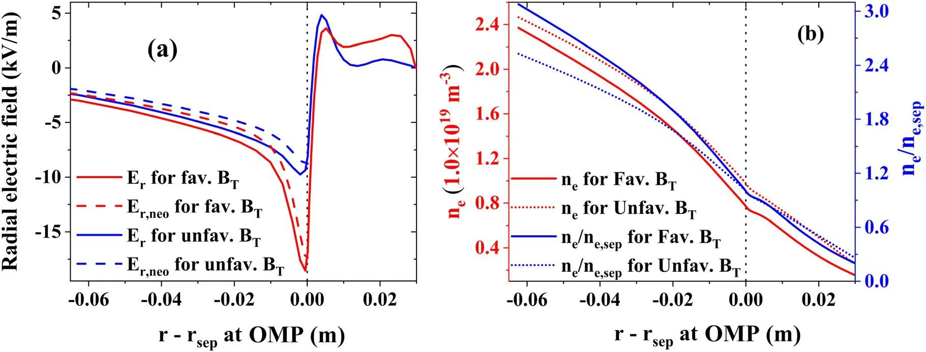
Figure 4. Radial profiles of electric-field (a) and ne (b) at the outboard midplane (OMP) in favorable/unfavorable BT at Γpuff=5.0×10¹⁹ s-1.For a better comparison of ne radial gradient,OMP ne values for favorable BT together with those for unfavorable BT are normalized to the corresponding separatrix plasma density ne,sep and are also shown in figure 4(b) (in blue).
Table 1.SOLPS-ITER calculated contributions to the divergence of electric current in both divertors for =1.2 ×10 20s-1 and =1.0 ×10 20s-1.The charge balance is dominated by parallel and diamagnetic currents.
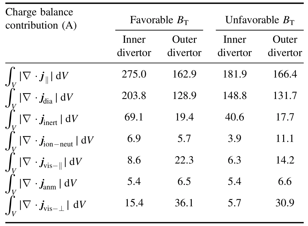
Table 1.SOLPS-ITER calculated contributions to the divergence of electric current in both divertors for =1.2 ×10 20s-1 and =1.0 ×10 20s-1.The charge balance is dominated by parallel and diamagnetic currents.
Similar to results from simulations with SOLPS5.2[17,27]and SOLPS-ITER[28]for present tokamaks[17]and for ITER[27,28],radial electric field(Er)in the outer core is found to be close to its neoclassical value,as shown in figure 4.According to equation (42) in [17],neoclassical value of Erdepends on the parallel velocity(V‖),radial density(∂/n∂r) and temperature (∂/T∂r) gradients.In our simulations,as BTdirection reverses,the radial temperature gradient(∂T/∂r) (see figure 3 in [19]) and the magnitude ofV‖in the outer core changes slightly.Thus,contribution of ∂/T∂rand that ofV‖to neoclassical value of Erare insensitive to BTdirection.Consequently,compared with the favorable BTcases,the unfavorable BTcases tend to have smaller Erin the outer core (figure 4(a)) because of the smaller neoclassical contribution related to the radial gradient of plasma density(figure 4(b)).That is,radial density profiles in favorable BTtend to be steeper than those in unfavorable BT,in accordance with results from the previous experiments [29] and simulations [19] on EAST.Besides,for unfavorable BT,in the far SOL(of >1 cm radial distance to separatrix),Ervalue is very small (figure 4(a)),implying a small poloidal ion flux driven byEr×B,compared with that in the near SOL,details about which will be describe in section 3.3.
3.2.Drift effects on divertor detachment and asymmetry
Figure 5 depicts the calculated radial profiles of plasma density (ne) and temperature (Te) at the targets and outer midplane (OMP) for favorable/unfavorable BTat different neon puffing rates (Γpuff).From figure 5,we can see that,in favorable BT,there exists a remarkable in-out asymmetry in target neand Te,while in unfavorable BTthe divertor asymmetry is reversed and the magnitude of which has been suppressed to some degree,in common with results from previous investigations [30].To elucidate the effects of drifts and neon seeding on divertor detachment and asymmetry,peak values of Teand heat fluxes(qt)together with the strikepoint values of Teat both divertor plates are plotted versus the neon seeding rate for the favorable and unfavorable BT(figure 6).Basically,with Te≲5 eV [4,31],transition of divertor operation from the attached regime to detached one will be induced by the energy loss,momentum loss and particle loss(manifested as roll-over of target ion current due to the reduction of sources(ionization)and/or the increase of sinks (recombination) [31,32]) processes.Hence,Te≲5 eV is taken as the criterion for detachment judgment in this work.
From figures 5 and 6,Teand qtat both divertor plates decrease as Γpuffincreases,in both favorable and unfavorable BT.However,values of Teand qtin the colder divertor region tends to be more insensitive to the increase of Γpuffthan those in the hotter divertor region.In favorable BT,with Γpuffincreased from 0 to 1.2×10²⁰-s,1 peak value of Teat the inner/outer target plate has been decreased from 19.8/51.7 to 2.5/10.2 eV,and the strike-point value of Teat the inner/outer divertor plate has decreased from 12.1/35.3 to 2.1/4.4 eV.In unfavorable BT,with Γpuffincreased from 0 to 1.0×10²⁰-s,1 peak value of Teat the inner/outer target plate has been decreased from 46.9/15.8 to 5.8/4.2 eV,and the strike-point value of Teat the inner/outer divertor plate has been decreased from 34.1/11.9 to 2.9/3.2 eV.Hence,in unfavorable BT,the in-out asymmetry of divertor plasma conditions can be remarkably reduced,asΓpuffincreases.

Figure 5.SOLPS-ITER calculated radial profiles of ne and Te at the mid-plane and targets for favorable(solid lines)and unfavorable BT(dash lines) at different neon puffing rates.
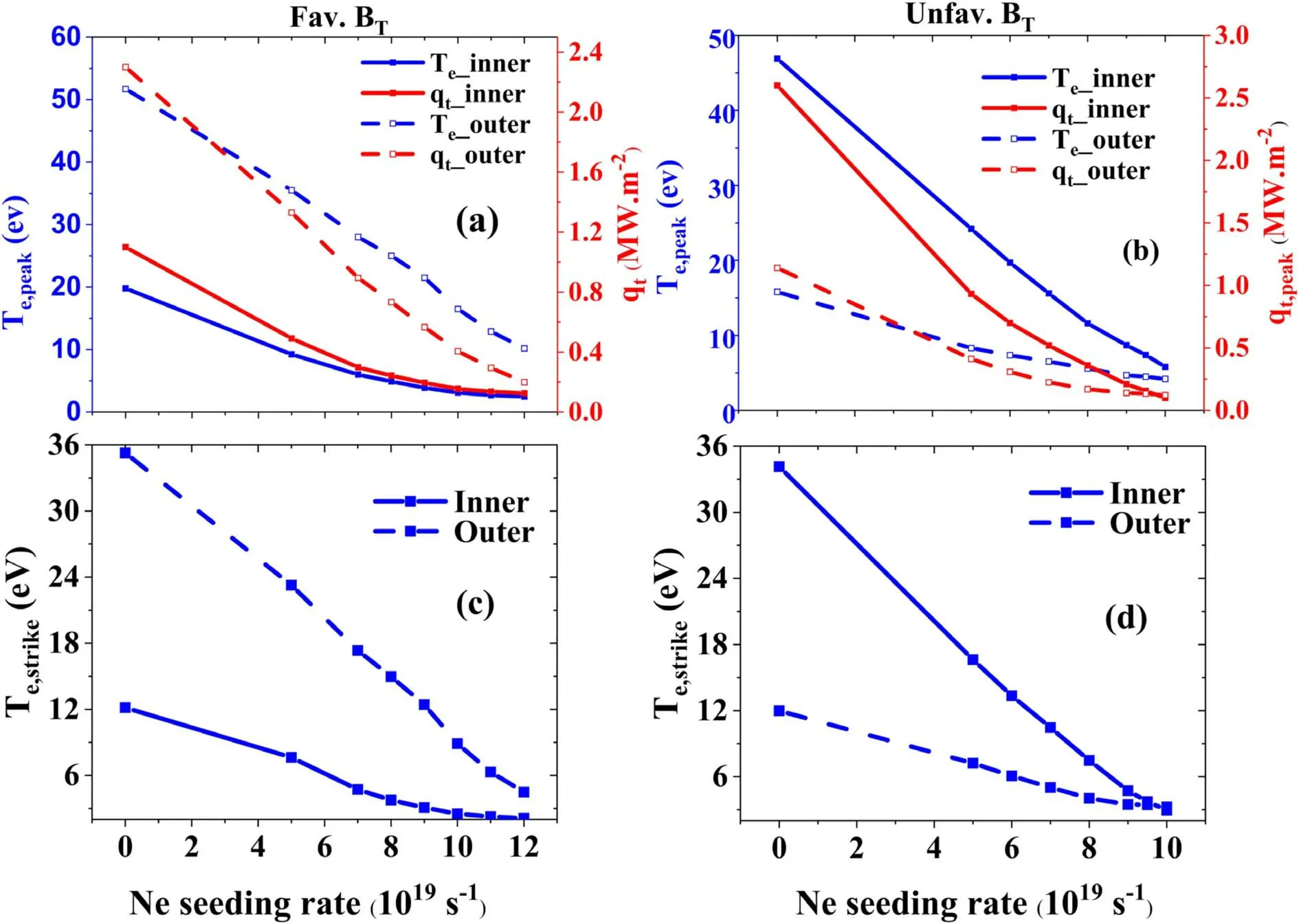
Figure 6.Peak values of plasma temperature(Te)and heat flux(qt)((a)and(b))together with the strike-point values of Te((c)and(d))at both divertor targets plotted versus the neon seeding rate for favorable ((a),(c)) and unfavorable ((b),(d)) BT.
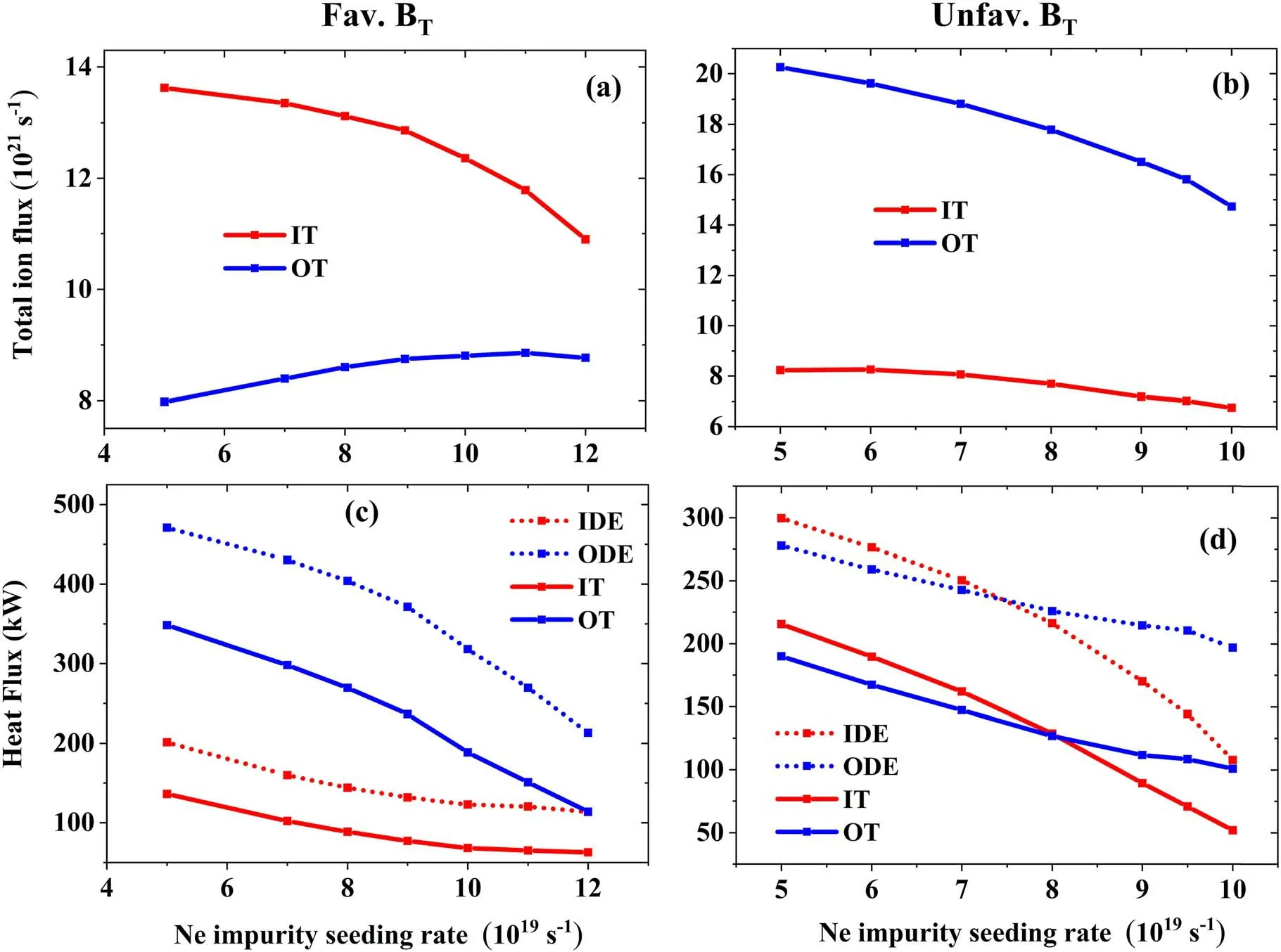
Figure 7.(a)and(b):total ion flux onto the inner(red)and outer(blue)target plates plotted against Γpuff for favorable-(a)and unfavorable-BT(b);(c) and (d): integrated heat flow into the inner divertor region via the inner divertor entrance (IDE) (red dotted-lines) and that into the outer divertor region via the outer divertor entrance(ODE)(blue dotted-lines)together with the integrated power heat load on the inner(red solid-lines) and outer (blue solid-lines) divertor target plates plotted against Γpuff for favorable-(c) and unfavorable-BT (d).
In favorable BT,with Γpuffincreased to be 7.0×10¹⁹-s1,the strike-point value of Teat the inner plate has been decreased to be<5 eV (~4.7 eV),so that the inner divertor plate becomes to be partially detached near the strike-point,and the degree of detachment from the inner plate increases as Γpuffincreases,as can be further demonstrated by the decrease(roll-over)of total ion flux(figure 7(a)).As for the plasmas in the outer divertor region,only when Γpuffhas been increased to be as high as 1.2×10²⁰-s1,the strike-point Tevalue can be decreased to be<5 eV (~4.5 eV),and the degree of detachment cannot be further increased by increasing Γpuff,due to the occurrence of radiation collapse.Hence,in accordance with the previous experimental observation [10],the onset of detachment is highly asymmetric between inner and outer divertors in EAST with favorable BT.
In unfavorable BT,with Γpuffincreased to be larger than 7.0×10¹⁹-s1,strike-point value of Teat the outer divertor plate can be decreased to be ≲5 eV,leading to the partial detachment of plasmas in the outer divertor region.AsΓpuffincreases further,Tevalues in the outer divertor region change slightly (figures 5(f) and 6(b)).In contrast,withΓpufffurther increased to be 9.0×10¹⁹-s,1 the inboard strike-point Tevalue decreases to be<5 eV (~4.7 eV),and Tein the inner divertor region decreases more dramatically than that in the outer divertor region.Hence,in-out asymmetry in neonseeding-level required for the onset of divertor detachment in unfavorable BTis much smaller than that in favorable BT.To elucidate physics reasons for divertor detachment and asymmetry observed in both the simulations and experiments for EAST,target flux of neon impurity,power flow into the divertor region and the distribution of radiative power loss have been analyzed.
In coronal equilibrium,power radiated by neon (Prad,z)can be expressed as [33]:
Here,nz,Lzand neare the neon density,radiation efficiency and electron density,respectively.The radiation efficiency Lzcan be inferred from atomic databases [34].However,it is notable that deviation from coronal equilibrium occurs in both experiments [11] and SOLPS-ITER simulations [35].Hence,equation (1) is just an approximation of radiative power loss in this work.Figure 8 gives the calculated radiative power loss(Prad)in different regions,including the core,SOL,inner and outer divertors.From figure 8,Pradin core and in SOL tend to be higher than that in the divertor region,for which there are two possible reasons.On one hand,according to previous simulations on radiation characteristics of impurity species in EAST[36],the maximum of radiation efficiency Lzfor neon tends to appear in the upstream around the separatrix.On the other hand,neon was experimentally observed to tend to leak towards the upstream in some tokamaks,such as ASDEX-upgrade [37] and DIII-D [38],leading to large core radiation.Drift effects on divertor leakage/retention of neon impurity in EAST with both BTdirections will be addressed in section 3.3.
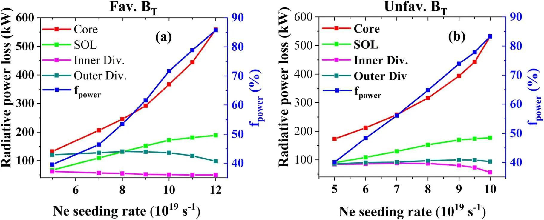
Figure 8.Total radiative power loss in different regions,including that in core,main SOL,inner divertor region and outer divertor region,plotted against Γpuff for favorable(a)and unfavorable(b)BT.Ratio of radiation power to power flux into the calculation region via the coreedge interface(PCEI ranging from~0.96 to~1.03 MW during neon seeding rate scan),i.e.fpower,has also been plotted(in blue)versus Γpuff for favorable (a) and unfavorable (b) BT.
As expected,power flow into both divertors can be decreased via increasing Γpuff(figures 7(c)and(d)),due to the increase of Prad,zin core and main SOL (i.e.SOL excluding divertor region)(figure 8).Although,the increase of Γpuffwill lead to the increase of divertor neon density nz,Prad,zin the divertor region cannot be increased effectively(figure 8),due to the strong temperature dependence of the radiation efficiency Lz[35].Hence,in our simulations,as Γpuffincreases,decrease of power heat load on divertor plates and the transition of the divertor operation regime from the attached to detached one are mainly caused by the decrease of power flow into the divertor region.
In favorable BTcases,total power flow from the upstream to the outer divertor region (POD) via the outer divertor entrance (ODE) is found to be more than twice as much as that to the inner divertor region (PID) via the inner divertor entrance (IDE) (figure 7(c)).Hence,in spite of the relatively low radiative power loss (Prad) (figure 8(a)),due to the low plasma temperature in the inner divertor region,the inner divertor plate is much more easily to be detached than the outer one,which is in consistency with the previous experimental observations in EAST[9].Besides,PIDis found to be more insensitive to the increase of Γpuffthan POD,which will be explained in the following by analyzing the poloidal and radial heat transport in the upstream.
In unfavorable BTat relatively low levels of Γpuff(Γpuff≤7.0×10¹⁹s-1),PIDis larger than but close to POD(figure 7(d)).As Γpuffincreases,PIDdecreases more rapidly than PODand even becomes to be less than POD.As described above,radiative power loss Praddepends on plasma temperature as well as on plasma and impurity density.At relatively low levels of Γpuff(Γpuff≤7.0×10¹⁹s-1),the more dense and colder outer divertor region has a similar level of Pradas the less dense and hotter inner one(figure 8(b)),and thus the outer target plate is more easily to be partially detached near the strike-point as Γpuffincreases(figure 6).As Γpuffincreases further,the rapid decrease of PIDwill lead to the detachment of the inner divertor plate (figure 6),even if Pradin the inner divertor region tends to be slightly decreased (figure 8(b)).Hence,as mentioned above,total power heat entering into the divertor region (PDiv) is key to the divertor detachment and asymmetry observed in our simulations.At this point,what is the physics reason behind the main characteristics of power flow into divertor region in EAST with favorable/unfavorable BTat different Γpuffis still an unresolved issue.For this,particle/heat transport properties,in the calculation region,have been analyzed and will be introduced in the following part.
Anomalous electron/ion heat diffusion,heat flow associated with anomalous electron/ion diffusion and drifts are the main contributions to heat flows in SOLPS simulations(see equation (32) in [17]).Figure 9 shows the calculated components of the radial ((a),(b)) heat flow and those of the poloidal ((c),(d))heat flow,in the main SOL.From figure 9,apart from the anomalous(electron/ion)heat diffusivity,drift,which is magnetic-field-direction dependent,also contributes significantly to total heat flow in the SOL.Hence,for a further understanding of the above introduced characteristics of heat flows from the upstream into the divertor region,heat transport by ions due to drift and Pfirsch-Schlüter (P-S) [3]convection has been analyzed and will be introduced in the following part.
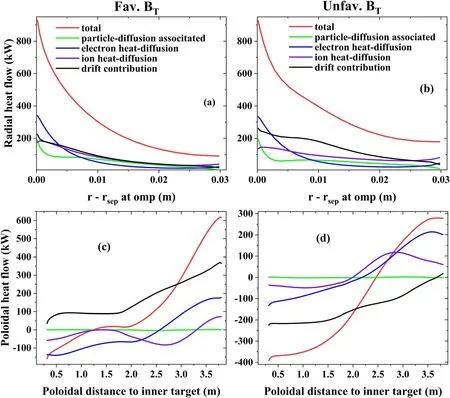
Figure 9.Components of the radial(poloidally integrated along flux surface)((a)and(b))and poloidal(radially integrated)((c)and(d))heat flows in the main SOL for favorable((a),(c))and unfavorable ((b),(d))BT at Γpuff=5.0 ×10¹⁹ s-1.Positive flow values in panels(a)and(b) represent the outward radial flow,and positive flows in panels (c) and (d) are towards the outer divertor region.
For plasmas with the LSN configuration in favorable BT,the magnetic drifts (i.e.vertical ∇B and curvature drifts) [3]drive ion carrying power heat from core to SOL through the bottom of the flux surface (figure 10).In the magnetic equilibrium used for this work (figure 2(a)),the component of magnetic drifts,directing across flux surfaces,in the lower outer quadrant is larger than that in the lower inner quadrant[39],due to the relatively large lower-triangularity (δl=0.560).Hence,cross-separatrix ion and heat flux from core to SOL through the lower outer quadrant of the flux surfaces is much larger than that through the lower inner quadrant of the flux surfaces (figure 12(a)),which can be a good explanation for the observation that heat flux from the upstream SOL into the outer divertor region (POD) is much larger than that into the inner divertor(PID).A part of the cross-separatrix ion/heat flow from the bottom goes back to the top through the P-S path[3],but the rest flows towards the divertor target.Both the inboard and outboard P-S flows,closing the magnetic drift flow,are disrupted by plasma particle flows moving towards the targets to provide recycling,leading to the appearance of up-down asymmetry in plasma pressure(Ptot),as manifested by the drop of Ptotat the top compared with that at IMP/OMP.In the SOL region below OMP,particles move from core to SOL,mainly driven by magnetic drifts,and finally arrive at outer plate.Above OMP,particle flow follows the classical P-S pattern,i.e.those core-to-SOL particles in the lower-outer quadrant go back to the upperouter quadrant and move into core again.Plasma ion flow in the high field side (HFS) follows a mechanism analogous to that in the low field side (LFS).
Further increase of Γpuffduring detachment will make the power entering into divertor region to be insufficient for ionization.Besides,energy required for per ionization event rises during detachment,as plasma in the divertor region gets colder and more excitation collisions occur before ionization [32].Hence,the roll-over of total target ion flux occurs further into detachment(figures 7(a)and(b)),due to the reduction of divertor ion source.In our simulations,volumetric recombination,which can be an effective ion sink in adequate divertor plasma conditions (Te<1 eV and ne>1020-m3[32]),remains small further into detachment process.According to [31,32],target pressure (Pt) loss is required for the roll-over of target ion current.In TCV[32],Ptreduction is found to be driven by both the volumetric momentum loss [3,31] and the reduction of upstream pressure (Pu),and the latter is considered to be crucial for understanding detachment.In our simulations,Pureduction also occurs during detachment (figure 12).Since the inner target plate is much easier to be detached,Pureduction at the HFS is found to be larger than that at the LFS.This inout asymmetry of plasma pressure loss along the flux surface tends to drive a convective poloidal SOL heat flow from the LFS towards HFS(figure 12(c)),compensating the neon caused power radiative loss at the HFS.Hence,during detachment as Γpuffincreases further,power flow from upstream into the inner divertor region (PID) tends to be insensitive to the increase of Γpuff;while that into the outer divertor region (POD) decreases rapidly (figure 7(c)).Physics reasons for Pureduction during detachment have been explored in previous analytic and modeling studies[40-42].To profoundly understand Pureduction and its influence on core plasma performances during detachment in EAST,deliberately designed experiments and integrated core-edge modeling will be performed in future.
As for plasmas with LSN configuration in unfavorable BT,magnetic drifts drive plasma ions carrying power from core to SOL through the top of the surfaces(figure 11).Some of the core-to-SOL plasma ions carrying power heat returns to core again through the separatrix at bottom of flux surface,which tends to decrease power flow into the divertor region;while some transports from the top to divertor target.From figure 11,which illustrates the main ion particle flux in the calculation region for plasmas with unfavorable BTat relatively low level of Γpuff(Γpuff=5.0×10¹⁹s-1),the radial ion flux from SOL to core at the LFS tends to be larger than that at the HFS.That is,fraction of power heat carried by particles returning to core at the LFS is larger than that at the HFS.Hence,heat flux into the inner divertor is larger than that into the outer one.Similar to that in favorable BT,as divertor plasma enters into detachment,upstream pressure(Pu) loss will be caused.Pureduction increases with further cooling of divertor plasma.Besides,Pureduction in the colder plasma region at the LFS is larger than that in the hotter plasma region at the HFS.This in-out asymmetry in Pureduction drives a convective SOL heat flux from the HFS to LFS along the flux surface (figure 12(d)),compensating the power radiative loss by neon at the LFS.Hence,heat flux into the outer divertor region is much insensitive to the increase of Γpuff,while heat flux into the inner divertor decreases rapidly as Γpuffincreases (figure 7(d)).Consequently,the required neon seeding rate for the onset of divertor detachment at the HFS is larger than but close to that at the LFS.The SOL heat flow,emerging due to in-out asymmetry in Pureduction,is found to be critical for understanding detachment and asymmetry observed in EAST.
3.3.Neon impurity transport
As described above,neon seeding tends to give drastic radiative power loss in the core and SOL,one reason for which may lie in the divertor leakage/retention of neon impurity.Hence,this section will focus on neon impurity transport in the divertor/SOL.Recent investigation on impurity transport revealed that the leakage efficiency of impurity from the divertor region of a tokamak is determined by the relative locations of impurity ionization source from neutrals and the stagnation-point for the poloidal velocity of impurity (upol,imp) [6].It is found that upol,impcan be estimated by adding the poloidalE×Bdrift velocity to the poloidal projection of parallel impurity velocity (i.e.(Bθ/B).u‖,imp),and the latter can be calculated based on the impurity force-balance equations in the parallel direction [3,6].Apart from providing the difference between the poloidal projection of u‖,imp(i.e.(Bθ/B).u‖,imp)and upol,imp,drifts can also contribute to upol,impvia affecting the parallel main ion (D+) velocity(u‖,D),since u‖,impdepends onu‖,Dvia parallel projection of impurity force balance.Besides,u‖,Dis tightly connected to the direction of toroidal magnetic field (BT) (equally to the direction of P-S flow).To investigate drift effects on neon impurity transport in the divertor/SOL of EAST with favorable/unfavorable BT,main characteristics of neon ionization source from neutrals and of neon particle flux pattern have been analyzed.
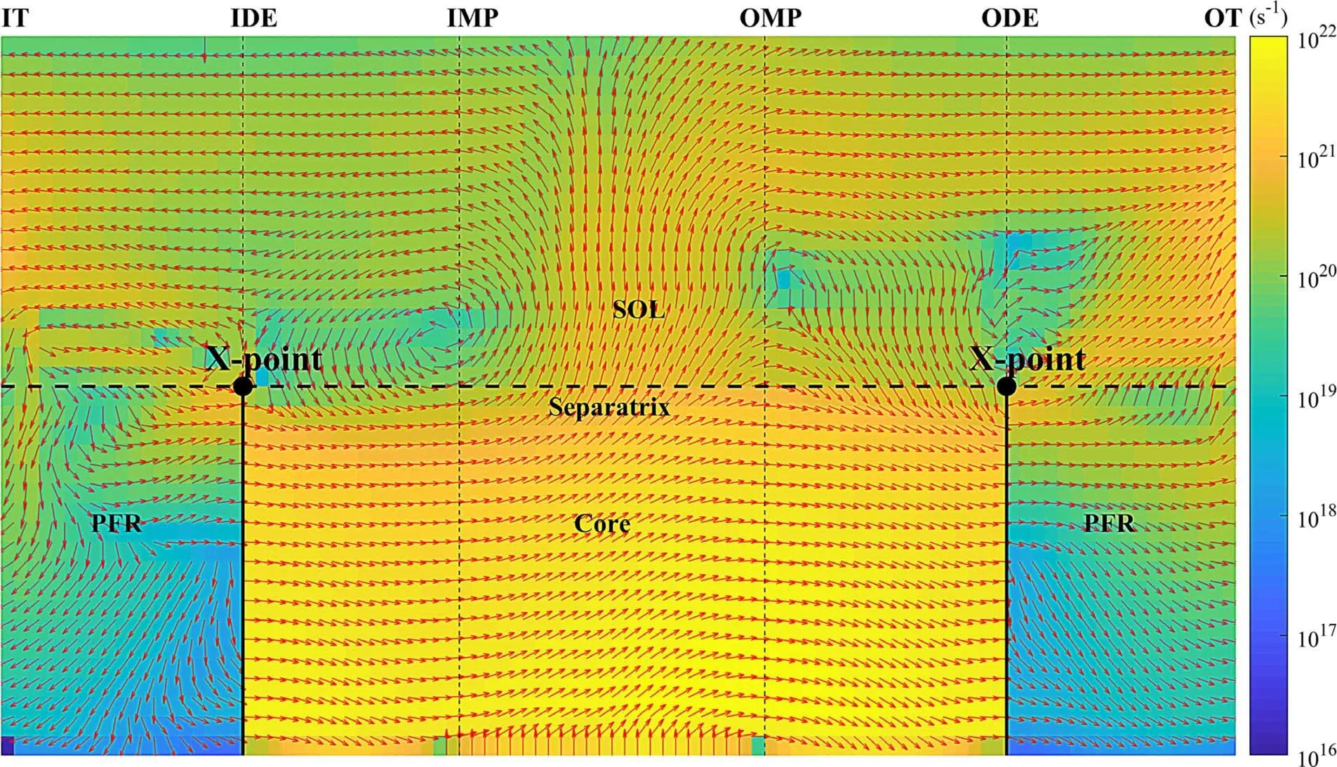
Figure 11.Similar to figure 10 but for the unfavorable BT case at Γpuff=5.0×10¹⁹ s-1.

Figure 12.Poloidal profiles of plasma pressure(P)and radial heat flow along the SOL flux tube of~2 mm radial distance to the separatrix at OMP,for favorable(a)and unfavorable(b)BT at different Γpuff,together with the radially-integrated poloidal SOL heat-flow for favorable(c)and unfavorable (d) BT at different Γpuff .Positive flow values in panels (a) and (b) represent the outward radial flow,and positive flows in panels (c) and (d) are poloidally directed towards outer divertor region.
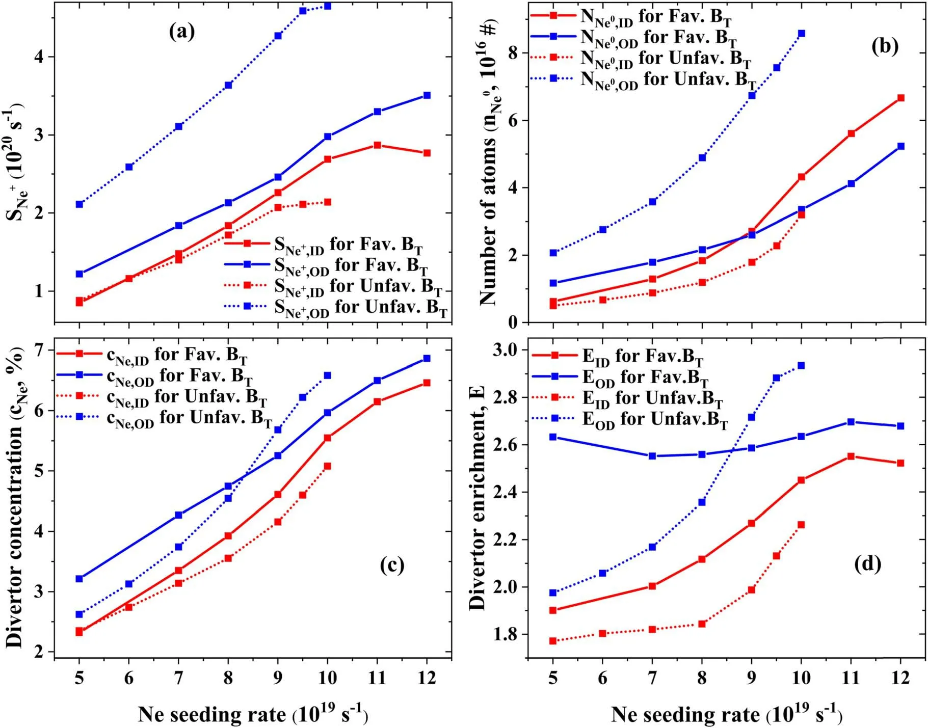
Figure 13.Total neon ionization source(in s-1)from atoms SNe+(a)and number of neon atoms (b),neon impurity concentration(cNe)(c) and neon enrichmentcNe,div/cNe,core (d) in the in the inner divertor (in red) and the outer one (in blue) for favorable (solid lines) and unfavorable (dotted lines) BT,plotted against the neon seeding level.
(a)Divertor leakage/retention of neon for favorable BT
Firstly,the favorable BTcases will be focused on.Figure 14 shows the typical SOL neon ion-flux-pattern in favorable BTat relatively low and high levels of neon seeding rate (Γpuff).From figure 14,whenΓpuffis relatively low(Γpuff=5.0 ×10¹⁹s-1),stagnation-point for poloidal neon ion velocity(upol,Ne)at the HFS is located quite near the inner target,especially for the near SOL,which may provide the neon ions with a high opportunity to leak from the inner divertor region;while at the LFS,most of the SOL region has no stagnation point of poloidal neon ion velocity,and thus neon ions can only leak from the outer divertor through the X-point.With Γpuffincreased to be relatively high(Γpuff=1.2×10²⁰s-1),the stagnation point of upol,Neat the HFS shifts away from the target to the upstream evidently;while at the LFS the stagnation point of upol,Neseems to be very insensitive to the level of Γpuff.To investigate the detailed influence of Γpuffand drifts on neon impurity leakage/retention in both divertors,poloidal profile of upol,Neand that ofare plotted in figure 15.
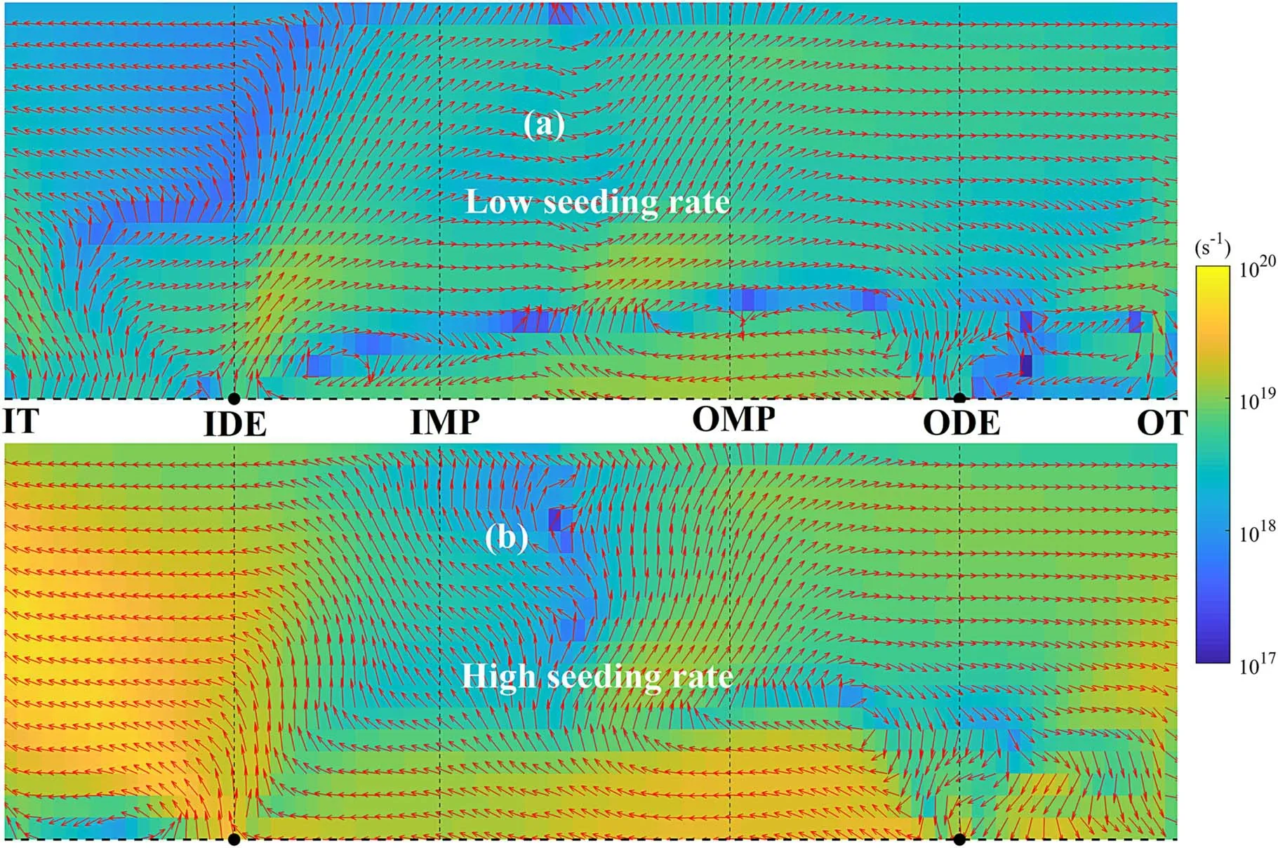
Figure 14.Typical SOL flow pattern of neon ion flux (summed over all the charge states) in favorable BT at relatively low(Γpuff=5.0×10¹⁹ s-1) (a) and high (Γpuff=1.2×10²⁰ s-1) (b) levels of neon seeding rate.
From figure 15,we can see that,in accordance with that in[6],the poloidal neon velocity upol,Necan be approximately calculated by adding the poloidal projection of parallel velocity for neon (u‖,Ne.Bθ/B)to the poloidalE×Bdrift velocity (vpol,exb,common for all ions).TheE×Bdrift contributes much to upol,Ne,especially in the main SOL of plasmas at relatively low levels of Γpuff.From the comparison between figures 15(a) and (b),withΓpuffincreased to be relatively high (Γpuff=1.2×10²⁰s-1),contribution of poloidalE×Bdrift (vpol,exb=Er/B,[3])to upol,Neseems to be decreased due to the decrease of radial temperature gradient (figure 5) on which Erdepends.The parallel neon ion velocityu‖,Neis calculated based on the parallel force balance equation and averaged over all the charge states (densityweighted),by referring to [6].In all the simulation cases,thermal force(Fth)approximately balances friction force(Ffr),i.e.Fth≈-Ffr,(figure 16),and thus the other terms (e.g.the pressure gradient,inertia and electric forces) are less important.
According to [33,43,44],the difference betweenu‖,Dandu‖,Neis given by:
Here,cfris the friction coefficient,cfr∝nD/T3/2(nDis the main ion(deuterium)density).Therefore,the ratio of thermal force and friction coefficient compensates the background plasma flow at the position of stagnation-point foru‖,Ne(i.e.u‖,Ne=0):
Basically,Fthshifts the position of stagnation point foru‖,Netowards the divertor plate and thus tends to decrease the retention of impurity ions in divertor region.WithFth∝∇T,one obtains
From equation (4),the increase of plasma density and the decrease of temperature,caused by neon seeding,reduce the effect of thermal force due to the reduction of,moving the stagnation point for impurity towards the that for plasma ion and further away from the target.
However,as described above,with Γpuffincreased from relatively low to high,position of stagnation-point for poloidal neon velocity upol,Nemoves from the divertor region towards the upstream at the HFS,but remains to be almost unchanged at the LFS (figures 14 and 15(a) and (b)).The insensitivity of neon impurity stagnation-point to the level of neon seeding rate at the LFS can be explained as follows.From figures 15(a) and (b),when Γpuffis relatively low,poloidalE×Bdrift in most of the outer divertor region is directed towards the outer target,and thus shifts the position of stagnation point for poloidal neon velocity upol,Neaway from the target;while when Γpuffis increased to be relatively high,the poloidalE×Bdrift in the outer divertor region is directed away from the outer target,which shifts the position of stagnation-point for upol,Netowards the outer target.That is,at the LFS,the decreased effects of thermal force caused by the increase ofΓpuffseems to be compensated by the effect of poloidalE×Bdrift.The reversing of poloidalE×Bdrift,equally the reversing of Er,in the near SOL at the LFS is caused by the significant reduction of temperature near the separatrix,asΓpuffincreases (figure 5).

Figure 15.Poloidal neon ion velocity upol,Ne,poloidal projection of parallel velocity for neon and deuterium(bx·u‖,Ne and bx·u‖,D,bx=Bθ /B)poloidal E×B drift velocity,and the strength of neon ionization source (in -s 1) from atoms in the near SOL (on the flux tube of~2 mm radial distance to separatrix at OMP) for favorable ((a) and (b)) and unfavorable ((c) and (d)) BT at relatively low (Γpuff=5.0 ×10¹⁹ s-1)((a),(c))and high((b),(d))neon puffing rate.For favorable/favorable BT,the high seeding rate is set to be 1.2 ×10 20/1.0×1020 s-1.The parallel velocity for neon is averaged over all charge states(density-weighted),by referring to[6].Positive value of velocity means that the velocity is directed towards the outer target.
From figure 15(a) for relatively low levels of Γpuff,although the strong ionization front is located quite near the inner target,strength of neon ionization source above the position of stagnation-point for poloidal neon velocity is also significant.Consequently,a large portion of neon ions moves upstream after the ionization.The consequent remarkable leakage of neon from the inner divertor can be one of the main reasons for the high radiation power in the core and SOL (figure 8).In contrast,at the LFS,most of the neon atoms are ionized below the position of stagnation-point for poloidal neon velocity,and thus only a small portion of neon ions leak from the outer divertor through the X-point after the ionization.Besides,E×Bdrift velocity makes the biggest contribution to the poloidal neon velocity upol,Nein the most of main SOL,driving the neon impurity ions from the inner divertor towards the outer one through the SOL (figure 14)and compensating theE×Bdrift driven neon ion flux from the outer divertor region towards the inner one through PFR.In our simulations,the order of magnitude for the integrated neon flux from the outer divertor to inner one through the PFR (figure 17) is found to be the same as that for the integrated strength of neon ionization source from atoms(figure 13(a)),but can be largely compensated by the outertarget directed ion flow (mainly driven byE×Bdrift)through the SOL,at relatively low levels of Γpuff.Hence,it is found that,in our simulation cases with favorable BTat low levels of Γpuff,the inboard divertor-enrichment of neon ions ENe,defined as the ratio of the averaged divertor neon concentrationcNeto the averaged core neon concentrationcNe,core[34],is larger than the outboard ENe(figure 13(d)),due to the larger outboard ionization source and smaller outboard neon impurity leakage.Here,the averaged neon concentration in a region(e.g.inner/outer divertor,SOL,core)is defined as the ratio of the total number of neon particles in this region to the total number of electrons in the corresponding region.
As Γpuffincreases,the inner divertor enters into detached regime and the degree of detachment will be increased,so that neon ionization source from neutrals will extends from the divertor region towards the upstream due to the high ionization potential(21.6 eV).From figure 15(b)for relatively high levels of Γpuff(Γpuff=1.2×10²⁰s-1),a large fraction of neon atom ionization occurs above the inner divertor entrance due to the significant cooling of inner divertor.However,as described above,position of stagnation point for poloidal neon velocity upol,Neis quite sensitive to the level of Γpuffand will be shifted towards upstream due to the decreased effect of thermal force (Fth/cfr).Hence,proportion of neon neutrals ionized above the stagnation-point for upol,Ne,equally the divertor leakage of neon,in the HFS can be greatly reduced as Γpuffincreases.Consequently,neon enrichment in the inner divertor region increases as Γpuffincreases (figure 13(d)).Since,the outer divertor region remains to be attached in all the favorable BTcases at different Γpuff,most of the neon ionization source from neutralsis located in the divertor region.Besides,as introduced above,the stagnation point of upol,Neis quite insensitive to the level of Γpuffand far from the outer target.As a result,neon enrichment in the outer divertor seems to be very insensitive to neon seeding rate(figure 13(d)).
(b)Divertor leakage/retention of neon for unfavorable BT
Figure 18 depicts the SOL neon-ion-flux in unfavorable BTat relatively low and high levels of Γpuff.From figure 18,when Γpuffis relatively low (Γpuff=5.0×10¹⁹s-1),the stagnation point of upol,Nein the near SOL can be located inside both the inner and outer divertor regions,due to the combined effects of thermal force(see the difference between u‖,Dand u‖,Nein figure 15(c)) andE×Bdrift.With Γpuffincreased to be as high as1.0×1020s-1,the position of stagnation point for upol,Nein some of the near SOL will be shifted away from the inner target,but for the region quite near the separatrix the position of stagnation point for upol,Neis still quite near the inner target.In contrast,position of the stagnation point for upol,Neat the LFS is shifted away from the outer target.In the far SOL,due to the fact that effect of thermal forceis decreased and that poloidalE×Bdriftis very small (small value of Erin the far SOL for unfavorable BTcan be found in in figure 4(a)),flow pattern of neon particle flux is quite similar to that of deuterium particle flux.This can be demonstrated by the comparison between figures 11 and 18.Hence,some of neon particles leaked from the divertor through the near SOL return from the top to the divertor region again through the far SOL.
From figure 15(c),in plasmas with unfavorable BTat relatively low levels of Γpuff,neon ionization source from neutrals at the LFS and that at the HFS are concentrated in the divertor region near the target,so that the leakage of neon ions from the divertors only occurs in the near SOL with the stagnation point of upol,Nebeing located quite near the target.Neon ion flux returning from the top to the outer divertor,through the far SOL,tends to be larger than that to the inner divertor.The integrated poloidal neon ion flux from the inner divertor to the outer one through the PFR(figure 17)is much less than the integrated neon ionization from atoms(figure 13(a)).Hence,the inboard neon diverter enrichment tends to be larger than the outboard neon divertor enrichment,mainly due to the much stronger outboard neon ionization source (figure 13).

Figure 18.Similar to figure 14,but for unfavorable BT at relatively low (Γpuff=5.0×10¹⁹ s-1) (a) and high (Γpuff=1.0×10²⁰ s-1) (b)levels of neon seeding rate.
From figure 18(b),with Γpuffincreased to be as high as 1.0×10²⁰s-1,at the HFS,the shift of neon ionization source front away from the target leads to a strong leakage of neon ions from the inner divertor through X-point (figure 18(b),since the ionization source front,there,is located further from the inner target than the position of stagnation-point for poloidal neon velocity,in the region near the separatrix.In contrast,at the LFS,the neon ionization source from neutrals is concentrated in the outer divertor region and the stagnation point of upol,Neis shifted out of the divertor region,so that most of the neon ions after ionization will be entrained in the outer divertor region.Integrated neon flux from the inner divertor region to the outer one through the PFR becomes to be almost negligible as Γpuffincreased to be relatively high(figure 17),due to the reversing ofE×Bdrift flux in the near PFR (with respected to radial distance to separatrix)(figure 19).However,the significant decrease of target plasma temperature near the separatrix tends to invert the radial electric field from the outwards to inwards directions(figures 15(c) and (d)),which drives a strong neon ion flux from the inner divertor region to the outer one in the near SOL (figure 18(b)).Besides,the strength of neon ionization source in the outer divertor region is much stronger than that in the inner one (figure 13(a)).Consequently,concentration/enrichment of neon impurity in the outer divertor region tends to be larger than that in the inner one (figure 13(d)).
As described in section 3.1,in plasmas with unfavorable BTat Γpuff=1.0×10²⁰s-1,the so-called X-point electric potential well will be formed.Figure 19 shows the deuterium ion flux plotted in the computational meshes for unfavorable BTat this level ofΓpuff.From the comparison between figures 19 and 11,the formation of X-point potential well reverses both the poloidal and radialE×Bdrift flows in the near PFR and near SOL at both the LFS and HFS,due to the reversing of electric field(E)near the X-point.Hence,similar to that in [8],the potential well tends to compress/widen radial density profile in inner/outer divertor,which can be demonstrated by comparison between the radial width of target density profile for favorable BT(blue solid lines in figures 5(b) and (c)) and that of target density profile for unfavorable BT(blue dotted lines in figures 5(b) and (c)),at relatively high level of neon seeding.Details about the influence of X-point potential well on radial and poloidal particle transport in the divertor region can be found in [8].
4.Conclusions
Figure 19.Similar to figures 10 and 11,but for the unfavorable BT case at Γpuff=1.0×10²⁰ s-1.
Seeding impurities into divertor region for achieving semidetached/detached regimes has been considered as an essential tool to control heat loads on the plates at a tolerable level,in the high-power operation of both the current and future tokamaks,such as EAST and ITER.To improve the compatibility of detached divertor operation with high performance core plasmas,a profound understanding of impurity-seeded plasmas is indispensable.Hence,the comprehensive SOLPS-ITER code has been used to numerically investigate drift effects on divertor detachment and asymmetry and on impurity transport in EAST during neon seeding with favorable and unfavorable toroidal magnetic field directions (BT).
Firstly,distribution of electrostatic potential and field has been analyzed,to make sure that they are correctly described and to better understand the drift-driven processes.Results demonstrate that divertor/SOL electric potential profile for favorable BTfollows the classical picture,i.e.the parallel electric field directing towards the target plates and the radial electric field away from the separatrix;while for unfavorable BT,the so-called X-point potential well,which reverses the electric field in the divertor region near the X-point,forms at high neon seeding rates.In consistency with results in[8],the electric potential well emerges in deeply detached plasmas,with Pfirsch-Schlüter currents contributing predominately to the parallel current,and tends to compress/widen radial density profile in the inner/outer divertor.The radial electric field (Er) in the confinement region of EAST is found to be close to its neoclassical value,which is similar to that for ITER [28] and for some other current tokamaks [17].In the outer core,Erfor unfavorable BTis smaller than that for favorable BT,because of the smaller neoclassical contribution related to radial density gradient.
After that,the combined effects of neon seeding and drifts on divertor detachment and asymmetry are focused on.Results reveal that,in accordance with the experimental observations in EAST [10],for favorable BT,detachment onset is highly asymmetric between the inner and outer divertors,i.e.the inner divertor is much more easily to be detached than the outer one.In-out asymmetry existed in the required neon puffing rate for the onset of divertor detachment for unfavorable BTis much less than that for favorable BT.Further analysis indicates that apart from the well-knownE×Bdrift particle flow from one divertor region to the other through the PFR,plasma heat flow through the main SOL,particularly the total power into the divertor region from the upstream,is also a critical parameter affecting divertor detachment and asymmetry.The SOL heat flow is much more asymmetrically distributed between the HFS and LFS for favorable BTthan that for unfavorable BT.During detachment,upstream pressure (Pu) reduction,which has also been experimentally observed in TCV [32] and COMPSS [45],occurs in the simulation.Pureduction is more significant in the colder plasma side than that in the hotter one,and tends to drive a convective SOL heat flow from the hotter side towards to colder one.During detachment,the SOL heat flow,emerging due to the in-out asymmetry in Pureduction,compensates the radiative power loss at the colder side,and thus power flow from the upstream towards the colder divertor becomes to be insensitive to neon seeding level while that towards the hotter divertor decreases rapidly.This can be a good explanation for the experimental observation that in unfavorable BTthe onset of divertor detachment between inner and outer divertor becomes to be nearly balanced.
To better understand the simulated result that power radiative loss during neon seeding tends to be drastic in the core and SOL,drift effects on neon impurity transport in the divertor/SOL of EAST with favorable/unfavorable BThave been studied for the first time.Results indicate that position of the stagnation-point for poloidal neon ion velocity profile,as a key element determining neon leakage/retention in divertor,can be greatly affected by the P-S flow direction,E×Bdrift and by divertor operation regimes depending on neon seeding level.As a result,neon impurity leakage from divertor is found to be much sensitive to BTdirection and to neon impurity seeding level.The latter can also affect the neon ionization source distribution,which is another key factor determining neon divertor retention/leakage.E×Bdrift contributes a lot to poloidal neon impurity ion velocity,especially in the main SOL,and thus could not be canceled in simulations on impurity transport in EAST.In attached plasmas with relatively low seeding rate,the stagnation-point for neon poloidal velocity (upol,Ne) locates quite near the target plate so that a large fraction of neon neutrals can be ionized above it and then leak from the divertor region.As neon seeding rate increases,stagnation-point for poloidal neon velocity shifts towards the upstream,and the proportion of neon neutrals ionized above the stagnation point can be decreased,which is consistent with results in [6].
Although,modeling work described in this paper is not performed based on specific experiments,it can greatly facilitate the understanding of divertor detachment and asymmetry as well as impurity transport in EAST and can serve as a reference for future numeric simulations performed more closely related to experimental regimes.
Acknowledgments
This work was supported by National Natural Sciences Foundation of China(Nos.12075052,12175034 and 12275098)and National Key R&D Program of China(Nos.2018YFE0309103,2017YFE0301100 and 2017YFE0301104).The authors are very grateful to the EAST team for all the support.Numerical computations regarding this work were performed on the ShenMa High Performance Computing Cluster in Institute of Plasma Physics,Chinese Academy of Sciences.
ORCID iDs
猜你喜欢
杂志排行

Plasma Science and Technology的其它文章
- High-order field theory and a weak Euler-Lagrange-Barut equation for classical relativistic particle-field systems
- Design of new resonant magnetic perturbation coils on the J-TEXT tokamak
- Non-invasive optical characterization and estimation of Zn porosity in gas tungsten arc welding of Fe-Al joints using CR model and OES measurements
- A study of grid failure mode drivers and methods for accelerated life testing of a 30cm diameter ion thruster
- Research on degradation mechanism of trichlorobenzene and Hg0 by nonthermal plasma catalysis
- Ionization wave propagation and cathode sheath formation due to surface dielectricbarrier discharge sustained in pulsed mode