Exploration on 2D DOA Estimation of Linear Array Motion:Uniform Linear Motion
2023-11-18JianhongChuZhiZhangYuGuo
Jianhong Chu ,Zhi Zhang,* ,Yu Guo
1 School of Information and Communication Engineering,Beijing University of Posts and Telecommunications,Beijing 100876,China
2 State Key Laboratory of Networking and Switching Technology,Beijing University of Posts and Telecommunications,Beijing 100876,China
*The corresponding author,email: zhangzhi@bupt.edu.cn
Abstract: Generally,due to the limitation of the dimension of the array aperture,linear arrays cannot achieve two-dimensional(2D)direction of arrival(DOA)estimation.But the emergence of array motion provides a chance for that.In this paper,a generalized motion scheme and a novel method of 2D DOA estimation are proposed by exploring the linear array motion.To be specific,the linear arrays are controlled to move along an arbitrary direction at a constant velocity and snap per fixed time delay.All the received signals are processed to synthesize the comprehensive observation vector for an extended 2D virtual aperture.Subsequently,since most of 2D DOA estimation methods are not universal to our proposed motion scheme and the reduced-dimensional (RD) method fails to handle the case of the coupled parameters,a decoupled reduced-complexity multiple signals classification(DRC MUSIC)algorithm is designed specifically.Simulation results demonstrate that: a)our proposed scheme can achieve underdetermined 2D DOA estimation just by the linear arrays;b) our designed DRC MUSIC algorithm has the good properties of high accuracy and low complexity;c) our proposed motion scheme with the DRC method has better universality in the motion direction.
Keywords: 2D DOA estimation;linear array motion;reduced complexity;synthetic aperture
I.INTRODUCTION
Direction of arrival (DOA) estimation is one of the significant parts of array signal processing,which has been opened up in many fields,such as wireless communication,public safety and so on [1–4].In the past few decades,the research goal of DOA estimation mainly focuses on the array configuration and the design of algorithm for higher estimation accuracy,lower complexity as well as higher degree of freedom(DOF).Generally,the extension of array aperture in size and dimension can realize better performance.
In one-dimensional (1D) DOA estimation,many sparse linear arrays with convenient configuration,such as coprime linear array (CLA) [5],nested linear array (NLA) [6],augmented coprime linear array(ACLA)[7],and their unfolded versions[8],have been proposed for extending the size of the array aperture.For achieving two-dimensional (2D) DOA estimation with more practicality,many 2D arrays,such as uniform planar array (UPA) [9],coprime planar array (CPA) [10],L-shaped array [11],parallel array[12,13],and their unfolded versions[14,15],are also developed by extending the aperture dimension.Summarily,the linear arrays with simple configuration mainly bring the extension in the aperture size but generally cannot achieve 2D DOA estimation.Conversely,the 2D arrays can achieve the extension of the aperture dimension for 2D DOA estimation,but they need to place many sensors as cost and have more complex configuration than the linear arrays.Thus,“how to achieve 2D DOA estimation by linear arrays?”is attractive.
Recently,the array motion techniques[16–18]have been explored to improve the virtual effective array aperture in much literature and attain increasing interest.As one of the effective methods of improving the array aperture,the array motion techniques may be utilized to extend the dimension of the array aperture for 2D DOA estimation with 1D linear arrays.However,the existing literature mainly focuses on the 1D array motion with improved aperture size rather than the aperture dimension.Specifically,[19]confined the synthetic steps to only half wavelength in the 1D array motion for more practicality.However,the increase of DOF is limited.In [20],shifted synthetic steps were used to increase the DOF threefold by exploring the 1D array motion.Moreover,in[21,22],on the basis of the 1D array motion,a novel dilated array mounted on the moving platform was proposed for higher uniform DOF and less mutual coupling.Furthermore,Luoet al.[23]extended the 1D array motion technique into the linear receive array of the bistatic MIMO radar for expanding the visual aperture.But the array aperture extension is also limited and the receive array still cannot achieve the simultaneous azimuth and elevation estimation.
In addition,in [24],an improved 2D DOA estimation method was proposed by exploring the rotation of unmanned aerial vehicle(UAV)equipped with NLA.The observations received at different rotation angles are separately processed to estimate the parameters.However,the system motion is discontinuous and some effect factors like Doppler shift are unconsidered during the motion period,so the array aperture is not fully fused and the DOF is limited.Summarily,the aforementioned methods cannot achieve highly effective 2D DOA estimation just by the linear arrays.
On the other hand,since the arrays can be mounted on vehicle-attached,ship-based,and air-borne moving platforms,both the practical motion scenario and the installation of arrays may result in the undesired motion direction.For example,the platform may have the size limitation and the practical motion routes are various.Thus,it is necessary to analyze the case that the motion direction has an arbitrary angle with the line placing the linear arrays.At the best of our knowledge,there is no literature working on the generalized motion direction to further extend the array aperture.
Motivated by the above discussions,in this paper,we consider that linear arrays linearly move at a constant velocity along the direction having an angle with the line placing the linear array.The linear array is set to snap at fixed time interval during the motion period.Consequently,the received signals at different time are synthetically processed to extend the dimension of the virtual array aperture.Then our proposed approach keeps the good property of simple configuration of linear array and,at the same time,realizes 2D DOA estimation.
Due to the 2D virtual array aperture,our proposed scheme can be viewed as the virtual planar array.Nevertheless,the structure of the virtual planar array is uncommon and the issue of coupled parameters occurs except for the vertical motion case,to which the existing methods are not universal.As for 2D estimating signal parameters via rotational invariance techniques(ESPRIT)method[25],the uniform lags are needed to ensure the rotational invariance,which,however,cannot hold for arbitrary linear arrays and motion directions.In[26],the successive propagator method(PM)-based algorithm was proposed to reduce the computational complexity but without too much performance loss.But this method still needs the rotational invariance to realize the initial DOA estimation and has the same problem as the 2D ESPRIT.Although 2D PM[27]has the similar universality with the 2D multiple signal classification (MUSIC) algorithm [28],its approximation of the noise subspace still has a large gap from the real noise subspace in the motion scheme,which will easily cause the pseudo peak and even algorithmic failure.In[29,30],the RD methods were proposed for L-shaped arrays and the process of reduced dimension was achieved by just using the observations of one of the subarrays.But these methods have strong dependence on the L-shaped arrays structure and cannot fully use observations in other planar arrays.In[31–33],the RD methods were developed for angle estimation of MIMO radar,DOA estimation of CPA,and source location of uniform linear array(ULA),respectively.However,they all need the premise: oneby-one relationship between the subarrays manifolds and the estimating parameters.Pertaining to our proposed scheme,the parameters are coupled in a single array manifold,namely,parameters coupling,so the RD method fails to work.
To sum up,the above methods are not suitable for our proposed scheme and it is a challenge to develop an effective method adapting to our generalized motion scheme.For handling the coupled cases,we propose a decoupled reduced-complexity MUSIC (DRC MUSIC) algorithm in this paper,which mainly contains two steps: one is the decoupling process,the other is transforming the 2D spectral peak searching into 1D searching.DRC MUSIC not only greatly reduces the computational complexity but also achieves high resolution with the full use of noise subspace.More importantly,the proposed DRC MUSIC method is universal to our generalized motion scheme.
To be more explicit,the main contributions of this paper are concluded as follows:
· The generalized scheme of the linear array motion for 2D DOA estimation is explored by making the array uniformly and linearly move along an arbitrary direction.With the basis of the synthetic aperture technique,the formation of the 2D virtual array aperture is mathematically illustrated and the synthetic signal model of virtual array is derived in this paper.Thus,our proposed scheme not only keeps the good property of simple configuration but also achieves 2D DOA estimation just by the linear arrays.
· To further clarify that our proposed scheme has universality in both motion direction and initial linear arrays,the synthetic signal models are derived for the representative linear arrays including ULA,NLA,and CLA,respectively.Thus,both the sparse arrays and dense arrays are readily suitable for our scheme under the arbitrary motion direction.Additionally,the virtual planar arrays and the higher DOF are achieved in our proposed scheme by creating more virtual elements.
· For realizing low-complexity and high-resolution DOA estimation,a new algorithm named DRC MUSIC is proposed by specifically designing the decoupling process to handle the case of the coupled parameters before carrying out the 2D DOA estimation.Necessarily and firstly,the parameters coupled in one of the subarrays manifolds are decoupled into two product items.Then Lagrange multiplier method can be adopted to derive the relationship between the two estimating parameters.Also,the noise subspace is fully used to improve estimation resolution and achieve automatic pairing of parameters.
· Finally,extensive simulations and analyses are carried out to evaluate the performance.The capacity of the underdetermined estimation is evaluated first.Then the estimation accuracy and the complexity are analyzed by comparing our DRC method with the other universal algorithms.In addition,we clarify the effect of the motion direction on the performance.Results demonstrate that our motion scheme can achieve underdetermined 2D DOA estimation just by the linear arrays and the proposed method has superiorities in accuracy and complexity as well as universality.
The rest of this paper is organized as follows.The synthetic signal model of linear array motion is presented in Section II.The synthetic processing techniques for the representative linear arrays(ULA,NLA,and CLA)are illustrated in Section III.The proposed DRC MUSIC algorithm,DOFs and the corresponding expression of CRB are given in Section IV,where the cases of the coupled parameters are also illustrated detailedly.Simulation results are provided in Section V and conclusions are summarized in Section VI.
Notations:We use lower-case letters,lower-case and upper-case bold characters to denote scalars,vectors and matrices,respectively.Besides,(·)T,(·)*,and (·)Hdenote the transpose,conjugate,and conjugate transpose of a vector or matrix,respectively.Kronecker Product and Hadamard Product are denoted by⊗and⊙,respectively.Meanwhile,means the maximum integer that is lower than or equal to scalara.The notation diag(·) stands for a diagonal matrix that employs the elements of the vector as its diagonal elements.
II.SYNTHETIC SIGNAL MODEL
The proposed motion scheme and the construction of the synthetic signal model are illustrated in this section.In addition,the effect of motion direction on the estimation accuracy is analyzed from the perspective of the variation of virtual array aperture.
2.1 Signal Model
Figure 1 shows the schematic of linear array motion.Consider that the initial array is a linear array withMsensors and the abscissa of sensor isdxmform=1,···,M,while the first sensor is reference point,i.e.,dx1=0.Without loss of generality,we make the linear array located at positivex-axis move along an arbitrary direction at a constant velocityv.Denote the angle between the positivex-axis and the motion direction asα.Due to symmetry,the angleαcan be confined as 0° <α <180°.
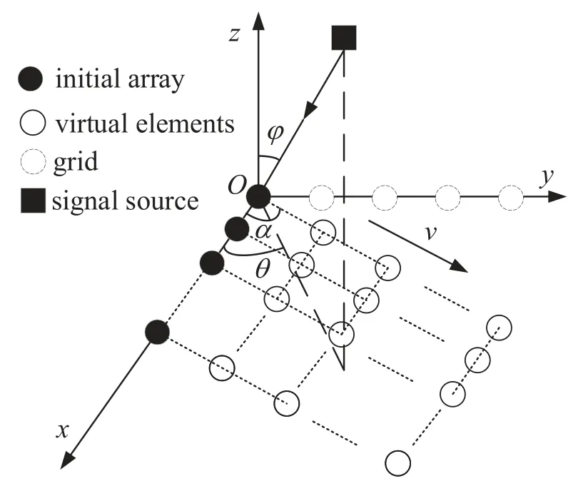
Figure 1. Schematic of array motion.
Suppose thatKfar-field narrowband signals with the same wavelengthλimpinge on the array,and thek-th incident signal is denoted assk(t),k=1,···,K.Like [15,32],introduce the parametersμk=cos(θk)sin(φk)∈[-1,1] andγk=sin(θk)sin(φk)∈[0,1],whereθk ∈[0°,180°] and
φk ∈[0°,90°] are thek-th azimuth and elevation,respectively.Similar to the analysis on the effect of Doppler shift in[18,19],the output of the linear array at timetis expressed as
wheref0=is the carrier frequency with electromagnetic wave propagation speedc,andpkis written aspk=μkcos(α) +γksin(α).n(t) is the white Gaussian additive noise vector with zero means and variance ofσ2.The array manifold ax(μk)is denoted
as
To be noted,the motion case presented in [16–23]can be regarded as a special situation of our proposed scheme when the offset angle is set asα=0°,and it can only resolve the azimuth estimation.
Moreover,the output of arrays at timetcan be transformed as
At timet+nτ,wherenis non-negative integer,the received signal of array becomes
As for narrowband signal,the itemsk(t+nτ)(t)exp(j2πf0nτ)holds.Thus,(4)can be rewritten as
By using the phase correction factor exp(-j2πf0nτ),we can gain the synchronized signal as
Like [16–18],we introduce time coherence period(TCP)to determine the total motion time and suppose that the motion distance isdduring the timeτ.Also,the sources waveforms and locations are supposed to be invariant over the period of array motion.By exploring the coherence time of signals,the references[21,34]had provided theoretical support for the feasibility of array motion.
DenoteN=and 0≤n ≤N,the comprehensive received signal using synthetic aperture process is given by
By taking(3)and(6)into(7),we have
Thus,the 2D virtual aperture and virtual planar array are achieved under the synthetic aperpture processing,and our proposed scheme has universality in motion direction.
To make the illustration of the above scheme clearer,a owchart is provided as Figure 2.
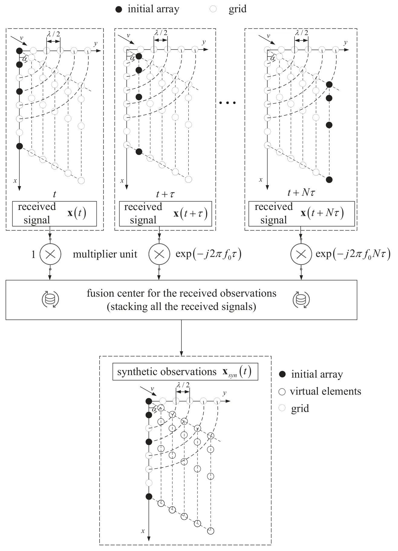
Figure 2. Flowchart of our proposed motion scheme.
2.2 Effect of Motion Direction on Aperture
In practical scenarios,due to the limitation of the equipment and the practical motion environment,the platform with arrays may not move along the desired direction.Thus,it is reasonable to introduce the offset angle to generalize the motion scheme.We will further analyze the variation of the virtual array aperture with the offset angle changing to show the effect of motion direction on the estimation accuracy.
According to[35,36],the performance of the angle estimation is proportional to the size of the array aperture and the array aperture of the planar array can be portrayed as the size of the area.So,under the given TCP,the constructed array aperture is represented as
where the notation∝means that the left is proportional to the right.Because the offset angle is confined as 0° <α <180°,the item sin(α) increases monotonically first and then decreases monotonically withα=90°as the cut-off point.Consequently,the array aperture follows the same rule and realizes the maximum value when the offset angle meetsα=90°.
Since the above analysis is qualitative,the specific numerical simulations will be given in subsection 5.4 for further verifying the effect of the motion direction on the performance quantitatively.
III.SYNTHETIC APERTURE PROCESSING FOR SPECIFIC CASES
In this section,on the basis of the above analyses,the synthetic aperture processing method is elaborated for some representative linear arrays to further clarify the universality of our proposed scheme.
3.1 The Case of ULA
In this part,the initial array is set as ULA withMsensors,whose inter-element spacingdis half-wavelength.Thus,the corresponding abscissa of sensors isdxm=(m-1)d.
As indicated in Figure 3,ULA is controlled to move at the distance of half-wavelength per timeτulaalong the motion direction.Then the timeτulaare calculated as.Meanwhile,the TCP is limited as TCPula=(M -1)τula,so the parameternis determined as 0≤n≤=M -1.
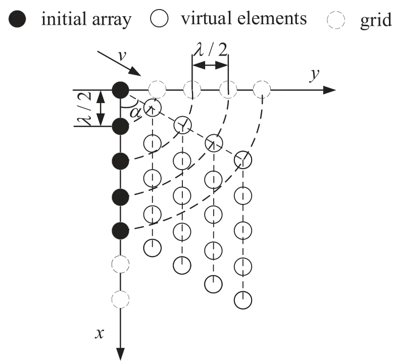
Figure 3.Schematic of ULA motion(vertical view),M=5.
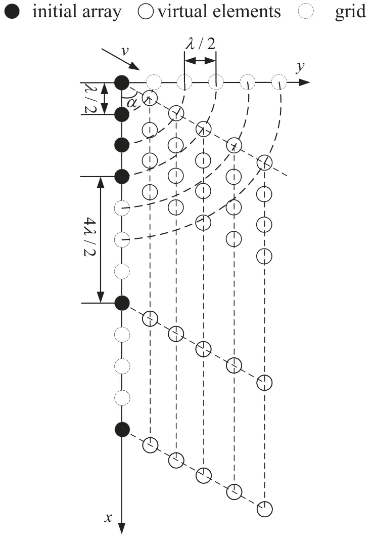
Figure 4.Schematic of NLA motion(vertical view),M=6.
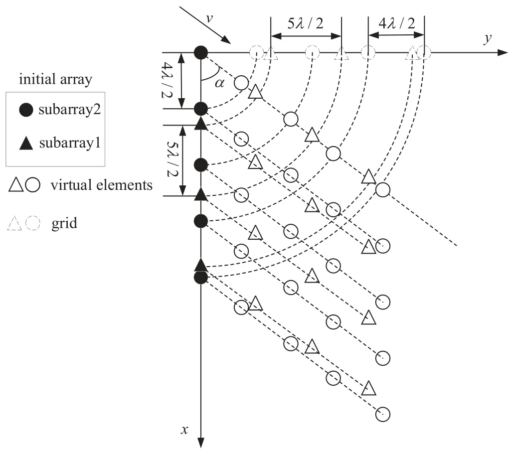
Figure 5. Schematic of CLA motion (vertical view),M1,cla=4,M2,cla=5.
Accordingly,the synthetic signal is formed as
3.2 The Case of NLA
In this subsection,we consider the initial array as NLA withMsensors,whose inter-element spacing is given by
3.3 The Case of CLA
In this part,the initial array is replaced as CLA consisting of two subarrays,i.e.,subarray1 withM1,clasensors,subarray2 withM2,clasensors.Because the first sensor is overlapped,the total number of sensors of CLA isM=M1,cla+M2,cla -1.Accordingly,the abscissa of elements isdxm ∈{{0,M1,cla,...,(M2,cla-1)M1,cla}∪{M2,cla,...,(M1,cla-1)M2,cla}}d.
Similar to the aforementioned synthetic aperture processing,the synthetic signal ofl-th subarray is written as
While our analyses are focused on the representative linear arrays,they can be readily extended to other linear arrays and even planar arrays.
IV.DOA ESTIMATION
Since the conventional MUSIC algorithm has high computational complexity and the other existing algorithms have no universality to our proposed motion scheme,in this section,we propose a DRC MUSIC method with high estimation accuracy and low computational complexity.Also,the closed-form expressions of CRB and DOFs are given.
4.1 Our Proposed DRC MUSIC Algorithm
Firstly,the covariance matrices of synthetic signals are respectively calculated by
The above covariance matrices are collectively denoted as,on which the eigenvalue decomposition(EVD)is conducted to gain the noise subspace ˆEnoise.Without loss of generality,other matrices and vectors are made the same denotations.
Define the functionY(μ,γ,α) as (24).As for the existing methods with low complexity,the items around the Kronecker product should be related to the estimated parameters one by one and the Lagrange multiplier method can be used to reduce the dimension of estimation.However,the parametersμandγare coupled in both aα,la(μ,γ,α) and aHα,la(μ,γ,α),so the RD method fails to work.The decoupling process is necessary for handling the problem.
Then(24)can be rewritten as
Since (26) is a quadratic function,(μ,γ,α)=1 is added to eliminate the trivial solution of aα,la(μ,γ,α)=0max(n+1)×1,where e1=[1,0,...,0]T ∈Rmax(n+1)×1.Moreover,the problem of minimizing spectral function is reconstructed as
Like the RD method [33],the Lagrange multiplier method is utilized to obtain the relationship between the estimating parameters.Then the cost function is constructed as
whereεis a constant.
Substituting(25)into(28)yields
Take the partial derivation of the cost function
Since the items e1and D(μ,α) are represented as e1=[1,0,...,0]Tand D(μ,α)=diag(■1,exp(-j2πμcos(α)),...,
We can further obtain bα,la(γ,α)=ρF-1(μ,α)DH(μ,α)e1,whereρis a constant andρ={(μ,α)F-1(μ,α)DH(μ,α)e1}-1.Moreover,bα,la(γ,α)can be derived as
Furthermore,the estimate ofμis obtained as
So far,the estimated value ofμkis achieved by 1D spectral peak searching.
Subsequently,we can gain the estimated values ofγkby (34).Furthermore,the above process can also make the estimates ofμkandγkautomatically paired.
Finally,the estimates of DOAs are obtained as
Notably,as for the CLA motion,we can make some improvements to further reduce the computational complexity.Because the ambiguous and the true DOAs form an arithmetic sequence,the searching range of parameterμis limited as
whereklis positive integer and 1≤kl ≤Mq,cla.The above (23) -(33) are employed to gain the estimated value ofμas.Then the rest of the estimation ofμcan be directly calculated by
whereis integer and-(kl-1)≤≤Mq,cla-(kl-1).
After conducting the above process for the two subarrays,respectively,we can obtain two sets of estimation ofμ.Define the difference functionfdas
Thus,the true estimation ofμis achieved by choosing the correspondingand,which are found by searching for the minimal value offd.That means
Subsequently,like [37],the synthetic signals of subarrays are jointly utilized to make full use of the autocorrelation and cross-correlation information.The received signal is constructed asSimilar to (23) and (34),the covariance matrix and the spectrum function are calculated to gain the true estimation ofγ.Then the parametersθandφare obtained by(35)and automatically paired.
For clearer explanation,the main steps of our proposed DRC MUSIC algorithm are summarized as Algorithm 1.
4.2 DOF
The number of DOF is consistent with the total number of elements and determines the number of the resolvable signal sources.Thus,the DOFs of ULA,NLA,and CLA in our proposed scheme are,and min(Ml,claMyl)with,l,q=1,2,l/=q,respectively.For clearer illustration and comparison,the DOFs of the different cases are listed in Table 1.Theoretically,our proposed scheme(case3)can obtain higher achievable DOF.

Table 1. Comparison of DOFs for different cases.
4.3 CRB
Under the cases of ULA and NLA,the direction matrices Asyn,ulaand Asyn,nlaare collectively defined as Asyn,la.
The signal covariance matrixcan be obtained by
Then define the matrix
According to[38–40],the CRB can be represented as
As for the CLA motion,due to the different mode of motion,the CRB is correspondingly modified.We denote a new direction matrix as
where Aα,cla,l=[aα,cla,l(μ1,γ1,α),...,aα,cla,l(μK,γK,α)],Axl=[axl(μ1),...,axl(μK)].Atis the output after removing the first row of the Aα,cla,2.Dml,cla(·) is the diagonal matrix that consists of theml,cla-th row of the matrix.
Similarly,according to[32,38,39],the CRB can be represented as
V.SIMULATION RESULTS
In this section,simulation results are presented to verify the performance of the proposed scheme with respect to estimation accuracy and computational complexity as well as universality.The arrays located atx-axis move at a constant velocityv=3 m/s.Consider that there areKfar-field narrow-band uncorrelated signal sources impinging on the arrays.The corresponding search step is set as Δμ=Δγ=0.0002.In the subsequent simulation results,since the classical 2D MUSIC algorithm,orthogonal propagator method(OPM) [27],and the modified OPM (mOPM) [41]have universality in array structure,they will be compared with our proposed DRC MUSIC algorithm to verify the superiority of our method.Also,the corresponding CRB curve is included.The root mean square error (RMSE) is adopted to assess the estimation accuracy and defined as
5.1 Capability of Achieving Underdetermined 2D DOA Estimation
In this subsection,the estimation results corresponding to the virtual planar arrays formed by initial arrays motion are presented to verify the capacity of achieving underdetermined 2D DOA estimation for our proposed scheme.
Under the cases of ULA,NLA,and CLA,the number of sensors is set asM=8(M1,nla=M2,nla=4,M1,cla=4,M2,cla=5).The corresponding TCP is limited as 7τ,19τ,and 16τ,respectively,on the basis of the analysis of Section III.The offset angleαis arbitrarily selected asα=30°.Estimation results are scattered in Figure 6,whereK=10,and the real DOAs are arbitrarily selected in the figures.Also,the SNR and the number of snapshots are set as 8 dB andF=800,respectively.The simulation results depict that our proposed scheme can accurately estimateK=10 signal sources just byM=8 sensors.Thus,the underdetermined 2D DOA estimation is realized.
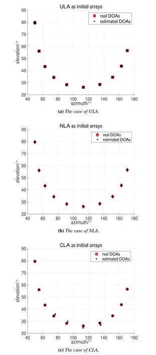
Figure 6. The results of underdetermined 2D DOA estimation.
5.2 Simulation Results on Estimation Accuracy Performance
Simulation results of estimation accuracy for various initial arrays such as ULA,NLA,and CLA are given in this subsection.
The number of sensors,the corresponding TCP and the offset angle are the same as the settings in subsection 5.1.The DOAs ofK=2 sources are (θ1,φ1)=(40.23°,20.25°) and (θ2,φ2)=(60.58°,80.63°) with (μ1,γ1)=(0.2642,0.2235)and(μ2,γ2)=(0.4847,0.8594).The relationship between the RMSE and the signal-to-noise ratio(SNR)is plotted in Figure 7,where the SNR varies from-10 dB to 10 dB with step 2 dB,and the impact of the number of snapshots on RMSE performance is shown in Figure 8,where the number of snapshots ranges from 20 to 500.Also,Figure 7 and Figure 8 fix the number of snapshots and the SNR atF=2048 and SNR=10 dB,respectively.With the increase of SNR or the number of snapshots,the curve of DRC MUSIC is around the curve of MUSIC and much lower than the OPM s and mOPM s curves.Due to the uncommon parallelogram-shaped array structure,both the OPM and mOPM fail to approach effective noise subspaces even if the mOPM achieves denoising by the spline interpolation method.Thus,our proposed method keeps the superiority of high estimation accuracy under the full use of noise subspace and has better universality as well as robustness.
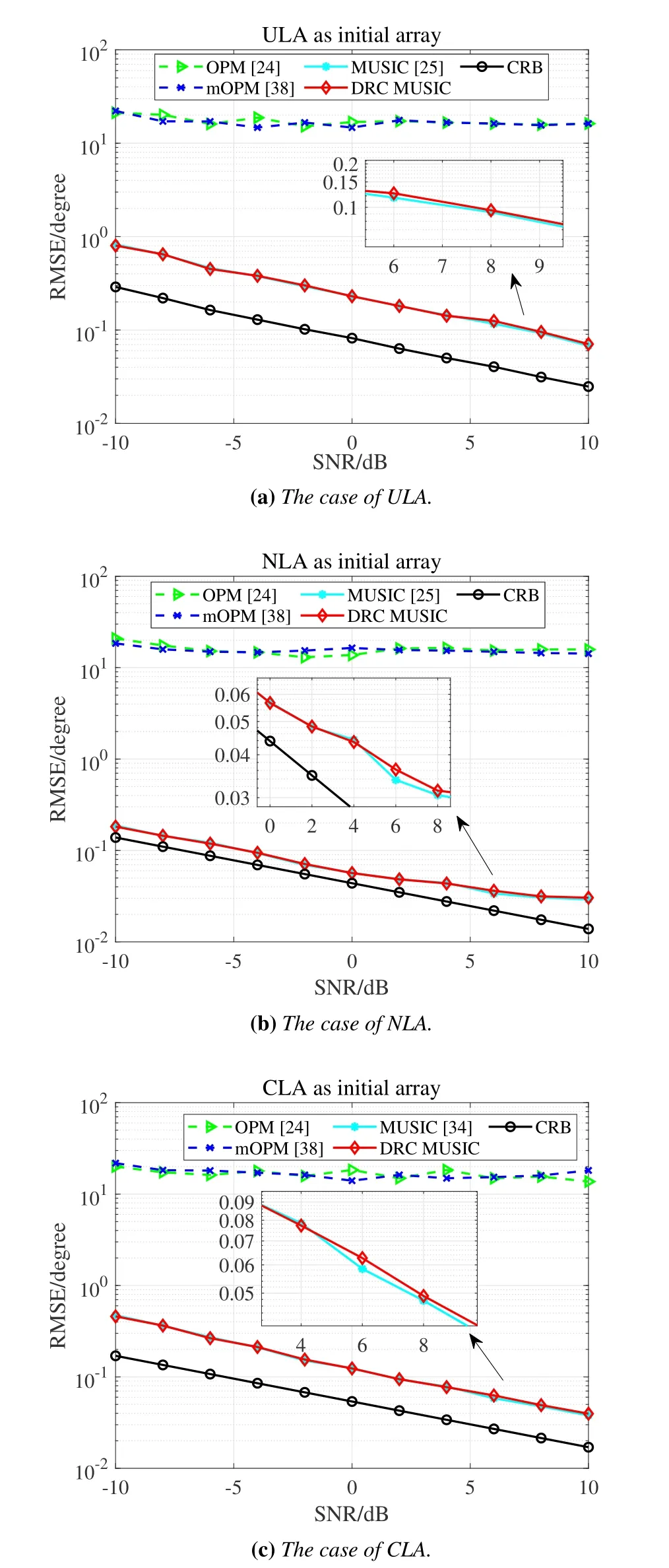
Figure 7. RMSE versus SNR for different initial arrays(F=2048).
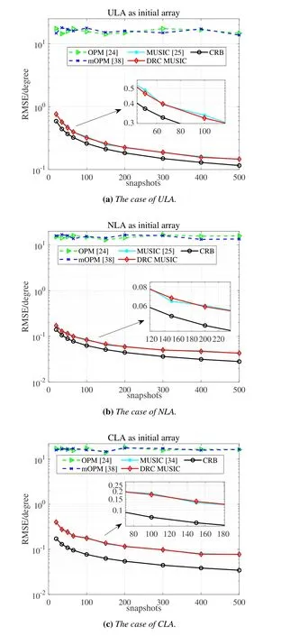
Figure 8. RMSE versus the number of snapshots for different initial arrays(SNR=10 dB).
5.3 Comparison of Computational Complexity
In this subsection,the algorithmic complexity of our proposed DRC MUSIC is discussed and the comparisons between different methods are also made to verify the superiority of low complexity of our method.
Generally,the complexity of the MUSIC algorithm mainly results from the covariance matrix calculation,EVD,and the spectral peak searching [10,32].Specifically,the complexity of the calculation of the covariance matrix is about,whereDrowis the number of the covariance matrix rows.The major complexity of EVD is.As for the spectral peak searching,it mainly incorporates the spectral function calculation with the searching step Δμand Δγ.Thus,the complexity of the spectral peak searching is given as+Drow)).
To clearly present the complexity,we given the total complexity of different methods in Table 2.Also,the histograms,which show the relationship between the complexity and the number of sensors,are given in Figure 9 to further verify the good property of low complexity of our proposed DRC MUSIC.As for the cases of ULA and NLA,the number of sensors is selected asM=6,M=8,M=10,andM=12.While under the case of CLA,the number of sensors of subarray2 is fixed atM2,cla=5,and that of subarray1 ranges from 4 to 10 with step 2.Accordingly,the parameter TCP is also given with the sensors number on the basis of the analysis in Section III.Also,the number of snapshots isF=2048.Besides the above specified parameters,the other keeps unchanged.As the figures indicated,our proposed DRC MUSIC algorithm can yield the remarkable decrease in respect of computational complexity by utilizing the decoupling process and transforming the 2D spectral peak searching into 1D searching.Compared with the 2D searching,since the EVD has a small proportion in the overall complexity,the OPM[27]and mOPM[41]methods still encounter high complexity.
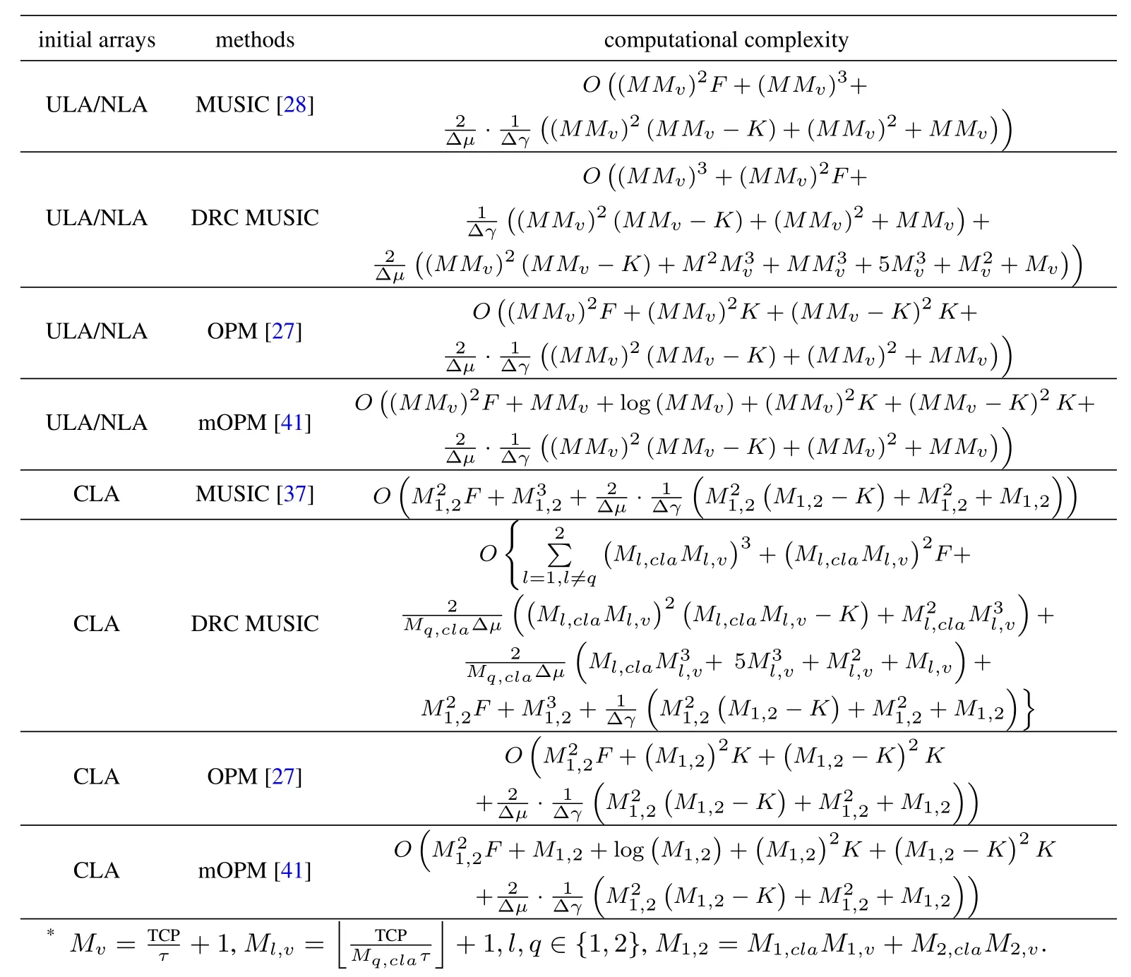
Table 2. Computational complexity of different methods.
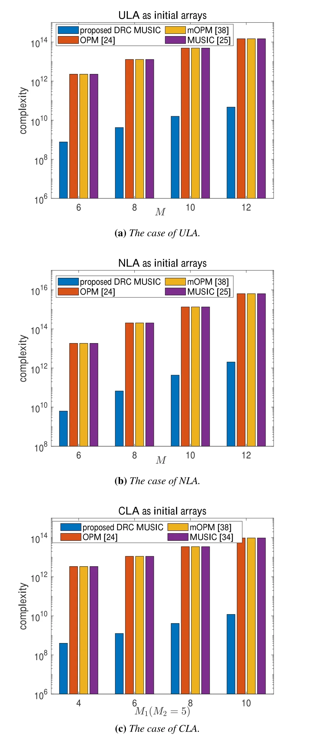
Figure 9. Comparison of computational complexity with the number of the physical sensors.
5.4 Simulation Results on Motion Direction
To further study the impact of the offset angleαon the performance,we fix the simulation parameters at SNR=10 dB andF=2048.The parameterαvaries from 0°to 180°with step Δα=10°due to the symmetry.Other parameters are the same as the simulations in subsection 5.2.Figure 10 presents the RMSE and CRB with the differentα.Notably,the virtual array aperture realizes the largest and the performance achieves optimal case when the offset angleαis about 90°,which is consistent with our analyzation in subsection 2.2.Moreover,our proposed DRC method is more robust than the OPM and mOPM,whose estimated noise subspaces still have a large gap from the true noise subspaces when the motion directionαis far away from 90°.Additionally,since the simulation is conducted with the settings (SNR=10 dB,F=2048) and the effective aperture resulting from the virtual uniform arrays in ULA and NLA is large,the effect of noise in the OPM is reduced.Then the OPM and mOPM achieve nearly the same performance in the cases of ULA and NLA.
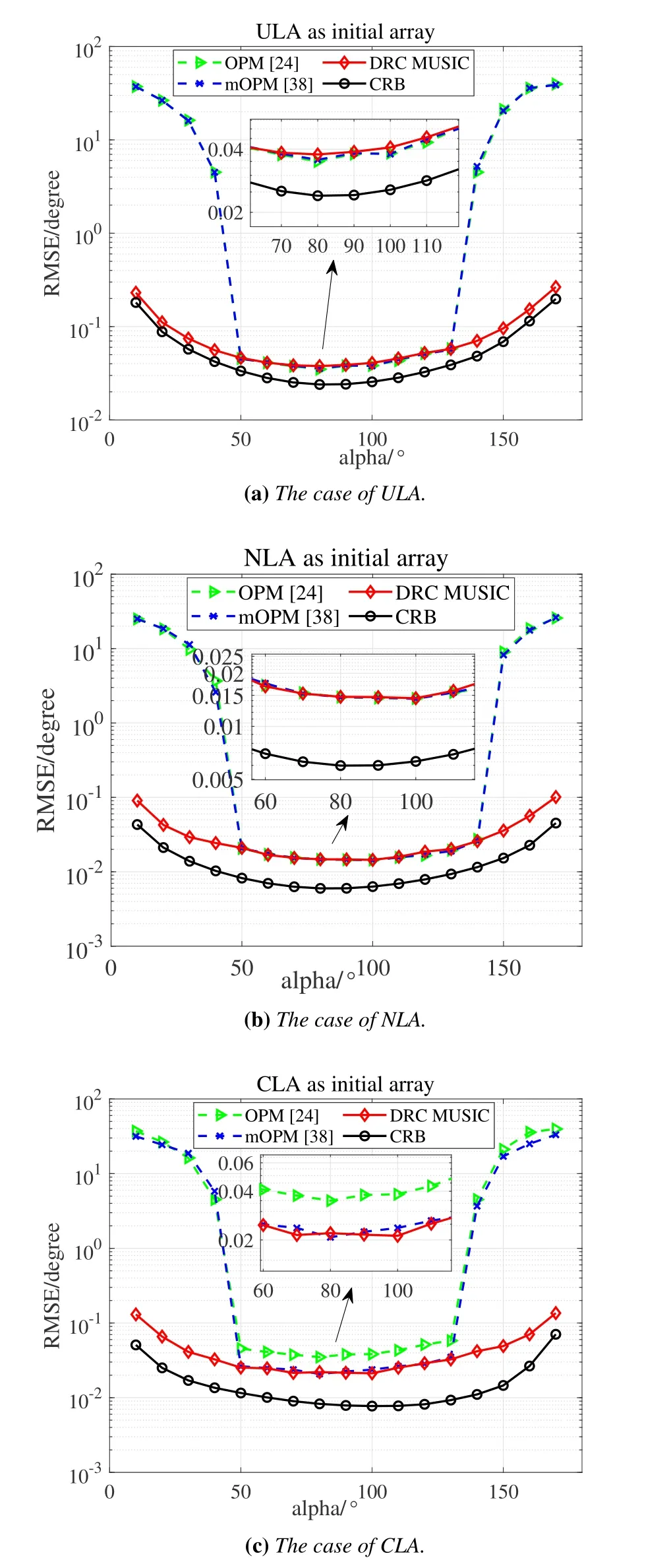
Figure 10. RMSE versus the offset angle α(SNR=10 dB,F=2048).
On the basis of the above simulations,it is obvious that our proposed DRC MUSIC not only keeps the superiority of high estimation accuracy,but also greatly reduces the computational complexity and gains better universality in our motion scheme,which can make the scheme further conform to the practical scenes.
VI.CONCLUSION
In this paper,a novel scheme of 2D DOA estimation is proposed to realize the good property of high accuracy and reduce the complexity by exploring the linear arrays motion.The linear arrays located atx-axis move along an arbitrary direction at a constant velocity and snap per fixed time delay.All the received signals at different time are synthetically processed to enlarge the virtual array aperture and achieve underdetermined 2D DOA estimation.Moreover,an algorithm named DRC MUSIC with high accuracy and low complexity as well as better universality is proposed in this paper.The simulation results further verify the good properties of our proposed scheme.
ACKNOWLEDGEMENT
This work was supported in part by the Key R&D Program of Shandong Province,China(No.2020CXGC010109) and in part by the Beijing Municipal Science and Technology Project(Z181100003218015).
杂志排行
China Communications的其它文章
- Secure and Trusted Interoperability Scheme of Heterogeneous Blockchains Platform in IoT Networks
- Intelligent Edge Network Routing Architecture with Blockchain for the IoT
- Privacy-Preserving Deep Learning on Big Data in Cloud
- PowerDetector: Malicious PowerShell Script Family Classification Based on Multi-Modal Semantic Fusion and Deep Learning
- Dynamic Task Offloading for Digital Twin-Empowered Mobile Edge Computing via Deep Reinforcement Learning
- Resource Trading and Miner Competition in Wireless Blockchain Networks with Edge Computing
