Silicon photomultiplier based scintillator thermal neutron detector for China Spallation Neutron Source(CSNS)
2023-10-11XiuPingYue岳秀萍ZhiFuZhu朱志甫BinTang唐彬ChangHuang黄畅QianYu于潜ShaoJiaChen陈少佳XiuKuWang王修库HongXu许虹ShiHuiZhou周诗慧XiaoJieCai蔡小杰HaoYang杨浩ZhiYongWan万志勇ZhiJiaSun孙志嘉andYunTaoLiu刘云涛
Xiu-Ping Yue(岳秀萍), Zhi-Fu Zhu(朱志甫), Bin Tang(唐彬), Chang Huang(黄畅), Qian Yu(于潜),Shao-Jia Chen(陈少佳), Xiu-Ku Wang(王修库), Hong Xu(许虹), Shi-Hui Zhou(周诗慧),Xiao-Jie Cai(蔡小杰), Hao Yang(杨浩), Zhi-Yong Wan(万志勇),Zhi-Jia Sun(孙志嘉), and Yun-Tao Liu(刘云涛)
1Engineering Research Center of Nuclear Technology Application,East China University of Technology,Ministry of Education,Nanchang 330013,China
2Spallation Neutron Source Science Center,Dongguan 523803,China
3Zhengzhou University of Technology,Zhengzhou 450044,China
4Institute of High Energy Physics,Chinese Academy of Sciences,Beijing 100049,China
5Lanzhou University,Lanzhou 730000,China
6Institute of Modern Physics,Chinese Academy of Sciences,Lanzhou 730000,China
7Zhengzhou University,Zhengzhou 450001,China
8Southwest University of Science and Technology,Mianyang 621002,China
Keywords: neutron detector, silicon photomultipliers (SiPMs), 6LiF/ZnS(Ag), China Spallation Neutron Source(CSNS)
1.Introduction
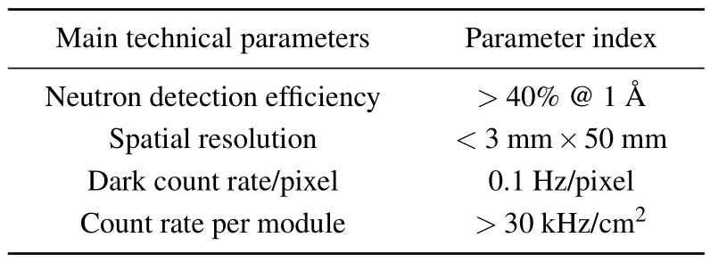
Neutron scattering technology has been widely used in condensed matter physics, chemistry, life sciences, materials science, and other fields as an ideal probe for studying the structural and dynamic properties of matter.[1,2]The Chinese Spallation Neutron Source (CSNS) successfully produced its first neutron beam on August 28, 2017.It has been running steadily since March,2018.[3]According to the construction plan of neutron instruments, the energy-resolved imaging spectrometer (ERNI) will be installed in 2022.ERNI is a combined facility of neutron imaging and neutron diffraction that can provide strong penetration, high resolution, andin-situlossless imaging characterization.The instrument can be used to characterize and analyze the internal microstructure,defects,morphology,and stress of a device,as well as for online studies of the internal dynamic processes of materials and devices.In addition, it can also provide key data support for the simulation and modeling of practical applications and running systems,and time-of-flight(TOF)techniques can be used by ERNI for energy-selective imaging applications.The ERNI is based on Bragg-edge imaging,supplemented by conventional neutron imaging and neutron diffraction, with a neutron diffraction sensitivity area of larger than 4 m2and a sample-to-detector distance of 2 m.According to the physical design of the ERNI, the performance of the neutron detector must fulfill the parameters listed in Table 1.

Table 1.Main parameters of the detector modules for ERNI.
Owing to its high detection efficiency and steady performance, the3He tube is widely used in various neutron spectrometers.However, because of the shortage of3He gas, and consequently its high price,there is an urgent need to develop other types of neutron detectors to replace the3He tubes.[4,5]Scintillator neutron detectors have gradually replaced3He tubes in many neutron instruments because of their unique advantages including high detection efficiency, fast time response, goodn/γdiscrimination, and ease of fabrication in large areas, such as that of IMAT (ISIS),[6]TAKUMI (JPARC),[7]POWGEN(SNS),[8]and EMD(CSNS).
Many scintillator detectors used in neutron spectrometers utilize multi-anode photomultiplier tubes(MA-PMT)for photoelectric conversion.And the signals from the PMT are processed by traditional discrete readout electronics with large volume and high power consumption.[9,10]The main detector of the general purpose powder diffractometer (GPPD) in CSNS is the self-developed large-area scintillation detector array with a position resolution of 4 mm×4 mm and a thermal neutron detection efficiency of more than 45%@2 ˚A.[11]All indicators fulfill the requirements of the spectrometer.But this large-area scintillator detector array has poor detection efficiency uniformity.[3]Although the MA-PMT has stable performance and high gain, it has some problems, such as poor uniformity of the gain between each working unit,high working voltage, large volume, and poor resistance to magnetic field interference.In recent years, SiPMs have attracted increasing attention owing to their high single-photon resolution, ease of integration, and low operating voltage.[12–14]In this work, to achieve excellent detector performance such as low cost, small dead area, and good uniformity of detection efficiency,the SiPM is used instead of the MA-PMT for photoelectric conversion.A self-designed ASIC electronics has also been developed for the new detector system.
In this study, we developed a detector prototype with a neutron sensitive area of 50 mm×200 mm using SiPMs for photoelectronic conversion and using ASIC electronics for signal process and readout.The performances of the detector,such as dark count rate, detection efficiency, position resolution, and maximum count rate, were tested in neutron beam 20#at the CSNS.
2.Detector prototype structure
2.1.Detector working principle
6LiF/ZnS(Ag)is a commonly used neutron sensitive scintillator screen.The incident neutrons react with neutronsensitive materials6Li in the scintillation screen to produceαparticles and tritium nuclei.Secondary particles deposit energy and emit photons in the scintillation material.The ZnS scintillation material is a polycrystalline powder with a particle size of tens of microns, which has high luminous efficiency forαparticles,low sensitivity toγ,and a highn/γratio.According to our previous test of different6LiF/ZnS(Ag)screens and the manufacturer’s recommendation,[15]scintillator screens with the following characteristics are chosen: the ratio of the masses of6LiF to ZnS(Ag)is 1:2, and the screen thickness sets to 400 μm.[16,17]The luminescence spectrum is 400 nm–600 nm with its peak at 412 nm.Using transverse or longitudinal arrangements of light collecting fibers to reduce the number of readout electronics channels for the pixel type detector is a common practice for position-sensitive detector.The wavelength-shifting fiber (WLSF) array is designed here to reduce the number of readout electronics channels from tens of thousands down to a few hundred for 3 mm pixel size.Through the research of the detectors for the GPPD,the WLSF from kuraray with 1 mm diameter(Y-11(200)MS)is still suitable.[11,18]Considering that each end of two 1 mmdiameter WLSFs needs to be coupled to the SiPM entrance window,the effective working area of the SiPM device needs to be about 3 mm×3 mm.The MicroFC-30035 SiPM from Sensl is adopted.[19]
After amplification,filtering,and shaping by the readout electronics,the optical signal detected by the SiPM is fed into the data acquisition system based on a field programmable gate array (FPGA).The data are analyzed by online and offline programs to obtain the position and time information of the incident neutrons.
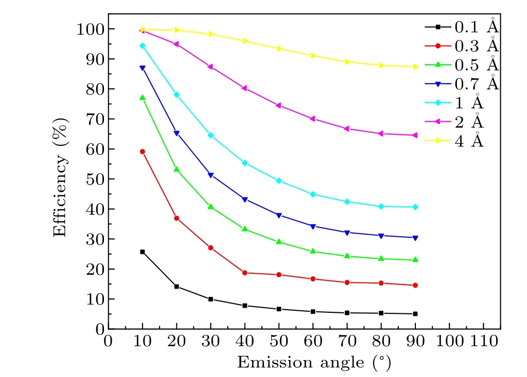
The detection efficiency of the scintillation screen depends on the energy deposition and photon emission probability of the neutrons in the scintillation screen.Because of the opaque of the6LiF/ZnS screen, the scintillator screens are designed to tilt to increase the path of incidence neutrons without increasing the emission path of the scintillating photons.This could improve the detection efficiency effectively.The simulation results are shown in Fig.1 by GEANT4 for different tilt angles of the6LiF/ZnS screen.With a decrease in the angle between the scintillation screen and the incident neutron, the detection efficiency of the scintillation screen gradually increases.At an incidence angle of 20°, the nuclear reaction conversion efficiency of the 400 μm thickness6LiF/ZnS screen can reach 78%at the neutron wavelength of 1 ˚A.Therefore,we change the traditional vertical neutron incidence structure and design the detector as a tilt incidence structure.According to the physical design of ERNI,the sensitive area of the detector is 200 mm×50 mm, and the sensitive area will be equipped with 64 inclined6LiF/ZnS (Ag)scintillation screens.Considering the limits of the mechanical design when optimizing neutron absorption efficiency, minimum dead area and maximum light collection and the space needed for two 1 mm diameter WLSFs arrangement in each pixel, the tilt angle of the detector scintillation screen is determined to be 17°.This structure defines the 3 mm×50 mm pixel size and 64 pixel channels.A schematic design of the detector head part is shown in Fig.2.

Fig.1.Neutron conversion efficiency of scintillation screens at various tilt angles at different wavelengths.

Fig.2.Schematic design of the detector head part for the traditional vertical neutron incidence structure(left)and the tilt incidence structure(right).
2.2.Detector prototype
The detector prototype is a one-dimensional detector with the striped pixels (3 mm×5 mm).Two longitudinally distributed 1 mm-diameter WLSFs are placed on the surface of the scintillation screen to absorb the photons emitted by the scintillation screen in each pixel.In addition, each pixel is optically isolated by an aluminum film to prevent optical crosstalk between adjacent channels.And the four end faces of the two optical fibers are coupled to the sensitive surface of the SiPM by a specially designed couple base.The detector prototype has 64 pixels and 128 WLSFs.The structural diagram of the detector is shown in Fig.3.

Fig.3.Design of the detector structure.
The detector prototype picture is shown in Fig.4.The detector has 64 electronic channels, and two 32-array SiPMs with a unit sensitive area of 3 mm×3 mm are used for the photoelectric signal conversion.We have designed a fixture for coupling optical fiber with the SiPM.The couple base of the WLSFs and SiPMs has 32 holes with a diameter of 3 mm.After grinding, the two optical fibers of each pixel of the detector will be placed in the small hole of the fixture in order.Four fiber ends in each hole are directly coupled to the SiPM array.

Fig.4.Detector prototype picture.
3.ASIC electronics
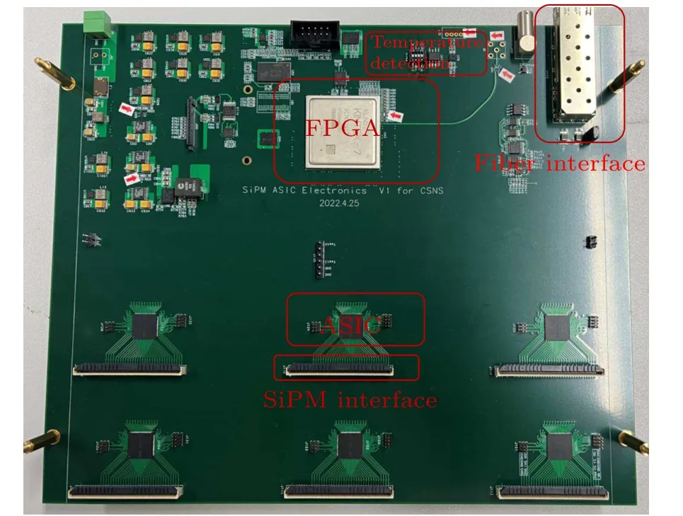
The electronic system of the detector collects the weak electrical signal output from the SiPMs, discriminates, amplifies, reshapes, and performs analog-to-digital conversion,data compression, and packaging.Finally, the neutron event data are transformed to the computer for analysis and calculation.The data acquisition system is divided into preamplification and data acquisition circuit systems.Figure 5 shows the block diagram of the electronics.The preamplifier circuit system includes an IHEP SiPM ASIC chip,circuit protection,power management,chip address configuration,DAC configuration,DAC scale,signal detection rectification,internal clock configuration modules, and an adaptation network.The ASIC chip is used to amplify, shape, filter, and discriminate the analog signal.The DAC configuration module can adjust the threshold value of the discriminator and also adjust the width limit value of the filter to reduce the dark noise from the SiPMs.The preamp circuit converts the analog signal to a digital signal and sends it to the data-acquisition system.The data acquisition system is primarily controlled by an FPGA.The FPGA controls the charge measurement,temperature sensing,analog-to-digital conversion,and finally uploads the data packet to the computer.Figure 6 shows the picture of the readout electronics board.
Radiation source tests of the detector system in the laboratory were carried out to verify the performance of the readout electronics.A241Am alpha source was positioned on one pixel of the detector.The signal out from electronics was monitored by an oscilloscope.The test results are shown in Fig.7.After the pre-amplification circuit,the signal was quite smooth, which aided in the subsequent identification of the signals and noise.The width of the signal pulse was less than 3 μs and its rising time was less than 200 ns.It is quite easy to distinguish from the noise of the SiPM.

Fig.5.Electronics block diagram.

Fig.6.The picture of the readout electronics board.

Fig.7.Oscilloscope observed alpha signal.
4.Performance of the detector prototype
4.1.Noise of the detector
Most of the noise in the detector system comes from the SiPMs.Because the SiPM is a semiconductor-based photoelectric conversion device, it is very sensitive to temperature changes.In future engineering applications of the detector,the detector will work in a light-avoid space.The heat dissipation of the electronics board changes the space temperature.These changes will affect the performance of the SiPM,such as the gain and the dark count rate.With the increase of the temperature,the phonon vibration increases in the SiPM.The kinetic energy loss of avalanche carriers increases due to the increase in scattering collision,and the gain of the SiPM decreases with the increase in temperature.In contrast,the dark count rate of the SiPM increases with the increase of temperature.Because of the semiconductor characteristics, the carriers increase at higher temperatures.
The change in the performance of the SiPMs will directly lead to the inaccuracy and unreliability of the neutron test.The curve of gain versus temperature and the curve of gain versus voltage of the SiPM were measured, which showed to guide the design of temperature drift compensation module.The temperature compensation coefficient of the SiPM was calculated to be 21.3 mV/°C, which is the same as the factory instruction.Using the temperature compensation coefficient,we developed an FPGA-based temperature compensation module.The working temperature of the SiPM was measured in real time using a temperature sensor welded on the SiPM and then fed back to the FPGA on the electronic board.The gain can be compensated by adjusting the working voltage of the SiPMs.

Fig.8.SiPM noise counting at different temperatures.
With the action of a temperature compensation module,we tested the noise count rate of the detector prototype at different temperatures, as shown in Fig.8.Although the gain of the SiPMs was stable, the dark noise counts still increase when the temperature rose.The dark noise counts were below 0.5 s-1·pixel-1in the temperature ranging from 20°C to 30°C,which means the working environment temperature should be maintained below 30°C.A cooling fan was installed in the light-avoid area to keep the temperature of the SiPM between 26°C–28°C.
4.2.Detection efficiency
A3He counting tube(20 atm)is used as the primary comparison tool for testing the detection efficiency of the detector.The neutron detection efficiency of the detector to be tested at different neutron wavelengths can be obtained by normalizing the counting of the detector prototype with that of the3He tube.The detection efficiency of the detector prototype can be calculated by
whereNSDandN3Heare the total counts for the scintillator detector and standard3He tube neutrons,respectively.η3Heis the detection efficiency of a standard3He tube.Figure 9 shows a block diagram of the testing principle.Because the neutron wavelength distribution of BL20 is wide, a mica (0010)(008) monochromator is used to extract neutrons at specific wavelengths and reduce the neutron intensity.When the angle between the mica monochromator and the neutron beam is 45°,the neutrons of a specific wavelength can be extracted.A standard3He tube (252315, LND) with a pressure of 20 atm and a diameter of 1 inch is used to measure the incident neutron intensity from a shielded slit with a width of 1 mm.The standard3He tube is then removed, and the neutron intensity is measured using a prototype detector under the same conditions.
Figure 10 shows the TOF spectra of the3He tube and the detector prototype.It can be clearly observed that the flight time interval of the characteristic peaks at different wavelengths in the TOF spectra of both the3He tube and the detector correspond to each other.The TOF-to-neutron wavelength conversion can be obtained from
whereLandtare the distance of the detector from the center of the target station and the TOF time,respectively.The inset of Fig.10 shows the characteristic peaks of the3He tube and the detector at a neutron wavelength of 2.87 ˚A.From Fig.10,we can observe that the characteristic peak of the detector is shifted to the right relative to that of the3He tube.As shown in Fig.9, the detector prototype is located behind the3He tube.So the distance from the center of the target station to the scintillator detector is longer.According to Eq.(2),under the same neutron wavelength, the distance is proportional to the time.Based on the difference in the peak value, we calculate that the distance between the3He tube and detector is 3 cm,which is consistent with the actual distance.In addition, it can be observed in the illustration that the pulse width of the characteristic peak of the3He tube is larger than that of the detector.This is because the diameter of the standard3He tube we adopted is 1 inch(25 mm),so the flight distance migration of neutrons in the3He tube is greater than that of neutrons in the scintillator detector (10 mm).Therefore, we can say that the wavelength resolution of the scintillator detector is higher than that of the3He tube.

Fig.9.Schematic of the detection efficiency test principle.

Fig.10.TOF spectrum of the 3He counter and detector.The inset shows the characteristic peak of the 3He tube and detector when the neutron wavelength is 2.87 ˚A.
We tested the detection efficiency at three different positions in the sensitive area of the detector prototype.The detection efficiency of the3He tube reached 100% at 2.87 ˚A wavelength and 99.8% at 1.59 ˚A.The detection efficiencies of three pixels of the scintillator detector at different neutron wavelengths were calculated, as shown in Fig.11.The highest detection efficiencies of the pixel are 63.3%at 1.59 ˚A and 68%at 2.39 ˚A.The detection efficiencies of each pixel are not exactly the same.This is caused by the small difference in the process of making the detector.There are some differences in each WLSF and in the flatness of each scintillator screen.The coupling between the WLSF and the SiPM is also slightly different.By simple nonlinear fitting, the detection efficiencies of the three pixels are found to be all higher than 40%at 1 ˚A,which fulfill the requirements of the ERNI.In the following work, we will measure and optimize the detection efficiency and non-uniformity of the detector.By adjusting the readout electron threshold of each pixel, the neutron counting uniformity of each pixel is optimized to more than 90%.On this basis, the non-uniformity of detection efficiency has little influence on the stress test results of the sample.

Fig.11.Detection efficiencies of different pixels at different neutron wavelengths.
4.3.Max count rate
The neutron signal measured by the scintillator detector based on ZnS/6LiF has long optical attenuation,and the pulse width of the signal is generally approximately 10 μs with slow luminescent component.The application of this type of scintillator detector is limited by its low count rate.Through the optimization by the self-designed readout electronics,the slow component of the neutron signal larger than 2 μs is eliminated.We tested the max count rate of the detector by adjusting the slit length which was placed in the neutron exit hole to control the neutron flux.The detector was placed in the straight direction of the beam line, and a boron-containing aluminum plate with different slit lengths were placed in front of the detector.The counting rate curve can be obtained when the slits changed,as shown in Fig.12.The counting rate of the detector increased linearly with increasing slit length.When the slit length larger than 20 mm,the counting rate of the detector increased in nonlinearity.When the slit length was greater than 80 mm, the counting rate reached 459 kHz which is nearly saturation.Through linearly fitting of the counting-rate vs.slit length,we obtained that the highest linear counting rate is about 247 kHz when the slit length is 20 mm.

Fig.12.Counting rate test results.The inset shows the counting rate increases linearly with the slit length when the slit length is less than 20 mm.
4.4.Spatial resolution
According to the requirements of ERNI,the pixel size of the detector prototype was designed to be 3 mm×50 mm.A boron–aluminum plate with 1 mm wide slit was used to test the spatial resolution of the detector.The position resolution test results for the detector are shown in Fig.13.It can be seen that one irradiated peak is clearly resolved.The small neutron counts in the adjacent pixels were caused by the poor neutron collimation.Since each pixel is optically isolated,the spatial resolution corresponds to the detector pixel size.The minimum spatial resolution of the detector in the horizontal direction is 3 mm.

Fig.13.Results of position resolution test.
5.Preliminary engineering design of the detector for ERNI application
Figure 14 shows the picture of two kinds of detector units which contains six and four small detector modules respectively.These units will be fixed on a mechanical support frame to form an arc structure with a radius of 2 m.All the units will be placed in the shell of a boron-containing aluminum plate to protect from light and neutron radiation.Each detector module in the unit consists of 64 pixels with a size of 3 mm×50 mm.All detector units are mounted on a bank bracket according to the laser positioning data.

Fig.14.Preliminary engineering design of the detector for ERNI.
6.Conclusion
We developed a scintillator neutron detector prototype for the ERNI based on a6LiF/ZnS (Ag) scintillation screen and SiPM array.The neutron signal was processed by a selfdesigned electronics based on the ASIC chip and FPGA.The prototype of the detector was tested in neutron beam 20#of the CSNS.The test results showed that the position resolution of the detector was 3 mm,the max count rate was 247 kHz,and the detection efficiency was greater than 40% at 1 ˚A neutron wavelength.The test results showed that the detector fulfilled the requirements of the ERNI.This detector prototype could be a good working unit for the array splicing structure for the ERNI.We will start the mass production of the nearly 400 detector units for future installation in the ERNI.AcknowledgmentsProject supported by the National Natural Science Foundation of China(Grant Nos.11875273,U1832111,61964001,and 12275049), the Science Foundation of Guangdong Province of China (Grant No.2020B1515120025), the Neutron Physics Laboratory Funding of China Academy of Engineering Physics (Grant No.2018BC03), the General Project of Jiangxi Province Key Research and Development Program (Grant No.20212BBG73012), the Key Scientific Research Projects of Henan Higher Education Institutions(Grant Nos.23A490002 and 24A490001), and the Engineering Research Center of Nuclear Technology Application (Grant No.HJSJYB2021-4).
猜你喜欢
杂志排行
Chinese Physics B的其它文章
- Robustness of community networks against cascading failures with heterogeneous redistribution strategies
- Identifying multiple influential spreaders in complex networks based on spectral graph theory
- Self-similarity of complex networks under centrality-based node removal strategy
- Percolation transitions in edge-coupled interdependent networks with directed dependency links
- Important edge identification in complex networks based on local and global features
- Free running period affected by network structures of suprachiasmatic nucleus neurons exposed to constant light
