Effect of sharp vacuum–plasma boundary on the electron injection and acceleration in a few-cycle laser driven wakefield
2023-10-11GuoBoZhang张国博SongLiu刘松DeBinZou邹德滨YeCui崔野JianPengLiu刘建鹏XiaoHuYang杨晓虎YanYunMa马燕云andFuQiuShao邵福球
Guo-Bo Zhang(张国博), Song Liu(刘松), De-Bin Zou(邹德滨), Ye Cui(崔野),Jian-Peng Liu(刘建鹏), Xiao-Hu Yang(杨晓虎),3,‡, Yan-Yun Ma(马燕云), and Fu-Qiu Shao(邵福球)
1Department of Nuclear Science and Technology,National University of Defense Technology(NUDT),Changsha 410073,China
2Department of Physics,National University of Defense Technology,Changsha 410073,China
3Collaborative Innovation Center of IFSA(CICIFSA),Shanghai Jiao Tong University,Shanghai 200240,China
4College of Advanced Interdisciplinary Studies,National University of Defense Technology,Changsha 410073,China
Keywords: laser wakefield acceleration,few-cycle laser,sharp vacuum–plasma boundary
1.Introduction
Electron beams with tens of MeV energies are important tools to explore the properties and internal structures of matter,and have important and extensive practical applications in industry,science,and technology.[1]Traditional radio-frequency(RF) electron accelerators are not only large and expensive,but also their main purpose is to carry out advanced physical research, which limits them to primarily serving basic research and advanced technology.In recent years, due to the tremendous acceleration gradient (more than 100 GV/m), a table-top electron source from a laser wakefield accelerator has shown great potential to be the next generation of compact accelerator.[2–8]In laser wakefield acceleration (LWFA), the ponderomotive force of an ultra-short ultra-intense laser pulse can radially expel plasma electrons,which leads to the formation of so-called“bubble”regime.A large number of electrons can be self-injected into the bubble and accelerated to high energy, which can be used for the generation of positron,[9]betatron radiation,[10–13]and free electron laser.[14,15]In recent LWFA experiments, the electron beam with a maximum energy of 8 GeV and an energy spread of 0.3% have been demonstrated.[16,17]Currently, the development of laser technology makes it possible to obtain few-cycle laser pulse with high-repetition-rate experimentally.[18,19]Compared to a multi-cycle laser, the few-cycle laser has a larger frequency bandwidth, and ponderomotive force and carrier-envelopephase (CEP) effects jointly dominate electron injection and acceleration.Recently,many works have been reported to investigate the LWFA driven by the few-cycle laser pulses,and the electron beams with pulse width of femtosecond or attosecond and energy of tens of MeV can be obtained.[20–27]Effective electron injection schemes are required for applications of electron beam.Multiple electron injection methods have been developed, such as self-injection,[28]density gradient injection[29,30]and ionization injection,[31,32]and other mechanisms.[33–35]In addition, the BII induced by sharp vacuum–plasma boundary is also a practical and effective injection method.[36]The BII driven by a few-cycle laser is different from the usual LWFA, which contains new physical processes and the electron beam parameters show different properties.Therefore,the electron injection and acceleration driven by a few-cycle laser with a sharp vacuum–plasma boundary are worth further study.
In this paper, we investigate the effect of the sharp plasma–vacuum boundary on electron injection and acceleration in a few-cycle laser driven wakefield.It is found that when a few-cycle laser pulse enters the plasma with a sharp vacuum–plasma boundary, the isotropic BII occurs first, and then the periodic SI is caused by CEP shift.Three-dimensional particle-in-cell simulations show that the injected electron beam parameters are determined by the coupling of BII and SI,and the electron charge of the BII only accounts for a small part of total charge.The electron beam parameters can be controlled by tuning the laser intensity and plasma density.
2.Simulation model and results
In order to study the effect of sharp vacuum–plasma boundary,a series of 3D particle-in-cell(PIC)simulations are carried out with the LAPINE code.[37,38]A linearly polarized few-cycle laser with polarization along theydirection and a wavelength ofλ0=0.8 μm propagates along thezdirection.The normalized electric field of the few-cycle laser is given by

Figure 1 shows the evolution of the electron density transverse slice distributions.When a few-cycle laser enters the plasma, the electrons pulled out by the ponderomotive force can undergo BII due to the sharp vacuum–plasma boundary,as shown in Figs.1(a)and 1(b).After that, the bubble shows asymmetry in the laser-polarized plane because of the rapidly shift of CEP,and periodic self-injection controlled by the CEP occurs simultaneously.It is worth noting that the bubble is still symmetric in the plane transverse to the laser non-polarization direction.The corresponding evolution of electron density aty=1 μm (black line) andy=-1 μm (red line) is shown in Figs.1(c),1(f)and 1(i).One can see that the CEP of the laser pulse shift rapidly due to the high plasma density,and the local electron density at the symmetric position of the laser electric field shows the difference in value and distribution,which leads to the different plasma wavelengths at the symmetric position of the bubble.The peak electron density is 0.32ncaty=1 μm,while it is only 0.26ncaty=-1 μm,as shown in Fig.1(c).The local electron density in the laser polarization direction changes the direction of laser electric fields maximum value periodically, and the period is the same as that of CEP shift.
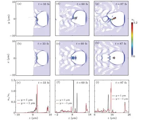
Fig.1.The evolution of the electron density transverse slice distributions including the laser polarized plane y–z and the laser non-polarized plane x–z at t =33 fs[(a)and(b)],t =60 fs[(d)and(e)],and t =87 fs[(g)and(h)].The corresponding electron density at y=1 μm(black line)and y=-1 μm(red line)[(c),(f),and(i)].
In order to describe the correspondence between CEP shift and bubble evolution in detail, the evolution of the onaxis laser electric field,the on-axis electron density,the maximum laser electric field (red line), and the absolute value of the minimum laser electric field(blue line),and the difference in plasma wavelength between two symmetric positions are shown in Fig.2.Due to the effect of plasma dispersion and Gouy phase shift,the CEP moves rapidly.In previous studies,a more precise phase shift is described as[21]
wherezR=is the Rayleigh length,neis the electron density, andnc=1.1×is the critical density.Therefore, we can theoretically calculate the distance of CEP shiftπas 6.2 μm, which is consistent with the simulation results (i.e., 6.5 μm).Figure 2(b) shows the evolution of the on-axis electron density distribution.One can see that the maximum local electron density at the position of the laser electric field also changes periodically, and BII occurs when the bubble is closed until it accelerates to the dephasing point.Meanwhile, the laser electric field increases first due to the self-focusing and then decreases due to the energy depletion and pulse dispersion,and the maximum electric field changes periodically,as shown in Fig.2(c).Figure 2(d)shows plasma wavelength difference ΔLbetween the positions ofy=1 μm andy=-1 μm.The wavelength difference also oscillates periodically,and the oscillation period is consistent with that of the CEP shift.

Fig.2.Evolution of the on-axis laser electric field (a), the on-axis electron density(b),the maximum laser electric field(red line)and the absolute value of the minimum laser electric field(blue line)(c),plasma wavelength difference ΔL between the positions y=1 μm and y=-1 μm(d).
Figure 3 shows thez–pzphase space distribution of the injected electrons beams at different time and the trajectories of the BII electrons.BII electrons are firstly accelerated att=40 fs, as shown in Fig.3(a).After that, the first and second SI occur att=60 fs andt=80 fs due to the periodic deformation of bubble, respectively.The electron beam injected in different ways separates in phase space and mixes in real space, and the BII electrons are mainly located at the high energy part.The phase space distribution of the electron beam at the dephasing point show that the BII and SI electron beam mix with each other in the energy space,and finally an electron beam with a relatively concentrated energy is obtained.Figure 3(e)shows the trajectories of some typical BII electrons,where the injection occurs rapidly during the sharp vacuum–plasma boundary, which is quite different from that of the periodic self-injection with few-cycle laser.

Fig.3.Distribution of the injected electrons(including BII and SI,γ >10)in the z–pz phase space at (a) t =40 fs, (b) t =60 fs, (c) t =80 fs, and(d)t=133 fs.(e)The trajectories of the BII electron beam.
The evolution of the electron charge(black line)and maximum electron density (red line) are shown in Fig.4(a), the condition of the calculated electron charge isγ >10, whereγis the relativistic factor.One can see that the electron charge gradually increases until it reaches saturation aroundt=100 fs, and the maximum charge is 1.12 nC.Since the BII only occurs at the vacuum plasma boundary, and the injected electron beam is spatially separated from the SI, we can calculate the charge of BII as 0.2 nC, which only accounts for 18% of the total charge.Meanwhile, the maximum electron density gradually increases first and then tends to be stable,reaching a maximum of 15nc.Figure 4(b)shows the electron energy spectrum distribution of the total (blue line) and BII (red and black lines) att=133 fs.Although the BII and SI occur simultaneously, an electron beam with a central energy of 30.8 MeV and an absolute energy spread of 6.3 MeV is finally produced due to the evolution of injected electrons,and the BII electron beam is modulated by the driven-laser electric field.In addition, the normalized transverse emittance of the electron beam can be calculated byεn=σnσpn/(mec2),[39]σnis the root-mean-square(rms)beam radius andσpn/(mec2) is the normalized rms transverse momentum along thendirection,forn=xandy.The simulation results show that the total beam emittances areεy=3.7 μm·rad andεx=3.2 μm·rad.For the electrons of the BII,the spectrum width is large,the transverse emittances at the initial time areεy=1.9 μm·rad andεx=1.8 μm·rad due to the isotropic BII.However,the transverse emittance of the laser polarized direction(εy=1.1 μm·rad)is larger than that of the non-polarized direction(εx=0.4 μm·rad)att=133 fs because the BII electrons are modulated by the laser electric field(not shown here).
The CEP is an important control parameter for the fewcycle laser, the quality parameters of the injected electron beam as a function of the CEP are shown in Fig.5.Figures 5(a)and 5(b)show the total electron beam and BII electron beam energy spectrum distributions with different CEP att=133 fs.When the CEP=45°, the electron beam energy spectrum structure changes into a platform type, while in other cases, there is a small difference between the peak energy and the energy spectrum structure.However, the energy spectrum of the BII electron beam is controlled by CEP,and the peak energy is different.We calculate both the total charge and the ratio of the BII electron charge to the total charge,as shown in Fig.5(c).When the CEP=135°,the minimum total charge is 1.08 nC,and CEP=0°or CEP=180°,the maximum total charge is 1.13 nC.In other cases,the total charge is about 1.1 nC.Meanwhile,the ratio of the BII charge to the total charge fluctuates periodically with the CEP, and the maximum and minimum ratio are 21% and 16%, respectively, that is, the BII charge accounts for only about a fifth of the total charge.In addition,the transverse momentum and transverse emittance in the laser polarization direction can be controlled by the CEP.However, since most of the electrons are self-injected periodically, the transverse momentum and emittance in the laser non-polarized direction are small and do not evolve with the CEP.

Fig.4.(a)The evolution of the electron charge(black line)and maximum electron density (red line).(b) The total (blue line) and BII (red and black lines)electron energy spectrum distribution at t=133 fs.

Fig.5.(a)The total electrons and(b)BII electrons energy spectrum distributions with different CEP at t=133 fs.Total charge and the ratio of BII charge to the total charge(c),the transverse momentums and emittances(d)as a function of CEP.
In order to investigate the effects of laser intensity and electron density on the charge of the BII and SI,the evolution of the total charge and the ratio of the BII charge to the total charge with the laser intensity and electron density are shown in Fig.6.One can see that the total charge increases almost linearly with the increase of laser intensity,while the ratio of the BII charge to the total charge increases gradually and tends to saturation due to the increase of the BII charge,and the maximum ratio is only 19%,as shown in Fig.6(a).The total charge and ratio also increase with the increase of plasma density,the maximum ratio can up to 29%.In addition, one can see that isotropic BII and periodic SI always occur simultaneously under the simulation parameters.

Fig.6.The total charge and the ratio BII charge to the total charge as a function of the laser intensity (a) and electron density (b).The relativistic factor of the electron beam considered is γ >10.
3.Conclusion
In summary, we have investigated the effect of the sharp plasma–vacuum boundary on the electron injection and acceleration in a few-cycle laser driven wakefield.3D-PIC simulations show that the wakefield driven by a few-cycle laser first has an isotropic BII,and then the plasma bubble oscillates transversely and the electrons are injected periodically into the bubble due to the change of the local electron density at the symmetric position of the laser electric field.The BII,which occurs only once, accounts for a small part of the total injection,and an electron beam with a central energy of 30.8 MeV and charge of 1.12 nC can be obtained.The CEP can effectively tune the electron spectrum and the ratio of BII charge to the total charge,and one can further control the charge and ratio by optimizing the laser intensity and plasma density.The results are beneficial to electron acceleration and its applications,such as betatron radiation source.It is worth noting that a sharp vacuum–plasma boundary is used in the study,which is difficult to achieve such density profile experimentally.To illustrate the effect of scalelength in the front of plasma, we also simulation the BII by using a 5-μm linear-up ramp length(less than the plasma wavelengthλp).The simulation result is consistent with the sharp vacuum–plasma boundary condition(not shown here).In addition, it is possible to achieve such a density transition by selecting suitable knife edge to form shock wave in gas in future.[40,41]
Acknowledgements
Project supported by the National Natural Science Foundation of China (Grant Nos.12005297, 12175309,12175310, 11975308, and 12275356), the Strategic Priority Research Program of the Chinese Academy of Sciences(Grant No.XDA25050200), the Research Project of NUDT (Grant No.ZK21-12), and the Key Laboratory Foundation of Laser Plasma of Ministry of Education.De-Bin Zou also acknowledges the financial support from the NUDT Young Innovator Awards (Grant No.20190102) and Outstanding Young Talents.
猜你喜欢
杂志排行

Chinese Physics B的其它文章
- Dynamic responses of an energy harvesting system based on piezoelectric and electromagnetic mechanisms under colored noise
- Intervention against information diffusion in static and temporal coupling networks
- Turing pattern selection for a plant–wrack model with cross-diffusion
- Quantum correlation enhanced bound of the information exclusion principle
- Floquet dynamical quantum phase transitions in transverse XY spin chains under periodic kickings
- Generalized uncertainty principle from long-range kernel effects:The case of the Hawking black hole temperature