Bifurcations for counterintuitive post-inhibitory rebound spike related to absence epilepsy and Parkinson disease
2023-10-11XianJunWang王宪军HuaGuangGu古华光YanBingJia贾雁兵BoLu陆博andHuiZhou周辉
Xian-Jun Wang(王宪军), Hua-Guang Gu(古华光), Yan-Bing Jia(贾雁兵),Bo Lu(陆博), and Hui Zhou(周辉)
1School of Mathematics and Science,Henan Institute of Science and Technology,Xinxiang 453003,China
2School of Aerospace Engineering and Applied Mechanics,Tongji University,Shanghai 200092,China
3School of Mathematics and Statistics,Henan University of Science and Technology,Luoyang 471000,China
Keywords: bifurcation,threshold,post-inhibitory rebound spike,brain disease
1.Introduction
Nonlinear physical concepts such as threshold and bifurcation are widely used in neuroscience to study the dynamics of firing behaviors in neurons.[1–8]These concepts play important roles in understanding brain functions and diseases,such as information coding,locomotion,and seizure.[9–15]The threshold is a basic conception to represent neuronal excitation property to external stimulation.Well known that a positive (or excitatory) stimulation beyond a threshold can elicit a spike, which has been widely accepted as common view.For some types of neurons, a negative (or inhibitory)stimulation stronger than one threshold can elicit spike as well, which presents paradoxical phenomenon different from the common view.To distinguish these two thresholds, the former is called “positive” threshold, whereas the latter is named “negative” threshold in the present paper.The spike induced by negative stimulation is known as post-inhibitory rebound (PIR) spike,[1,16–19]which is due to the existence of“negative” threshold.Such PIR spike is a paradoxical nonlinear phenomenon that differs from the suppression effect of inhibitory stimulation on firing activity.In neurophysiology, PIR spike is often mediated by special ionic currents such as low voltage-activated T-type calcium(TCa)current or hyperpolarization-activated cation current(Ih).[20–22]PIR phenomenon has been associated with multiple brain functions(such as memory,coding,and orienting[23–25])and with many brain diseases(such as the Parkinson disease,[16,26]major depressive disease,[27,28]and seizure[29–32]).For example, in general, seizure is often paralleled with enhanced firing activity of excitatory pyramidal neuron induced by reduced inhibitory effect of inhibitory interneuron.[33–35]Therefore, enhancing the firing activity of interneurons to reduce the firing activity of pyramidal neurons is routinely employed as an anti-seizure strategy.[36–38]However, recent experiments have shown that enhanced inhibition of interneurons can induce PIR spikes of pyramidal neurons,presenting a novel etiology for seizure,[29–32]and challenging the traditional antiseizure strategy.[36–38]Except for the PIR phenomenon,many investigations have shown many paradoxical phenomena that inhibitory modulation can induces spiking or bursting activity enhanced,[39–45]which are important for nonlinear science and neuroscience.Therefore,identifying the dynamical mechanism for the counterintuitive PIR phenomenon is crucial for recognizing brain functions and diseases.

Fig.1.The n-nullcline (solid curve), V-nullcline (dashed curve), and stable equilibrium point (red solid circle) for three different models.(a)FHN model.More details please refer to Ref.[46]; (b)ML model. V4 =17.4 mV and I=39.96 μA/cm2.Others please refer to Subsection 2.1;(c)INa,p+IK model. kn=7 mV and I=3.03 μA/cm2.Others please refer to Subsection 2.2.
In theory,PIR phenomenon has been related to threshold and bifurcation in multiple two-dimensional neuronal models composed of a variable of membrane potential (V) and a recovery variable (n).[1,18]In the well-known Morris–Lecar(ML)model,it has been widely accepted for a long time that PIR spike is not be caused for stable node near saddle-node bifurcation on an invariant circle(SNIC),which corresponds to“positive”threshold.[1]Instead,PIR spike can be induced from stable focus near Hopf bifurcation, which corresponds to the“negative” threshold.[1]Recently, PIR spike is built relationship to big homoclinic orbit(BHom)bifurcation with a special geometry(see Appendix A of the present paper or Ref.[18]).Moreover,PIR spike is simulated in Fitzhugh–Nagumo(FHN)model,[46]where the nearly verticaln-nullcline (solid black curve)left to the stable equilibrium point(red circle)is analytically approved to be a sufficient condition for PIR spike,as depicted in Fig.1(a).Furthermore,seemingly contradictory with the well-known non-PIR spike for SNIC in the ML model,[1]PIR spike is induced for SNIC in theINa,p+IKmodel.[47]Different from FHN model, then-nullcline left to the stable equilibrium point (red circle) in the ML andINa,p+IKmodels exhibits finite slope, as shown in Figs.1(b) and 1(c), respectively.Inspired by the role of nearly infinite slope ofnnullcline played for PIR spike in FHN model,[46]one conjecture is that an increase in the slope ofn-nullcline in the ML model may induce PIR spike or a decrease in slope ofnnullcline in theINa,p+IKmodel may induce non-PIR spike for the SNIC bifurcation,which is identified in the present paper.
The Hopf and SNIC bifurcations are widely accepted to correspond to types II and I excitability, respectively, and the codimension-2 bifurcation, Bogdanov–Takens (BT), is suggested to be the border between two types of excitability,and between two types of thresholds, and between PIR spike and non-PIR spike.[1,48,49]These theoretical results for PIR spike are mainly from theoretical models without Ih current orTCacurrent.Up to now, the dynamical mechanism for PIR spike mediated byTCacurrent remains unclearly.In some experiments,[16,26,29–32]PIR spikes observed in the thalamus neuron are mediated byTCachannel and are related to absence seizure or Parkinson diseases.For example,when applied inhibitory stimulation,thalamic neurons exhibit PIR spikes, which increases the incidence of absence seizure.[29]In addition, enhanced inhibitory stimulation from medial globus pallidus(GPm)neurons induces PIR spikes of thalamus neurons, promoting Parkinson disease-like tremor activity in muscles.[16]These results contradict the general viewpoint that inhibiting the firing activity of the thalamus is to ensure normal motor functions for healthy subjects.[50–54]These PIR spikes related to absence seizure and Parkinson diseases occur at large conductance ofTCachannels, but not at small conductance,showing that the PIR spike is mediated by theTCachannel.The complex cooperations between two gates ofTCachannel,one activation gate and the other inactivation gate,induces complex evolution ofTCacurrent to underlie the PIR spikes.[55,56]Then,identification of dynamical mechanism for the PIR spike mediated byTCachannel and dynamics ofTCacurrent are essential for understanding brain diseases such as absence seizure and Parkinson diseases.
This paper explores the relationship between postinhibitory rebound (PIR) spikes, the threshold curves or surfaces, and bifurcations by modulating multiple parameters in multiple neuronal models,including a thalamic model.Firstly,our study acquires a universal bifurcation mechanism underlying PIR phenomena in four models, which all exhibit a codimension-2 bifurcation,called saddle-node homoclinic orbit(SNHO)bifurcation and labeled as SNHOBin the present paper.Such SNHOBis the intersection of SNIC,BHom, and saddle-node (SN) bifurcation, where subscript B denotes its relationship to BHom.PIR spike appears for the quiescent state near the SNIC close to the SNHOBwhereas not for the quiescent state near the SNIC far from the SNHOB.Besides,the border between non-PIR spike and PIR spike occurs at a SNIC bifurcation close to the SNHOB,instead of the previously suggested BT point.Secondly, the seeming contradiction between PIR spike in theINa,p+IKmodel and non-PIR spike in the ML model are well explained by the distances between SNIC and SNHOB.The well-known SNIC for non-PIR spike in the ML model in Ref.[1]locates far from the SNHOB.The SNIC for PIR spike in theINa,p+IKmodel in Ref.[47]is identified to be quite close to SNHOB.For both models,with increasing the slope ofn-nullcline, the SNIC gets closer to the SNHOBand easier to elicit PIR spike.Finally,the SNHOBprovides reasonable dynamical explanations for the inhibitioninduced enhancement of firing behaviors in thalamus related to absence seizure or Parkinson diseases.With increasing theTCacurrent, the SNIC bifurcation changes to BHom via SNHOB.Neuronal electrical behaviors change from non-PIR spike to PIR spikes as SNIC bifurcation approaches to SNHOB.For a spiking behavior close to the SNHOB, inhibitory stimulation can induce silence at first and then enhanced spiking after inhibitory stimulation,labeled as PIR spiking.Both PIR spikes and spiking closely match the experimental results related to absence seizure or Parkinson diseases.Furthermore,complex dynamics ofTCacurrent to mediate PIR phenomena are acquired to be related to the positive value and low threshold activation characteristics ofTCacurrent.And the PIR spike or spiking is compared with the enhanced firing activity induced by inhibitory or positive stimulation.These results not only present bifurcation mechanism to the PIR spike and non-PIR spike,to the PIR phenomena mediated byTCacurrent,to the inhibition-induced firing enhancement related to brain diseases,but also provide theoretical guidance to the treatment of absence seizure and Parkinson diseases related to PIR spike,i.e.,modulating SNIC to get far away from the SNHOB.
In the remaining parts of the present paper,Sections 2,3,and 4 present the model and method,the main results,and the conclusions,respectively.
2.Model and methods
This section introduces the four neuronal models studied in the present paper.
2.1.ML model
The Morris–Lecar (ML) model is widely used to study firing activities related to SNIC bifurcation and Hopf bifurcation,[57]and reads as
whereVandndenote the membrane potential and gating variable of K+channel,respectively.Crepresents the membrane capacitance andIthe depolarization current.IK=-gKn(VEK),ICa=-gCam∞(V)(V-ECa),IL=-gL(V-EL) represent K+, Ca2+, and leakage currents.EK,ECa, andELrepresent their reversal potentials, respectively.gK,gCa, andgLcorrespond to their maximal conductance, respectively.The functions
represent steady state of the gating variables,respectively,and
denotes the voltage-dependent activation“time constant”.Then-nullcline is described byn=n∞(V) and its slope can be modulated by the parameterV4therein.The largeV4value corresponds to the large slope ofn-nullcline.
The parameter values read as follows:C=20 μF/cm2,gK= 8 μS/cm2,gCa= 4 μS/cm2,gL= 2 μS/cm2,V1=-1.2 mV,V2=18 mV,V3=12 mV,EK=-84 mV,ECa=120 mV,andEL=-60 mV.The control parameters areIwith unit μA/cm2andV4with unit mV.
2.2.The INa,p+IK model
TheINa,p+IKmodel[47]is another model widely used to study neural spiking activities,which reads as
whereVandnrespectively denotes the membrane potential and gating variable of K+channel.CandIhave the same meanings as those of ML model.IK=-gKn(V-EK),INa,p=-gNam∞(V)(V-ENa),IL=-gL(V-EL) represent K+,Na+,and leakage currents.The Na+current is called persistent current due to slow inactivation characteristic.Their reversal potentials are denoted byEK,ENa, andEL, respectively.Their maximal conductances are denoted bygK,gNa,andgL,respectively.The functions
represent steady state of the gating variables,respectively,andγn(V)=1 is for“time constant”.Then-nullcline is described byn=n∞(V)and its slope can be modulated by the parameterkntherein.The increase in parameterkncan increase the slope ofn-nullcline.
The parameter values are read as follows:C=1 μF/cm2,gL=8 μS/cm2,gK=10 μS/cm2,gNa=20 μS/cm2,V0.5,m=-20 mV,V0.5,n=-29 mV,km=15 mV,EL=-79.42 mV,EK=-90 mV,andENa=60 mV.The control parameters areIwith unit μA/cm2andknwith unit mV.
2.3.The INa,p+IK model with T-type Ca2+current
A representative model for low voltage-activated T-type calcium (TCa) current[58]is described as follows and labeled asIT
wheregTdenotes the conductance ofTCacurrent andhthe variable of inactivation gating.The functions
represent the time constant and steady state of variableh, respectively.Notably, the variablehchanges slowly due to the relatively largeγh(V).The steady state of activation gating variable ofITcurrent is denoted by
The reversal potentialET=90 mV.AddITto right side of Eq.(3)and forms
Then equations (4), (6), and (7) denote theINa,p+IKmodel withTCacurrent.The control parameters areIwith units μA/cm2andgTwith units μS/cm2.The parameterIcan be adjusted by patch clamp andgTcan be modulated by application of blocker or agonist.The others in Eq.(7)are same with those inINa,p+IKmodel.
2.4.Thalamic model
Thalamic neurons are related to many brain functions or diseases such as sleep, absence seizure, and Parkinson diseases.A thalamic neuronal model which has been widely used to study Parkinson diseases is described as follows:[59]

Notably, the relatively largeγhT(V), which denotes the time constant ofTCacurrent, results in a slowly changing variablehT.TheTCacurrentIT=(V)hT(V-ET),where
denotes the steady state of the activation gating variable.
Other parameter values are as follows:C=1 μF/cm2,gL=0.05 μS/cm2,gK=5 μS/cm2,gNa=3 μS/cm2,EL=-70 mV,EK=-90 mV,ENa=50 mV,andET=0 mV.The control parameters areIwith units μA/cm2andgTwith units μS/cm2.
2.5.Threshold curve or surface
The transient electrical behaviors of a resting neuron are dependent on the initial values in the phase plane or space.The whole phase plane or space is divided into two parts.One is called spike part, initiating from which neuronal electrical behavior forms action potential(s)before approaching the resting state.The other is called subthreshold part,initiating from which the phase trajectory does not form action potential but subthreshold oscillations.The border between these two parts forms the so-called threshold curve(two-dimensional system)or surface(three-dimensional system).Apparently, the stable equilibrium point(resting state)locates within the subthreshold part.If the inhibitory pulse stimulation pushes behaviors of such resting neuron beyond the threshold curve or surface(i.e., from subthreshold part to spike part), PIR spike is induced after the inhibitory stimulation,otherwise not.
2.6.Methods
In the present paper, a negative pulse stimulation is applied to a neuron to evoke PIR spike or spiking.Such pulse stimulation mimics the external direct current and/or synaptic current to evoke PIR spike in the biological experiment.
The bifurcation analysis is performed by Xppaut and Matcont.[60,61]The numerical integration is performed by fourth-order Runge–Kutta method with time step 0.01 ms.
3.Result
This section contains 5 subsections.Firstly,we study the relationships between the PIR spike, SNIC bifurcation, and threshold curves in ML model(Subsection 3.1)andINa,p+IKmodel (Subsection 3.2) by changing the slope ofn-nullcline.Secondly, the codiemsnion-2 bifurcation (SNHOB) mechanism for PIR spike or not are acquired in ML model andINa,p+IKmodel (Subsection 3.3).The seemingly contradiction between the PIR spike in ML model and non-PIR spike inINa,p+IKmodel are well explained with the different distances of the SNIC to the SNHOB.Finally,the codimension-2 bifurcation mechanism for PIR phenomena mediated byTCacurrent are acquired inINa,p+IKmodel withTCacurrent(Subsection 3.4)and thalamic model(Subsection 3.5).The inhibitioninduced enhancement of firing behaviors is consistent with the results observed in experiments related to absence seizure and Parkinson diseases.
3.1.Increases in slope of n-nullcline induces non-PIR spike changed to PIR spike for ML model
The parameterV4in ML model can modulate the slope ofn-nullcline.The largeV4value corresponds to the large slope ofn-nullcline.AsV4increases from 17.4 mV, to 20 mV, and to 22.02 mV,the bifurcation type remains unchanged and belongs to SNIC, as depicted in top row of Fig.2 (from left to right),respectively.The blue S-shaped curve is for the equilibriums and red curves denote the amplitude of stable limit cycle.The bottom,middle,and top branch of the S-shaped curve represent stable node,saddle,and unstable focus,respectively.The right knee of the S-shaped curve involves in the emerging stable limit cycle(red curves)and thus forms the SNIC bifurcation.The left knee denoted by SN2represents saddle-node(SN)bifurcation.
Shown in middle row of Fig.2 is the inhibitory stimulation-induced response, whose initial state is set at the stable node(i.e.,neuronal resting state)close to the SNIC bifurcation in top row.ForV4=17.4 mV and 20 mV,inhibitory stimulation (red, lower panel) with strong pulse strengthA=-200 μA/cm2cannot induce PIR spike, as depicted in Figs.2(a2) and 2(b2), respectively.The membrane potential(black,upper panel)firstly decreases during inhibitory stimulation,then recovers directly to the resting state after the stimulation.Such results are consistent with the common view of non-PIR spike in ML model in Ref.[1].However, asV4increases to 22.02 mV, i.e., the slope ofn-nullcline increases,PIR spike is evoked, as illustrated in Fig.2(c2).After the inhibitory stimulation even with relatively weak pulse strengthA=-100 μA/cm2, an action potential (i.e., PIR spike) appears before recovering to the resting membrane potential.The PIR spike presents a novel result different from the previous view of non-PIR spike in ML model, which is further explained in Subsection 3.3.
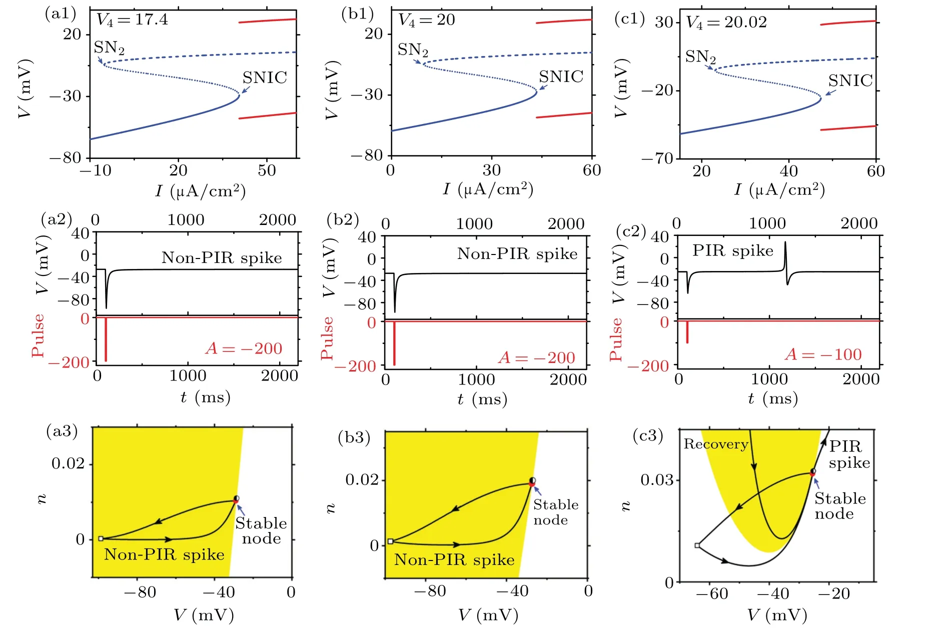
Fig.2.Dynamics at different V4 values in ML model.Top row: Bifurcation diagrams with respect to I.(a1) V4 =17.4 mV.SNIC occurs at I ≈39.96316 μA/cm2;(b1)V4=20 mV.SNIC occurs at I ≈43.41065 μA/cm2;(c1)V4=22.02 mV.SNIC occurs at I ≈47.37691 μA/cm2.Middle row:The response (black, upper panel) of node to inhibitory pulse stimulation (red, lower panel) with width 10 ms.(a2) Non-PIR spike. V4 =17.4 mV,I=39.963 μA/cm2,and pulse strength A=200 μA/cm2;(b2)Non-PIR spike.V4=20 mV,I=43.410 μA/cm2,and A=200 μA/cm2;(c2)PIR spike.V4=22.02 mV,I=47.376 μA/cm2,and A=100 μA/cm2.Bottom row: The threshold curve(i.e.,the border between yellow and blank areas)for the PIR spike and non-PIR spike corresponding to the middle row.Red solid circle is for stable node,black half-filled circle for saddle,and hollow square for the termination of stimulation.The black arrow indicates the trajectory’s running direction.
The geometrical change of threshold curves (i.e., border between blank and yellow areas)for above non-PIR spike and PIR spike are shown Figs.2(a3), 2(b3), and 2(c3), respectively.Such threshold curve effectively distinguishes the dynamic behavior of the trajectory between action potential and subthreshold potential.Trajectories starting from a phase point in the blank region (the spike part) lead to an action potential, while those in the yellow region (the subthreshold part)do not.Shown in red circle is the stable node (resting state),which locates within the subthreshold part (yellow), and in half-filled circle is a saddle point,which locates on the threshold curve.These two points nearly coincide because they are very close to an SNIC bifurcation.The inhibitory stimulationevoked phase trajectory is represented by the black curve,where the square point denotes the termination of stimulation.
For smaller slope ofn-nullcline, i.e.,V4=17.4 mV orV4=20 mV,during inhibitory stimulation,Vvalue decreased from the resting state(red circle)to square point,which locates within the yellow area,as shown in Figs.2(a3)and 2(b3).After the stimulation,Vincreases and recovers to the resting state directly.All behaviors locate within the yellow area, then,no PIR spike is induced.The threshold curve exhibits higherVvalues than that of the resting state and corresponds to the“positive”threshold.
Different from smaller slope ofn-nullcline(V4=17.4 mV or 20 mV),the threshold curve for larger slopeV4=20.02 mV exhibits a part right to the resting state and a part left to the resting state,as shown in Fig.2(c3).The right part of threshold curve exhibitsVvalues larger than the resting state,corresponding to a “positive” threshold.The left part manifestsVvalues smaller than the resting state,corresponding to a“negative”threshold.During the inhibitory stimulation,Vdecreases firstly,then passes through the“negative”threshold curve into blank area, and further decreases to the hollow square.After the stimulation,Vincreases to form the PIR spike, as illustrated in Fig.2(c2),and then recovers to the resting state.Notably,it is the inhibitory stimulation-evoked trajectory running across the threshold curve that forms the PIR spike.
3.2.Decreases in slope of n-nullcline induces PIR spike changed to non-PIR spike in the INap+IK model

Fig.3.Dynamics at different kn values in INa,p+IK model.Top row: Bifurcation diagrams with increasing I.(a1) kn =6 mV and SNIC occurs at I ≈1.145266 μA/cm2; (b1)kn =6.5 mV and SNIC occurs at I ≈1.962412 μA/cm2; (c1)kn =6.95 mV and SNIC occurs at I ≈2.916467 μA/cm2;Middle row: Response (upper) to inhibitory stimulation (lower) with pulse width 1 ms.(a2) Non-PIR spike, kn =6 mV, I =1.145 μA/cm2, and A=200 μA/cm2;(b2)Non-PIR spike. kn=6.5 mV,I=1.962 μA/cm2,and A=200 μA/cm2;(c2)PIR spike,kn=6.95 mV,I=2.916 μA/cm2,and A=100 μA/cm2.Bottom Row: The threshold curve(i.e.,border between yellow and blank areas)for the PIR spike and non-PIR spike corresponding to middle row.Red solid circle is for stable node, black half-filled circle for saddle, and hollow square for the termination of stimulation.The black arrow indicates the trajectory’s running direction.The color codes for yellow and blank areas please refer to Fig.2.
InINa,p+IKmodel, the increase in parameterkncan increase the slope ofn-nullcline.The SNIC bifurcations atkn=6 mV,6.5 mV,and 6.95 mV are depicted in Figs.3(a1),3(b1), and 3(c1), respectively.For SNIC atkn= 6.95 mV(large slope), inhibitory stimulation with relatively weak strength(A=-100 μA/cm2)evokes PIR spike,as depicted in Fig.3(c2), similar to Ref.[47].However, askndecreases to 6.5 mV and 6 mV(small slopes),even strong inhibitory stimulation (A=-200 μA/cm2) cannot induce PIR spike, as depicted in Figs.3(b2)and 3(a2).The initial resting states here are set at the stable node close to SNIC bifurcation in top row of Fig.3, respectively.The changes of threshold curves with increasingknforINa,p+IKmodel resemble those with increasingV4of ML model,as shown in Figs.3(a3),3(b3),and 3(c3).Non-PIR spike forkn=6 mV and 6.5 mV corresponds to“positive”threshold(Figs.3(a3),3(b3)),and PIR spike forkn=6.9 mV corresponds to“negative”threshold(Fig.3(c3)).The codes for the plots and colors here are same with those in Fig.2 and thus the details are omitted to avoid redundancy.
3.3.PIR spike appears for SNIC close to SNHOB in the ML and INa,p+IK model
Above results of PIR spike and non-PIR spike for SNIC bifurcations of ML model andINa,p+IKmodel can be explained with bifurcations in two-parameter plane,as depicted in Fig.4,where left column is for ML model and right column forINa,p+IKmodel.

Fig.4.Bifurcations in two-parameter plane.Green,blue,and black curves denote the SNIC,BHom,and SHom,respectively.Gray is for stable equilibrium and blank for stable limit cycle.In (I,V4) plane of the ML model: (a1) codimension-2 bifurcation points SNHOB (red star) and SNHOS (black star);(a2)enlargement around SNHOB.The three horizontal arrows correspond to the three V4 values in Fig.2.In plane(I,kn)of the INa,p+IK model: (b1)overall perspective of the bifurcations;(b2)enlargement around SNHOB.The three horizontal arrows correspond to the three kn values in Fig.3.
The bifurcations of ML model are shown in Fig.4(a1)and its upper half plane is further enlarged in Fig.4(a2).The bifurcation curve of SNIC(green)exists in a wide range,and the three examples of SNIC in Fig.2 correspond to the red horizontal arrows in Fig.4(a2).For largeV4,the red curve denotes the SN bifurcation(SN1)and the black curve represents the BHom bifurcation.For smallV4, there exists another SN bifurcation curve (SN3, magenta) and a small homoclinic bifurcation curve (SHom, blue).The focus of this paper is the SNIC bifurcation and its PIR spike.To not interrupt such focus,other bifurcations,such as the BHom,SHom,SN1,SN3,and the PIR spike for BHom and non-PIR spike for SHom,are thus shown in Appendix A.As illustrated in Fig.4(a1),the SNIC, SN1, and BHom bifurcation curves contact to form a codimension-2 bifurcation point, saddle-node homoclinic orbit bifurcation(SNHO),which is labeled as SNHOB(red star),where the subscript “B” means that such SNHO bifurcation point is associated with BHom.The SNIC curve intersects with the SN3and SHom curves to form another SNHO, labeled as SNHOS(black star), where the subscript “S” means that the SNHO is associated with SHom.Shown in gray is the mono-stable equilibrium point (resting neuron) and in blank the stable limit cycle (spiking neuron).Coexisting behaviors appear within the very narrow region between the black and red curves upper to the SNHOB.
The three horizontal arrows in Fig.4(a2) correspond to three SNIC bifurcations in Fig.2.The SNIC bifurcations at bottom two horizontal arrows(V4=17.4 mV and 20 mV)correspond to non-PIR spike,and locate far from the SNHOB.To the contrary,the SNIC bifurcation with PIR spike at top horizontal arrow(V4=20.02 mV)locates closely to the SNHOB.Therefore,one speculates that the PIR spike for SNIC appears when SNIC is close to the SNHOB, but does not when SNIC is far from the SNHOB.Furthermore, such a result suggests that border or the transition point between non-PIR spike and PIR spike occurs at certain SNIC bifurcation close to SNHOB.However,one traditional viewpoint is that BT should underlie such border due to the wellknown PIR spike for Hopf bifurcation related to BT.Therefore,our results imply a novel transition point from non-PIR spike to PIR spike, which occurs at certain SNIC bifurcation close to SNHOBinstead of BT.The BT bifurcation locates up-right to the SNHOB(not shown due to the excessively long distance between BT and SNHOB).
Results around the SNHOBare further identified inINa,p+IKmodel, as illustrated in Figs.4(b1) and 4(b2).Figure 4(b2) is the enlargement of the upper half part of Fig.4(b1).ForINa,p+IKmodel, except that there is no SNHOS, the bifurcations are quite similar with those of ML model (Fig.4(a1)).For example, the SNHOB(red star) also appears at the large slope ofn-nullcline (i.e., largekn).The three horizontal arrows in Fig.4(b2) correspond to threeknvalues of SNIC bifurcation in Fig.3.The non-PIR spikes for SNIC bifurcations (at bottom two horizontal arrows withkn=6 mV and 6.5 mV)locate relatively far from the SNHOB.The SNIC bifurcation for PIR spike (at top horizontal arrow withkn=6.95 mV) locates quite close to the SNHOB.Besides, the SNIC for the PIR spike inINa,p+IKmodel in Ref.[47]occurs atkn=7 mV,which also locates quite close to the SNHOB.These results further verify above speculation that PIR spike appears for the SNIC close to the SNHOBbut not for the one far from the SNHOB, which presents a novel viewpoint that the codimension-2 bifurcation point SNHOBplays a determinant role in modulation to the PIR spike.The PIR spike depends upon the distance between the SNIC bifurcation and SNHOB.Such a result extends the conditions for the generation of PIR spike from codimension-1 bifurcation (such as Hopf and BHom) to codimension-2 bifurcation(SNHOB).
In addition,PIR spike appears for the BHom,which is related to the SNHOBand shown in Appendix A.Besides,there is no PIR spike for the SHom, which is associated with the SNHOSand shown in Appendix A as well.
3.4.The relationship between SNHOB and PIR phenomenon in INa,p+IK model with T-type Ca2+ channel
Well known thatTCachannel can mediate PIR phenomena in many neuronal systems.However, the bifurcation mechanism is still unclear up to now.Inspired by above results,the SNHOBis speculated to play such bifurcation mechanism for PIR phenomena mediated byTCacurrent, which is identified in this subsection and depicted in Fig.5.InINa,p+IKmodel withTCacurrent,with increasing the strength ofTCa(i.e.,gT),the SNIC bifurcation (green) changes to BHom (black) via SNHOB(red star).Meanwhile, the neuronal response to inhibitory stimulation changes from non-PIR spike to PIR spike as SNIC bifurcation (green) approaches the SNHOB, as indicated by the red arrows in Fig.5.The details are further depicted in Fig.6.
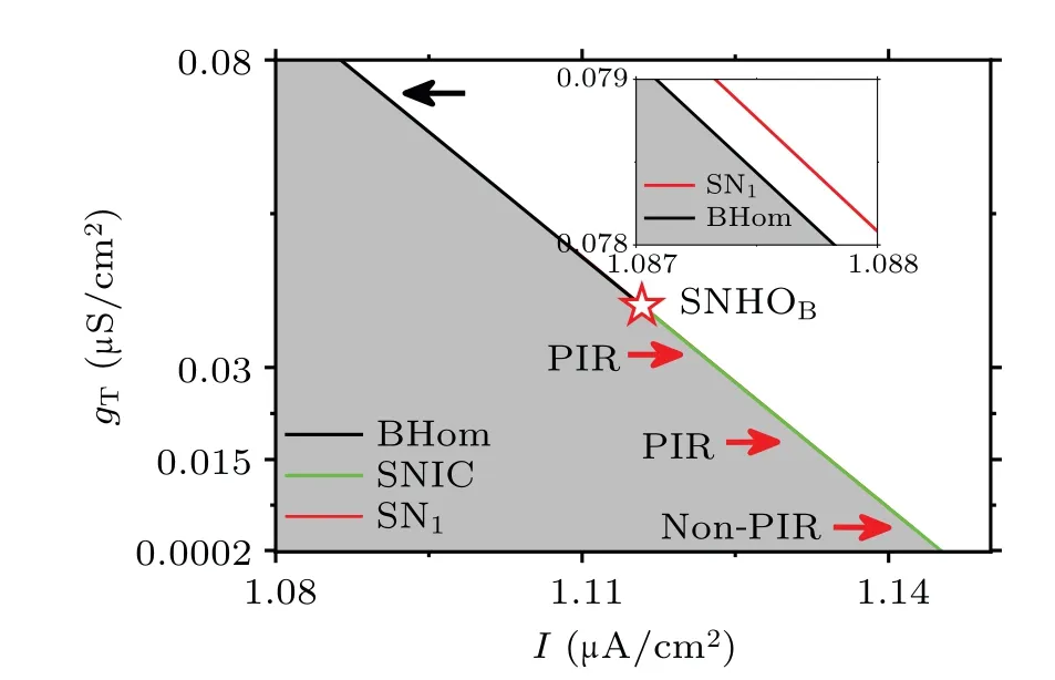
Fig.5.The bifurcations in two-parameter plane (I,gT) related to PIR spike and non-PIR spike in the INa,p+IK model with TCa current.The codes for plots and symbols and colors are same with those in Fig.4.Inset shows the details at black arrow.The dynamics for the SNIC bifurcation at red arrows are shown in Fig.6.
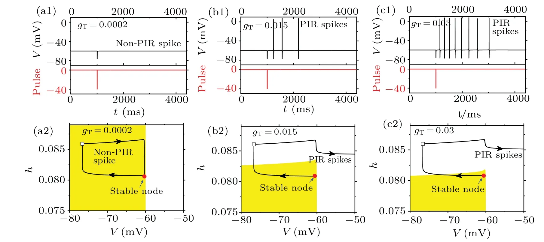
Fig.6.The dynamics at bottom, middle, and top red arrows in Fig.5.Upper row: Membrane potential (upper panel) and pulse stimulation(lower panel).(a1)Non-PIR spike at bottom red arrow for gT=0.0002 μS/cm2 and I=1.145 μA/cm2;(b1)PIR spike at middle red arrow for gT =0.015 μS/cm2 and I=1.134 μA/cm2; (c1)PIR spike at top red arrow for gT =0.03 μS/cm2 and I=1.123 μA/cm2.Lower row: The threshold curve(i.e.,border between blank and yellow regions)for non-PIR spike and PIR spikes in upper row.The color codes for yellow and blank areas please refer to Fig.2.The pulse strength is-40 μA/cm2 and width is 5 ms.
The dynamics at bottom, middle, and top red arrows in Fig.5 are illustrated in Figs.6(a1),6(b1),and 6(c1),wheregT(conductance ofTCacurrent)is 0.0002 μS/cm2,0.015 μS/cm2,and 0.03 μS/cm2, respectively.Upper panel represents the membrane potential(black)and lower panel denotes inhibitory stimulation (red).The initial resting state is set close to the SNIC bifurcation,respectively.Figures 6(b1)and 6(c1)show the PIR spikes appearing at largergT,while figure 6(a1)shows the non-PIR spike at smallergT.The larger thegTis, the shorter latency of the first spike is, and the more the spikes are, as illustrated in Figs.6(b1) and 6(c1).These results resemble experimental observations related to absence seizure and Parkinson diseases to a certain extent.[16,29,31,32]
Figures 6(a2), 6(b2), and 6(c2) provide threshold curves(i.e., border between blank and yellow regions) for the non-PIR spike and PIR spikes in Figs.6(a1), 6(b1), and 6(c1),respectively.These threshold curves result from the projection of threshold surface onto plane (V,h), wherenis fixed at the value of stable node(red solid circle).The square corresponds to the termination of the stimulation.For smallergT(Fig.6(a2)),only“positive”threshold appears and thus the inhibitory stimulation-evoked phase trajectory (black) cannot run across threshold, i.e., forming non-PIR spike.For largergT(Figs.6(b2) and 6(c2)), the “negative” threshold appears and suitable inhibitory stimulation can push neuronal state beyond such threshold to form PIR spikes.Moreover,the larger thegTis, the closer the stable node to the “negative” threshold is,as depicted in Figs.6(b2)and 6(c2),which implies the easier the generation of PIR spikes is.In short, the increase ofTCacurrent brings the neuronal state closer to SNHOB.The closer the neuronal state to SNHOBis,the easier the neuron to elicit PIR spikes is.The shape of “negative” threshold curve here is different from those of Figs.2 and 3 in (V,n) plane,due to threshold curve here is projection of threshold surface onto plane(V,h).
3.5.The relationship between SNHOB and PIR phenomenon in thalamic model
3.5.1.SNHOBbifurcation and PIR spikes
Shown in Fig.7 are the bifurcations in two-parameter plane (I,gT) in the thalamic model.Such a thalamic model not only identifies the role of SNHOBin the PIR phenomenon,but also can be used to simulate the PIR spike observed in thalamic neurons in the experiments related to absence seizure and Parkinson disease.The SNIC (green) changes to BHom(black) via SNHOB(red star) asgTis increased.PIR appears for the SNIC close to SNHOBwhile not for that far from SNHOB,as indicated by the red arrows.The detailed dynamics of PIR spike or non-PIR spike are further depicted in Fig.8.With increasinggT,the inhibitory stimulation-induced neuronal response(black traces in upper panel)changes from non-PIR spike (Fig.8(a)) at smallergT= 0.002 μS/cm2to PIR spikes (Figs.8(b), 8(c)) at largergT=0.3 μS/cm2and 0.6 μS/cm2.The simulation results closely match those of the experimental results.[16,29,31,32,49]
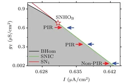
Fig.7.The bifurcations related to PIR spike and non-PIR spike in twoparameter plane(I,gT)in the thalamic model.The codes for plots and symbols and colors are same with those in Fig.5.The detailed dynamics at red arrows are shown in Fig.8 and at blue arrows are shown in Fig.11.
3.5.2.TheTCacurrent for PIR spikes
Moreover, the complex roles ofTCacurrent (i.e.,IT)are shown in middle panels of Figs.8(a)–8(c).ForgT=0.002 μS/cm2, theITis nearly zero before, during, and after the inhibitory stimulation, as depicted in middle panel of Fig.8(a).Then, the behavior is still resting state and no PIR spike is induced.ForgT=0.3 μS/cm2, within the inhibitory stimulation,Vdecreases to a low level,which induces the positiveITdecreased at first and then increased, as illustrated in middle panel of Fig.8(b).After the stimulation,the increased positiveITenhances the membrane potential.Such enhanced membrane potential further activates the potassium channel to elicit a spike or action potential,i.e.,a PIR spike.During such spike, theITfurther increases and then induces the following multiple spikes.Notably, during and after stimulation,ITforgT=0.6 μS/cm2(Fig.8(c)) is much stronger than those ofgT=0.3 μS/cm2(Fig.8(b)), which is the reason that more PIR spikes appear in Fig.8(c)than those in Fig.8(b).
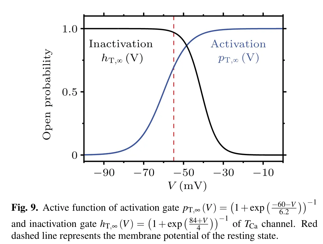
As shown in middle panel of Figs.8(b)and 8(c),TCacurrentIT=-gTp2T,∞(V)hT(V-ET) exhibits complex dynamics.ITincreases not only at low levelV(at the ending part of the inhibitory stimulation) but also at high levelV(during spike), which can be explained by the steady or active functions of activation gate
and inactivation gate
as shown by blue curve and black curve in Fig.9,respectively.The red dashed vertical line denotes theVvalue of the stable node.AsVdecreases,hT,∞(V) increases whilepT,∞(V) decreases.At the ending part of inhibitory stimulation with a reducedVvalue,the increasedhTvalue related to largehT,∞(V)is dominant, whereas decreasedpT,∞(V) plays a minor role,in enhancingIT.AsVincreases,hT,∞(V) decreases whilepT,∞(V) increases, as shown in Fig.9.During a spike with high membrane potentialV, the increasedpT,∞(V) is dominant while the decreasedhTdue to smallhT,∞(V) plays a minor role, resulting in enhancingIT.In a word, the complex cooperation betweenhTandpT,∞(V)determines the enhanced trend ofITcurrent regardless of whether the membrane potential is increased to high level or decreased to low level.
鼻内镜下电凝止血术是治疗鼻出血的微创手术,具有创伤小、痛苦少、恢复快,病人易接受等优势[1],近年来逐渐被公认为治疗鼻出血的首选方法。老年高血压性鼻出血发病急,病情重,进展快,难以自止,处理不当易复发,加上患者紧张、情绪波动会加重出血,后果严重,多数患者需要手术治疗[2]。因此,做好老年高血压性鼻出血的护理对鼻内镜下电凝止血术的疗效具有重要意义。现将2016年1月~2017年12月我科收治的156例老年高血压患者进行回顾与分析。报告如下。

Fig.8.The dynamics at red arrows shown in Fig.7.(a)Non-PIR spike for the bottom red arrow: gT=0.002 μS/cm2 and I=0.641 μA/cm2;(b)PIR spikes for the middle red arrow: gT=0.03 μS/cm2 and I=0.636 μA/cm2;(c)PIR spike for the top red arrow: gT=0.6 μS/cm2 and I=0.631 μA/cm2.In each figure,top,middle,and bottom panels represent the membrane potential,TCa current,and pulse stimulation,respectively.The pulse strength is-2 μA/cm2 and width is 200 ms.
3.5.3.“Positive” and “negative” threshold surfaces
The relationship between PIR spike and threshold surface in phase space(V,hNa,hT)is depicted in Fig.10.For the non-PIR spike in Fig.8(a) with smallgT, the phase trajectory is shown in Fig.10(a1), and the threshold surface is vertical, as depicted by cyan in Fig.10(a2)(local dynamics around stable node (red circle)).Phase trajectory initiating from the space left to the threshold surface results in subthreshold oscillations and right to the surface results in spike.The threshold surface locates right to the stable node (red circle) and exhibitsVvalues lager than the stable node, i.e., a “positive” threshold.During the inhibitory stimulation(prior to the red hollow square which represents the termination of stimulation),Vdecreases and phase trajectory cannot run across the “positive”threshold surface.Then, phase trajectory after the inhibitory stimulation (following the red hollow square) results in non-PIR spike(subthreshold oscillation),as shown in Fig.10(a2).
For the PIR spikes in Fig.8(c) with largegT, phase trajectory is shown in Fig.10(b1), and the threshold surface is approximately horizontal with a maximal value, as shown by pink in Fig.10(b2) (local dynamics around stable node (red circle)).The right part of threshold surface exhibitsVvalues larger than the stable node, whereas the left part manifestsVvalues lower than the stable node, i.e., a “negative” threshold.Phase trajectory initiating from the space lower to the threshold surface(inhNadirection)results in subthreshold oscillations and upper to the surface results in spike.During the inhibitory stimulation,Vdecreases and phase trajectory runs across the left part (“negative”) of the threshold surface into upper space(inhNadirection),resulting in PIR spike after the inhibitory stimulation(Figs.10(b1)and 10(b2)).
Figure 10(c) illustrates the comparison of the threshold surface between small and largegT.The space left to the cyan threshold surface and above the pink cyan threshold surface should be emphasized.Such a space denotes the subthreshold region(phase trajectory initiating from which forms subthreshold oscillation instead of spike) for smallgT, while denotes spike region (phase trajectory initiating from which forms spike instead of subthreshold oscillation) for largegT.The left part of cyan threshold surface exhibitsVvalues lower than that of the stable node, corresponding to the negative threshold and PIR spike.
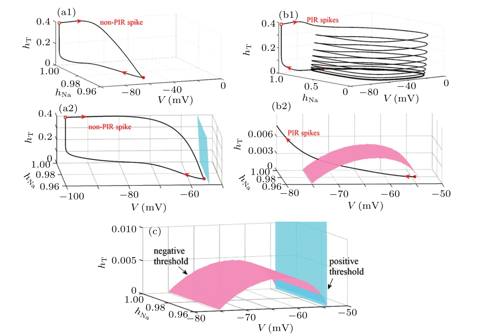
Fig.10.The relationship between threshold surface and phase trajectory.Non-PIR spike in Fig.8(a)with small gT and PIR spikes in Fig.8(c)with large gT.(a1)The phase trajectory for non-PIR spike.(a2)The threshold surface(cyan)for non-PIR spike.(b1)The phase trajectory for PIR spikes.(b2)The threshold surface(pink)for PIR spikes.(c)The superposition of two threshold surfaces in panels(a2)and(b2).
3.5.4.PIR spiking
In addition, for a spiking, the inhibitory stimulation can suppress the spiking to be silent phase at first and then PIR spiking (continuous spikes with much higher frequency) appears after the stimulation,which are similar to the experimental observations[30]and related to absence seizure.[29,32]In the present paper,the enhanced PIR spiking can be simulated for the spiking behavior close to SNHOBand at largegT,as shown in Figs.11(b)and 11(c)(corresponding to middle and top blue arrows in Fig.7),while the PIR spiking is not enhanced for the spiking far from the SNHOBand at smallgT(corresponding to bottom blue arrow in Fig.7), as shown in Fig.11(a).TheTCacurrent for PIR spiking are depicted in the middle panel of Figs.11(b) and 11(c), similar to those of PIR spikes (middle panel of Figs.8(b)and 8(c)).

Fig.11.The dynamics at three blue arrows in Fig.7.(a) Non-PIR spiking for the bottom blue arrow: gT =0.002 μS/cm2 and I =0.66 μA/cm2; (b) PIR spiking for the middle blue arrow: gT=0.03 μS/cm2 and I=0.65 μA/cm2;(c)PIR spiking for the top blue arrow: gT=0.6 μS/cm2 and I=0.64 μA/cm2.In each figure,top,middle,and bottom rows represent the membrane potential,TCa current,and pulse stimulation,respectively.The pulse strength is-2 μA/cm2 and width is 1000 ms.
3.5.5.Comparisons to enhanced firing induced by excitatory modulation
In the present paper, the counterintuitive post-inhibitory rebound spike related to seizure and Parkinson diseases are the focus.To present comprehensive view of the enhanced firing related to seizure, the enhanced firing activity induced by excitatory stimulation is presented, as shown in Fig.12,where the SNIC bifurcation corresponds to that at the middle arrow in Fig.7.For the resting state near such SNIC,excitatory pulse stimulation(lower panel,red)with suitable strength can induce firing activity (upper panel, black), as shown in Figs.12(a1),12(a2),and 12(a3).In addition,static positive or depolarization modulation such as increase of background currentIcan induce enhancement of firing activity, as shown in Fig.12(b)and insets therein.These enhanced firing activities induced by excitatory modulation,and these suppressed firing activities induced by inhibitory modulation, are the common phenomena related to seizures and not the focus of the present paper.
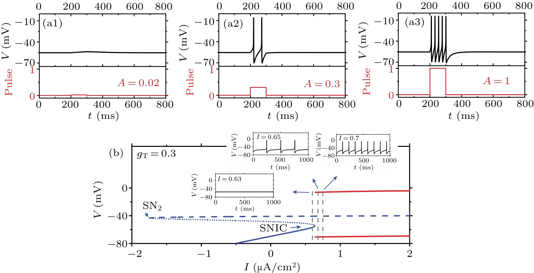
Fig.12.The firing activity induced by excitatory stimulation and background current I.Top row: the response of resting neuron to excitatory stimulation is enhanced with increasing pulse strength A: gT=0.3 μS/cm2 and I=0.63 μA/cm2.The pulse width is fixed at 100 ms.Bottom row:The SNIC bifurcation(right knee of the S-shape curve)corresponds to that at the middle arrow in Fig.7 at gT=0.3 μS/cm2.The neuronal firing activity is enhanced with increasing background current I from 0.63 μA/cm2 (left vertical line),to 0.65 μA/cm2 (middle vertical line),0.7 μA/cm2 (right vertical line).The details for bifurcation diagram please refer to Fig.2.
4.Conclusions and perspectives
PIR spike, which is induced by inhibitory modulation,is closely linked to important nonlinear concepts such as threshold and bifurcations.This phenomenon is also associated with various brain functions and diseases, including absence seizure and Parkinson diseases.[16,26–32]Therefore, understanding how to modulate the PIR spike is crucial for both nonlinear physics and neuroscience.This paper investigates the PIR spike and its relationship to threshold and bifurcations(codimension-1 and -2) by modulating multiple parameters,including the T-type Ca2+channel, in various models.The results exhibit significances in the following aspects.
Firstly,our study uncovers a universal codimension-2 bifurcation mechanism for the PIR spike.Such a bifurcation called saddle-node homoclinic orbit(SNHOB)is identified in 4 neuronal models especially including the thalamic model.Moreover,multiple parameters can be modulated to induce the appearance of SNHOB.Our study finds that PIR spike does not appear for the SNIC far from the SNHOB,but for the SNIC close to the SNHOB.Such a result extends the codimension-1 bifurcations for PIR spike from Hopf and BHom in the previous studies[1,18]to SNIC.Additionally,it reveals a new border between non-PIR spike and PIR spike,which occurs at a certain SNIC bifurcation close to SNHOB.Previous studies have suggested that such border is BT due to the PIR spike for Hopf bifurcation.[48,49]Therefore,our results present codimension-2 bifurcation underlying PIR spike, provide comprehensive recognitions between PIR spike and bifurcations, bring novel viewpoint for the transition between non-PIR spike and PIR spike.
Secondly,SNHOBprovides a dynamical interpretation to the seemingly contradictory result of SNIC for non-PIR spike in the ML model[1]and PIR spike in theINa,p+IKmodel.[47]By changing slope ofn-nullcline,the SNIC for non-PIR spike in the ML model is identified to be far from the SNHOB,while that for PIR spike in theINa,p+IKmodel is close to the SNHOB.The increase of slope ofn-nullcline induces the SNIC bifurcation to be close to the SNHOB, which is the essential reason for the appearance of PIR spike for both models.Then,the modulation to the slope of then-nullcline presents a feasible measure to modulate the PIR spike.
Finally, the SNHOBthat underlies the PIR phenomena mediated byTCachannel provides a dynamic interpretation for experimental observations[16,26,29–32]of the absence seizure and Parkinson diseases induced by inhibitory stimulation.By increasing the conductance of theTCachannel, which modulates SNIC to be closer to the SNHOB,the inhibition-inducedTCacurrent becomes stronger,leading to the appearance of PIR spikes or PIR spiking.Such enhancement of neuronal behavior induced by inhibition has been identified as a factor in the pathogenesis of absence seizure and Parkinson diseases.To relieve seizure or Parkinson diseases by inhibiting pyramidal neurons, a crucial step is to avoid the PIR phenomena.This can be achieved, for example, by modulating the behavior of pyramidal neurons to be SNIC far from the SNHOBthrough decreasing the conductance ofTCacurrent.In addition, the complex evolution process ofTCacurrent in the generation of PIR phenomenon is obtained.These results provide not only bifurcation mechanism for pathogenesis of seizure or Parkinson diseases,but also new perspective on treatment options.
In the future,further studies on PIR spike should be conducted in the following areas.Firstly,theoretical explanations for PIR spike and additional factors that modulate PIR spike should be provided.Secondly,dynamical mechanisms for PIR spike should be investigated in more neuronal and network models to explore brain functions or diseases, by modulating other factors such as synapse.Finally,a comparison between PIR spike mediated by theTCachannel and hyperpolarizationactivated cation current (Ih) should be conducted.This will provide a deeper understanding of the similarities and differences between the two mechanisms and their respective roles in brain function and diseases.
Appendix A
Three figures are provided to represent the SHom and BHom orbit bifurcations shown in Fig.4(a1), equilibrium point and phase trajectory, and PIR spike or not in the ML model,respectively.
Figure A1 represents the SHom and BHom bifurcations atV4=7.3 mV(Fig.A1(a))andV4=23 mV(Fig.A1(b))in the ML model,respectively.Except for SHom or BHom,the SN1and SN3denote saddle-node bifurcation of equilibrium point,which correspond to the bifurcation curves of SN1and SN3in Fig.4(a1).The difference of SHom and BHom can be well interpreted from their phase trajectories,which are depicted in Fig.A2.

Fig.A1.The homoclinic orbit bifurcations in the ML model.SHom and BHom denote the small and big homoclinic orbit bifurcation, respectively.SN1 and SN3 represent saddle-node bifurcation of equilibrium point.The details for other plots please refer to Fig.2.(a)V4=7.3 mV and SHom occurs at about I =36.5683 μA/cm2; (b)V4 =23 mV and BHom occurs at about I=49.62212 μA/cm2.
Shown in Fig.A2(a)is the phase trajectory for SHom orbit and in Fig.A2(b)the one for BHom orbit.These two trajectories both begin from and end at the saddle(half-filled circle)and run in anti-clockwise.Such closed orbit is the homoclinic orbit.The BHom orbit is big,which contains the stable node(red solid circle),as illustrated in Fig.A2(b)(the insert figure is enlargement around the node and saddle).

Fig.A2.The homoclinic orbit (black curve) and the stable node (red solid circle), saddle (half-filled circle), and unstable focus (hollow red circle).(a) SHom orbit in Fig.A1(a); (b) BHom orbit in Fig.A1(b).Inset shows the details around the saddle and stable equilibrium points.
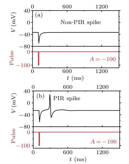
Fig.A3.The inhibitory stimulation-induced responses (black, upper panel) initiating from the resting state close to homoclinic orbit bifurcations in Fig.A1.Lower panel represents the inhibitory stimulation(red)(strength A=-100 μA/cm2 and pulse width 10 ms).(a)Non-PIR spike induced from resting state at V4=7.3 mV and I=36.568 μA/cm2(close to SHom bifurcation in Fig.A1(a));(b)PIR spike induced from resting state is set at V4 =23 mV and I =49.620 μA/cm2 (close to BHom bifurcation in Fig.A1(b)).
In addition, the unstable focus (hollow red circle) is within the BHom orbit.However, SHom orbit (Fig.A2(a))is small, and the stable node locates outside.From the geometrical characteristics, the BHom is favorable for PIR spike whereas the SHom not.As expected, for BHom bifurcation,PIR spike is induced, as illustrated in Fig.A3(b), and the non-PIR spike appears for SHom bifurcation,as illustrated in Fig.A3(a).The lower panel represents the inhibitory stimulation(red)and the upper panel denotes the membrane potential(black).More details about the PIR for BHom please refer to Ref.[18].The SHom bifurcation here is close to the SNHOSin Fig.4(a1).The non-PIR spike for such SHom implies that SNHOSdoes not have the role to guarantee the PIR spike in ML model.
Acknowledgements
Project supported by the National Natural Science Foundation of China (Grant Nos.12072236, 11872276, and 11802086), the Postdoctoral Research Project of Henan Province, China (Grant No.19030095), and the Science and Technology Development Program of Henan Province,China(Grant No.212102210543).
猜你喜欢
杂志排行
Chinese Physics B的其它文章
- Robustness of community networks against cascading failures with heterogeneous redistribution strategies
- Identifying multiple influential spreaders in complex networks based on spectral graph theory
- Self-similarity of complex networks under centrality-based node removal strategy
- Percolation transitions in edge-coupled interdependent networks with directed dependency links
- Important edge identification in complex networks based on local and global features
- Free running period affected by network structures of suprachiasmatic nucleus neurons exposed to constant light
