Magnetic-field-controlled spin valve and spin memory based on single-molecule magnets
2023-10-11ZhengzhongZhang张正中RuyaGuo郭儒雅RuiBo薄锐andHaoLiu刘昊
Zhengzhong Zhang(张正中), Ruya Guo(郭儒雅), Rui Bo(薄锐), and Hao Liu(刘昊),‡
1Faculty of Mathematics and Physics,Huaiyin Institute of Technology,Huai’an 223003,China
2Nano Science and Technology Institute,University of Science and Technology of China,Suzhou 215123,China
Keywords: single-molecule magnet,spin dependent electron tunneling,spin valve
1.Introduction
Spintronics aims to exploit the spin degree of freedom in solid-state devices for data storage and information processing technologies.[1]The spin valve(SV),a principal spintronic device, is a microelectronic device in which high-resistance(HR) and low-resistance (LR) states are realized by using both the charge and spin of carriers.[2,3]A standard magnetoresistance (MR) SV is an electronic device in which two conducting magnetic layers are separated by a nonmagnetic layer.[4,5]By applying an external magnetic field, considerable resistance switching can be achieved in the device by altering the magnetic configuration of the electrodes between parallel/LR and antiparallel/HR states.To date, various SV devices have been successfully manufactured, and the discoveries of giant magnetoresistance[6](GMR) and tunneling magnetoresistance[7](TMR)in metallic SV devices have revolutionized applications such as magnetic recording and memory.
Generally, the magnetic layers in SV devices are composed of ferromagnetic (FM) metals.With the development of materials science, molecule/organic-based magnets, which allow chemical tuning of electronic and magnetic properties, have become a promising new class of magnetic materials for future spintronic applications.[8–13]Among these magnets,single-molecule magnets[14–17](SMMs),a new type of quantum magnetic material, have attracted increasing attention for their potential applications in novel spintronic devices.[18–20]The inner magnetic core of these molecules is surrounded by organic ligands, and the interaction between the magnetic cores of neighboring molecules is very weak,which leads to a large ground-state spin of SMMs.[21,22]This large ground-state spin of an SMM results in a doublewell energy potential, which can resist magnetization reversal under low-temperature conditions.[17,23,24]Experimentally, electron transport of SMMs was observed with scanning tunneling microscopy and mechanically controllable break junctions,[25–30]although some results remain to be clarified.[31–35]More importantly, some studies have shown that electronic properties of these special molecules can be precisely controlled by electrical or magnetic means.[36–40]To date, many interesting phenomena of electron transport through SMMs have been discussed, such as spin blockade effect,[41,42]spin diode effect,[43,44]spin-Seebeck effect,[45,46]spin torque effect,[47–49]Kondo effect,[50–52]and superconducting effect.[53]According to studies of Boganiet al.,these molecules will be trapped in one of two metastable ground states±S, and only electrons whose spin direction is parallel to the molecular magnetism can pass through the SMM, resulting in high spin polarization of the tunneling current.[54]Due to this property,SMMs seem to be appropriate candidates for designing nanoscale spintronic devices, for example, spin filters or SV devices.[55,56]
In this work, we observe a spin-valve-like signal in our SMM-magnetic tunnel junction(MTJ)system,which consists of a magnetic molecule sandwiched between an FM lead and a nonmagnetic (NM) lead.A small detecting bias voltage is applied between two electrodes,and the conducting electrons are controlled by adjusting the external magnetic field.We observe a stable LR state under positive applied magnetic fields,a stable HR state under negative fields and HR–LR switching depending on the magnetization reversal of the SMM.Although much work on the spin-resolved transport properties of SMM molecules has been performed,[57–61]studies about the HR–LR switching effect controlled by magnetic signals in an SMM and the corresponding properties remain lacking.This work aims to fill this gap.
2.Model and Hamiltonian
As shown in Fig.1(a), the magnetic molecular junction we consider here consists of an SMM placed between two metallic electrodes in the presence of an external magnetic field.The total Hamiltonian of this structure is composed of two parts,i.e.,Htotal=Horbit+Hspin,[41,62]
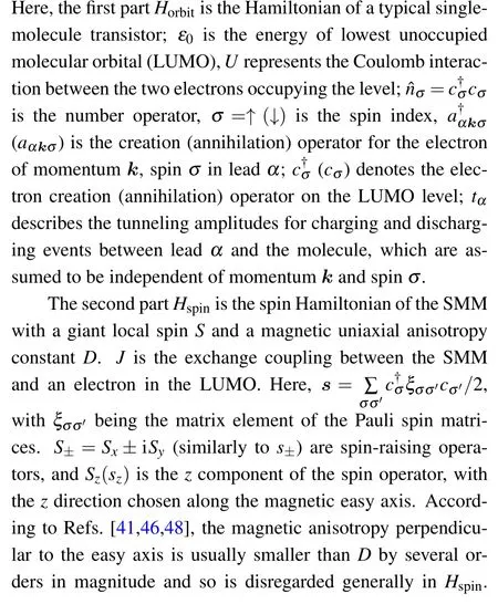
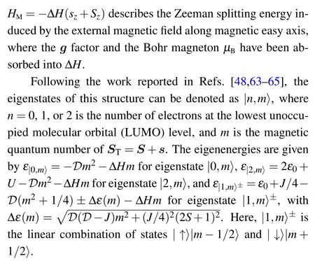
At low temperature,the transport process is dominated by the sequential tunneling through the SMM energy level,while the co-tunneling and direct tunneling can be neglected safely.For the weak coupling between the SMM and leads,the master equation approach holds.The spin-σcurrent can be written asIσ=(ILσ-IRσ)/2,whereILσ(IRσ)represents the spin current flowing from the left(right)lead to the SMM:

Some techniques that can accurately deal with the time-dependent evolution in SMM systems have been developed,[57,58,66,67]and in this paper,we choose the numerical method suggested in Refs.[41,68,69].The time evolution can be studied by solving the master equation,which assumes that the kernel does not depend on time.[59]Then, the time dependence of probabilityPi(t) can be obtained by solving a series of equations
and steady-state probabilityPi(t →∞)can be obtained by applying the condition dPi/dt=0.The total tunneling current isI=∑σ(ILσ-IRσ)/2,and the spin polarization coefficient of the current is defined asη=(I↑-I↓)/I.
3.Result and discussion
In the following discussions we adopt the parameters based on experiments and first-principles calculations for Mn12-ac molecule[23,31,70]withS=10,D=0.06 meV, andU= 25 meV.This magnetic molecule has two degenerate ground states ofS=±10 and a relatively large tunneling barrierDS2≈60 K.The exchange coupling parameterJis taken to be positive (J= 0.1 meV), meaning that the coupling is ferromagnetic.[55]Since the next higher energy orbital lies about 8 meV above the LUMO,[71]the higher orbitals are expected to affect the results very weakly in the low-bias voltage regime.
First,we demonstrate how to use a magnetic field to manipulate the HR–LR switching in this SMM-MTJ.Figure 2 shows the magnetization of the SMM and the tunneling current change as functions of the external magnetic field, with a small bias voltageV=1.0 mV exerted across the junction and equilibrium temperatureT=1 K.The arrows show the magnetic field scanning direction, and the scanning process is assumed to be slow to ensure that the system can relax to the steady state.As shown in Fig.2(a), the magnetization of the SMM exhibits a loop structure when the magnetic field is scanned back and forth.The positive applied magnetic field will flip the SMM to the +S(parallel configuration) spin direction,andvice versa.Due to the intrinsic magnetism of the SMM,the molecules will preserve their spin states during the gradual reduction of the external magnetic field.Therefore,in the region close to ΔH=0,both SMM spin states±Scan be retained.In Fig.2(b),we plot the electron current as a function of ΔH.If we useI+to denote the current when ΔHis scanned from+3 meV to-3 meV,andI-to denote the current when the magnetic field is scanned in the opposite direction, then we can find that the electron tunneling spectraI+andI-are quite different.When the magnetic field ΔHis scanned from+3 meV to-3 meV, we observe a large current plateau (LR state) in the window of ΔH ∈[-0.5,2]meV.This current increases as the spin polarization of the FM electrode increases.When the magnetic field is scanned in the opposite direction,a similar but relatively small current plateau(HR state)appears in theI-spectrum near ΔH ∈[-2,0.5] meV, while this current is significantly smaller thanI+in the LR state.UnlikeI+,a higher spin polarization in the electrode will significantly weakenI-.Moreover, in the zero-magnetic field (ZF) point(ΔH=0), the resistance of the molecular junction obviously presents two different states.Both of HR and LR states can be saved at the ZF point.This external magnetic field-controlled HR–LR switching effect is very similar to that in traditional SV devices.[4]The difference is that one of the magnetic layers in the traditional MTJ has been replaced by a magnetic molecule in our system.

Fig.1.(a)Schematic diagram of a molecular-MTJ proposed in this paper,which consists of an SMM coupled to an FM lead and an NM lead.(b) Schematic illustration of the “HR–LR” switching by applying an external magnetic field and a small bias voltage.
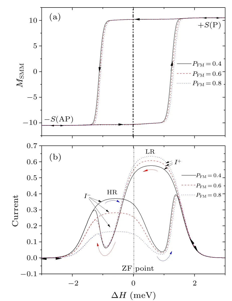
Fig.2.(a) Magnetic hysteresis loops of the SMM and (b) tunneling currents(scaled by eΓ0/¯h)varying when the external magnetic field ΔH is scanned back and forth,with different lead’s spin polarizations.The equilibrium temperature and bias voltage are T =1 K and V =1 mV,respectively.
The HR–LR switching phenomenon illustrated in Fig.2 can be simply explained as follows: As shown in Fig.1(b),a magnetic field will destroy the bistable ground states of the SMM, resulting in a change in the SMM magnetic moment.The bias is not large enough to affect the magnetism of the SMM in the absence of a magnetic field.Therefore,in Fig.2(b), we can observe two different resistance states near the ZF point.If the magnetic field is scanned from +3 meV to 0 meV,then the core spin of the molecule will be flipped by the external magnetic field to the+Sspin state(parallel to the magnetism of the FM electrode).Then, the SMM will tend to allow spin-up (majority) electrons in the FM electrode to pass through the junction, and the device will present an LR state.In contrast, if the magnetic field is scanned in the opposite direction, then the antiparallel magnetic configuration will be maintained at the ZF point,and the molecule will favor spin-down (minority) electron flow through the device.As a consequence,an HR state is presented.
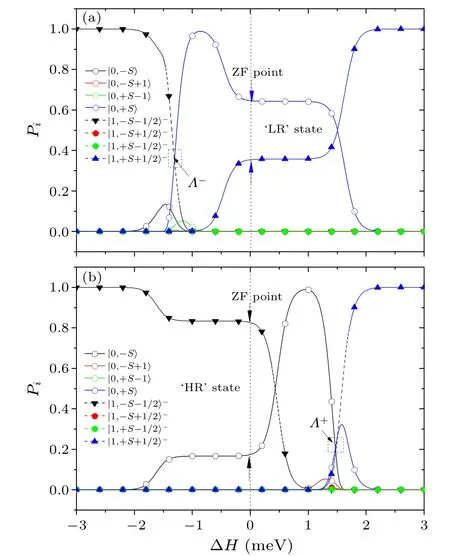
Fig.3.Variations in the molecular state probabilities (a) as ΔH is scanned from +3 meV to -3 meV and (b) as ΔH is scanned from-3 meV to+3 meV.The equilibrium temperature and bias voltage are given as T =1 K and V =1 mV.
To explain the physical process in Fig.2 more clearly,we calculate the variation in the probabilities of the SMM statesP|0,S-1〉,P|0,-S+1〉,P|0,±S〉,P|1,±S±1/2〉-andP|1,±S∓1/2〉-as the magnetic field is scanned back and forth.In Fig.3(a), the external magnetic field ΔHis slowly scanned from+3 meV to-3 meV to allow the system to relax to the steady state.When ΔH >2.0 meV, all states are unoccupied except for|1,+S+1/2〉-(P|1,+S+1/2〉-=1),which means that the molecule spin state is pinned in the +S(parallel to the FM electrode) spin direction and that one spin-up electron is trapped in the SMM.Due to the Coulomb repulsion energy of the SMM(UMn12-ac≈25 meV)and small applied bias voltage,this trapped electron cannot hop into the NM electrode,and the electron current is completely blocked.When ΔHdecreases from +2.0 meV to-0.3 meV, the probabilityP|0,+S〉quickly increases, and the tunneling current is dominated by the transition between two states:|0,+S〉↔|1,+S+1/2〉-.According to Refs.[41,63],only spin-up electrons in this case can tunnel through the LUMO level in the molecule,resulting in a spin-up polarized electron current.Because the FM lead is spin-up polarized,the spin majority(up)electrons are easily transported through the SMM,and an LR state is obtained.If we assume the temperatureT →0, the current in the LR state and ZF condition can be approximated as
If ΔHis further decreased to the window of [-2.0 meV,-0.3 meV], then inelastic tunneling processes will occur.In this regime, the bistable energy spectrum of the SMM is completely destroyed, and nearly all the spin states of the molecule have a non-zero probability of being occupied.Among these states,the probabilities of the two special states|0,+S〉 and|1,-S-1/2〉-are much larger than those of the other states.The point at whichP|0,+S〉=P|1,-S-1/2〉-exactly corresponds to the magnetism reversal point in Fig.2(a),indicating that the molecular spin direction starts to reverse from + to- due to the magnetic field.As ΔHcontinues to vary, all the state probabilities return to 0 except for that of|1,-S-1/2〉-(P|1,-S-1/2〉-=1), which implies that the SMM spin state is pinned in the-Sdirection and that the tunneling current will be switched “off” by one spindown electron blocking the electron tunneling channel at the LUMO level.If the magnetic field is scanned in the reverse direction (ΔHchanges from-3 meV to +3 meV; see Fig.3(b)), then similar physical phenomena will occur.The SMM magnetic reversal point from- to + corresponds to the point whereP|0,-S〉=P|1,+S+1/2〉-, and the electron tunnelling process in the HR window is dominated by the transition|1,-S-1/2〉-↔|0,-S〉, which means that only spin minority(down)electrons can flow through the molecule.At low temperatures,the spin-down polarized electron current in the HR state and ZF condition yields
If we defnie a parameter MR=to describe the on-off ratio of LR-HR switching, then the MR ratio under low temperature and ZF condition can be given as
Similar to the results of the Julli`ere’s model,[1]from Eq.(7)we can determine that the MR ratio mainly depends on the spin polarization of the electrode.The higher the spin polarization of the FM lead is,the greater the MR ratio of the device,and the better the device functions as an SV device.
Next, we discuss the effect of the equilibrium temperature on this device.For ease of description, we useΛ-to denote the reversal point when the spin state of the SMM switches from + to- andΛ+to denote the reversal point from- to +.As shown in Fig.4(a), the magnetic hysteresis loop shrinks and the distance betweenΛ+andΛ-decreases with increasing temperature.As mentioned in regard to Fig.3, the magnetism reversal pointΛ+corresponds to the point whereP|0,-S〉=P|1,+S+1/2〉, andΛ-corresponds to another point whereP|0,+S〉=P|1,-S-1/2〉-.Therefore, in Fig.4(c),we plot the state probabilitiesP|0,S〉andP|1,-S-1/2〉-as functions of ΔHwhen the magnetic field is scanned from+3 meV to-3 meV under different equilibrium temperatures.As shown in Fig.4(c), a higher temperature will excite these two states to participate in the transition earlier, which will lead to the molecular magnetic moment being more prone to flipping.As a result, the absolute values ofΛ+andΛ-will decrease with increasing temperature.In addition, with decreasing temperature, the shape of the current spectra in the HR and LR states gradually evolves into a plateau.We take the current in the LR state as an example.As discussed in regard to Fig.3,the current in the LR state is dominated by the transition|0,+S〉↔|1,+S+1/2〉-.Therefore, in Fig.4(d),we plot the probabilities of these states as functions of ΔH.A lower temperature causes the electron tunneling process to be more easily dominated by the transition between the two states|0,+S〉and|1,+S+1/2〉-,resulting in the gradual evolution of the current distribution into a plateau.In contrast,a higher temperature will excite more spin states to participate in the tunneling process, which will reduce the spin polarization of the current and,to a certain extent,narrow the LR(HR)state window.
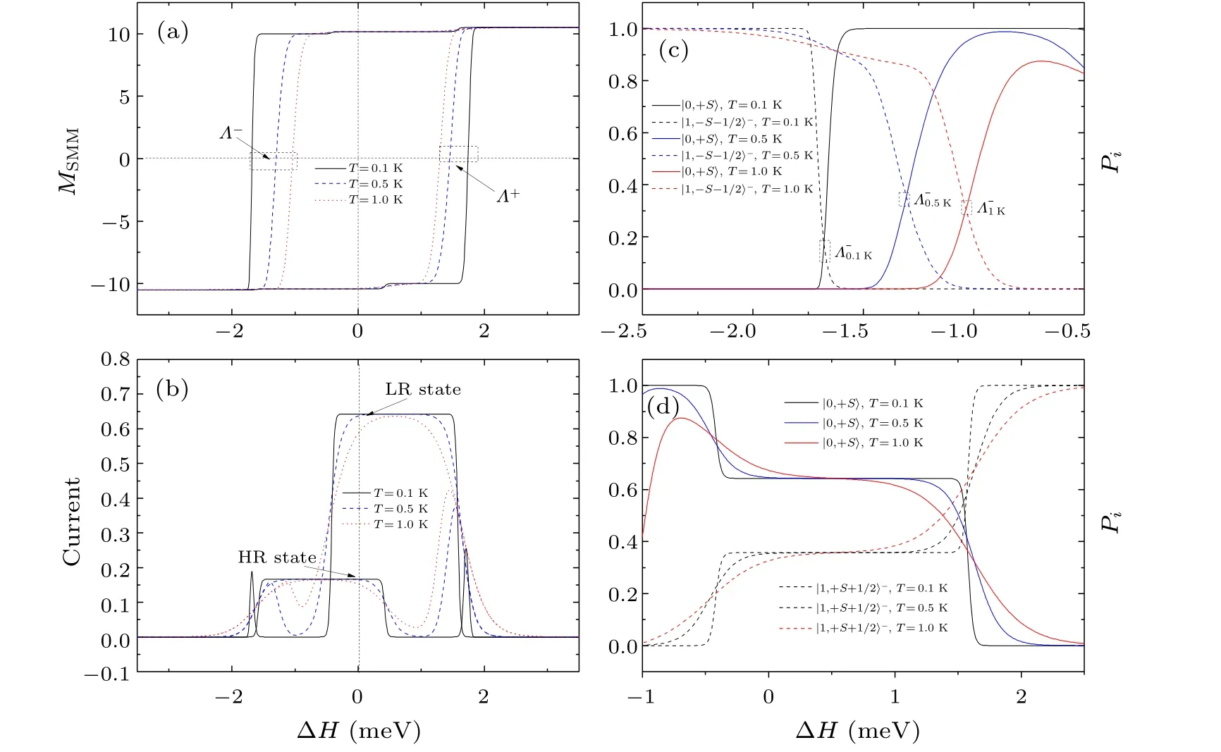
Fig.4.(a) Magnetic hysteresis loops of the SMM and (b) tunneling currents (scaled by eΓ0/¯h) varying when the external magnetic field ΔH is scanned back and forth, with different temperature and bias V =1.0 mV.(c) and (d) Variations in the molecular state probabilities(c)P|0,+S〉 and P|1,-S-1/2〉- and(d)P|0,+S〉 and P|1,+S+1/2〉 as ΔH is scanned from+3 meV to-3 meV.
Finally, let us discuss how to implement the device scheme proposed in this paper under a real experimental environment.In Fig.5, we use a time-varying magnetic field with an amplitude ΔH=±0.8 meV(approximately 5.5 T)to“write” the resistance state in this device.According to the experimental work of Joet al.,[72]such a magnetic field can be achieved under the current experimental conditions.The train of magnetic field signals applied to the SMM periodically changes its direction every 2×10⁵¯h/Γ(~= 4 μs forΓ=8 GHz[69]).As shown in Fig.5(a),this time-varying magnetic field signal only lasts 2 μs every time to reach±0.8 meV and then quickly reduces to zero.Figure 5(c) shows that the SMM can maintain its magnetization(remain in the+Sor-Sspin state) when the magnetic field disappears.To detect the HR–LR switching in this device,we apply a small bias voltageV=0.5 mV across the two electrodes.As shown in Fig.5(b),we calculate the current spectrum changes with the magnetic field variation.The tunneling current can clearly be switched between the“HR”and“LR”state by this time-varying external magnetic field.Even with a relatively low spin-polarized FM electrode(PFM=0.3,close to the spin polarization of the metal Ni[73,74]) and higher temperatureT=2 K, the MR ratio at ZF point can reach almost 0.38,which is very consistent with the prediction of Eq.(7).Interestingly, every time the sign of the magnetic signal changes, the electron current obviously oscillates and soon stabilizes to a new plateau.This unusual electrical signal is instantaneous and disappears with the completion of the molecular magnetic inversion process.Therefore,observing the generation and disappearance of this signal may yield effective evidence to judge whether magnetic reversal of the molecular magnetism has been completed.Furthermore, as shown in Fig.5(d), regardless of how the polarization of the FM electrode changes,the spin polarization parameter of the electron currentηcan always vary from +1 to-1.This shows that not only the resistance state but also the current spin polarization parameter in this system can be rewritten by a magnetic field.
4.Conclusions
In summary,we have proposed a supramolecular SV consisting of an SMM and an FM electrode.By adjusting the magnetic field,the core spin of the molecule can be switched between two bistable magnetic ground states|±S〉,leading to a parallel(LR)or an antiparallel(HR)magnetic configuration of the system.Our numerical results show that the device resistance depends on the spin alignment of the MTJ,which can be controlled by an external magnetic field and read out by a small bias voltage.More interestingly, due to the intrinsic magnetism of the SMM, this HR/LR state can be saved and readout under a ZF condition.The results in this work offer a starting point to study multilayer structures combined with molecular magnets,such as SMM spin-valve structures.However, the functional ability of the device greatly depends on the molecular magnetic characteristics, a relatively low equilibrium temperature and an FM electrode.
Acknowledgments
This work was supported by the National Natural Science Foundation of China (Grant No.11404322), the Natural Science Foundation of Huai’an (Grant Nos.HAB202229 and HAB202150), and the Natural Science Foundation of the Jiangsu Higher Education Institutions of China (Grant No.22KJD140002).
猜你喜欢
杂志排行
Chinese Physics B的其它文章
- Robustness of community networks against cascading failures with heterogeneous redistribution strategies
- Identifying multiple influential spreaders in complex networks based on spectral graph theory
- Self-similarity of complex networks under centrality-based node removal strategy
- Percolation transitions in edge-coupled interdependent networks with directed dependency links
- Important edge identification in complex networks based on local and global features
- Free running period affected by network structures of suprachiasmatic nucleus neurons exposed to constant light
