Asymmetric magnetoimpedance effect and dipolar interactions of FINEMET/SiO2/FePd composite ribbons
2023-09-05YongBinGuo郭永斌DaoWang王岛ZhongMinWang王忠民LeiMa马垒andZhenJieZhao赵振杰
Yong-Bin Guo(郭永斌), Dao Wang(王岛), Zhong-Min Wang(王忠民),†,Lei Ma(马垒), and Zhen-Jie Zhao(赵振杰)
1Key Laboratory of UWB&THz of Shandong Academy of Sciences,Institute of Automation,Qilu University of Technology(Shandong Academy of Sciences),Jinan 250014,China
2College of Science,Qiongtai Normal University,Haikou 571127,China
3School of Materials Science and Engineering,Guilin University of Electronic Technology,Guilin 541004,China
4Engineering Research Center for Nanophotonics and Advanced Instrument,School of Physics and Electronic Science,East China Normal University,Shanghai 200241,China
Keywords: asymmetric giant magnetoimpedance,FePd film,composite ribbons
1.Introduction
Magnetic materials exhibit many new physical phenomena, such as magnetostriction (MS),[1]magnetocaloric effect (MCE),[2]giant magnetoresistance (GMR),[3]and giant magneto-impedance(GMI),which have rarely been studied.[4]Soft magnetic materials have been widely used due to their high saturation magnetization, low coercivity, and high permeability.[5,6]GMI effect is the changing of the impedance experienced by an AC current flowing through a magnetic material with external DC magnetic field.[7]Asymmetric giant magneto-impedance(AGMI)is another form of GMI discovered in 1995.[8]The asymmetric magneto-impedance enhances the linear near-zero field.The magnetic sensors made of soft magnetic composite materials and based on GMI and AGMI have high sensitivity, small size, and easy integration.That is why such magnetic sensors are widely used in biomedical testing,[9]space research, aerospace applications,[10]car sensing systems,[11]and magnetic guidance systems.[12]It has been shown that the AGMI can be obtained by applying a DC bias current or a small magnetic field to a soft magnetic conductor.[13–15]However, from a technical and practical point of view,this approach is unfavorable,mainly due to high energy consumption.Recent studies have shown that the AGMI response can also be achieved by using magnetostatic interactions like exchanging bias fields between soft magnetic materials and antiferromagnets.[14,16,17]However, these studies ignored the influence of dipolar interactions on the bias field.In the magnetic sensors, the magnetizations of soft magnetic materials are modulated by exchange coupling and magnetic dipole interactions in the external magnetic field.[18]The dipolar interactions are long-range interactions that can strongly modify the magnetic response of the system to external excitation.[19]The explanations for the AGMI of composite materials mainly focus on exchange coupling and ignore the magnetic dipole interactions.[20–22]Recently, it has been found that inserting an insulating layer between magnetic layers can further increase the GMI.[23–25]This study did not clarify the further increase of the GMI from the perspective of magnetic interactions.However,that study gave ideas for using composite materials in structural designs.The insulating layer in the magnetic layers can directly eliminate the influence of interface exchange coupling and reveal the influence of the dipole interactions on the bias field.In recent years,FePd films have been used in ultra-high-density magnetic recording media and magnetic random access memory devices.Hence,FePd films can be used as coating layers.[26–28]A three-layer structure of FINEMET/SiO2/FePd composite ribbons was also designed.
In this work, the FINEMET/SiO2/FePd composite ribbons with different thicknesses of SiO2layer are successfully prepared.The morphology,magnetic properties,magnetic domain structure, and asymmetric giant magneto-impedance of FINEMET/SiO2/FePd composite ribbons are studied.Moreover, a dipolar model is established, and the physical mechanism of the generation of the bias field and the asymmetric giant magneto-impedance are explained by using the concept of dipolar interactions.
2.Experimental methods
The Fe-based amorphous ribbons with thickness of 33µm and width of 0.6 mm are prepared by the melt-spinning method,[29]and cut to a size of 2 cm in length.The FINEMET ribbon can be obtained by annealing amorphous ribbon at 540◦C for 20 min, and the vacuum value is 9.8×10⁻⁵Pa.The ribbon has two different surfaces: the free ribbon surface and wheel-side ribbon surface with different roughnesses.The free ribbon surface spurted SiO2and FePd film were deposited by RF magnetron sputtering with a base pressure of 1.0×10⁻⁴Pa, and an argon atmosphere with a constant pressure of 0.8 Pa during sputtering.The SiO2layer with thicknesses of 10 nm, 20 nm, 50 nm, 80 nm, and 100 nm was sputtered on the free ribbon surfaces of the FINEMET ribbon up to 25-nm-thick FePd film.The structures of FINEMET/SiO2/FePd composite ribbons are shown in Fig.1.The surface morphology of FINEMET/SiO2/FePd composite ribbons was observed by using Hitachi S-4800 scanning electron microscope(SEM).The domain structure was tested by magneto-optical Kerr microscope(EVICO Magnetics)in the longitudinal geometry,to image on the surface of the coated and uncoated FINEMET ribbons,with the magnetic field applied along the sample axis.The hysteresis loops of FINEMET/SiO2/FePd composite ribbons were tested by the Lake-shore 7404 vibrating sample magnetometer (VSM), with the magnetic field parallel to the longitudinal axis of samples.The magneto-impedances of FINEMET/SiO2/FePd composite ribbons were measured by the impedance analyzer HP4294A.In order to eliminate the influence of geomagnetism, the coils were placed perpendicular to the direction of geomagnetism.The device of magnetoimpedance measurement is shown in Fig.2.The frequency of the alternating current ranges from 100 Hz to 100 MHz and the amplitude is kept at a constant value of 10 mA, respectively.The composite ribbons were subjected to the maximum external direct current magnetic field ranging from−90 Oe(1 Oe=79.5775 A·m−1)to 90 Oe, which was generated by a pair of Helmholtz coils.The MI ratio is defined as
whereZ(Hex) andZ(Hmax) are the impedance values in an external magnetic field and the maximum external magnetic field,respectively.

Fig.1.Structure of FINEMET/SiO2/FePd composite ribbons.

Fig.2.Physical drawing of magneto-impedance measurement.
3.Results and discussion
Figure 3 shows the morphology of surface and crosssection, and the AFM diagram of bare FINEMET ribbon and FINEMET/SiO2/FePd composite ribbons.It can be observed from Fig.3(a) that the uniform FePd particles are formed in the outermost layer of FINEMET/SiO2/FePd composite ribbons.The cross-sections in Fig.3(b)show that the FINEMET ribbon is coated with SiO2/FePd layer.Because the FePd layer is thin,there is no discernible boundary layer between the SiO2layer and the FePd film.Figures 3(c)and 3(d)show the AFM diagrams of the FINEMET ribbon and FINEMET/SiO2/FePd composite ribbons, along with the average surface roughness(Ra).The FINEMET ribbon possesses a relatively high surface roughness.This surface roughness is reduced after being coated with SiO2/FePd film,indicating that the SiO2/FePd film improves the surface of the FINEME ribbon.
Figures 4(a) and 4(b) show the domain structural image of bare FINEMET ribbon and FINEMET/FePd composite ribbons.As can be seen in Fig.4(a), the FINEMET ribbon has broad planar-oriented domains, typical of the transverse magnetic domain structure.The domain structure of the FINEMET/FePd composite ribbons can be seen in Fig.4(b), indicating that the FePd film has a clear longitudinal magnetic domain structure.Therefore,the FINEMET ribbon and FePd film have different magnetic domain structures.Figure 5 shows the normalized hysteresis loops of the FINEMET/SiO2/FePd composite ribbons after demagnetization correction has been made.When the thickness of SiO2(t) is less than 100 nm, all the hysteresis loops present an Sshape, indicating that each sample holds a preferential transverse magnetic domain structure.Since the SiO2/FePd film is thinner than the FINEMET ribbon, the magnetization is mainly associated with the FINEMET ribbon.When the thickness of SiO2is 100 nm, the magnetic structure of the sample turns longitudinal, with the increase of the coercivity and decrease of soft magnetization.
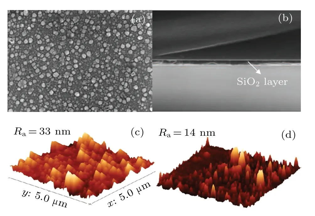
Fig.3.SEM image of(a)10-nm-thick SiO2 layer and(b)cross section of 50-nm-thick SiO2 layer,AFM diagram of(c)bare FINEMET ribbon and(d)FINEMET/SiO2/FePd with 20-nm-thick SiO2 layer.
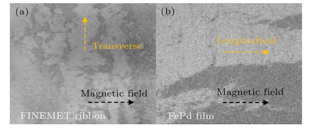
Fig.4.Domain structure of (a) FINEMET ribbon and (b) FINEMET/FePd composite ribbons.
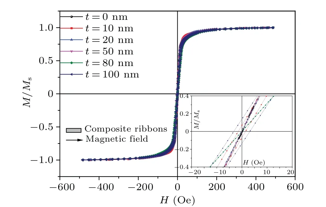
Fig.5.Hysteresis loops of FINEMET/SiO2/FePd composite ribbons with different SiO2 thicknesses, with inset showing partial enlarged view of hysteresis loops.
Figure 6 displays the magneto-impedance curves of the FINEMET ribbon and FINEMET/SiO2/FePd composite ribbons with different SiO2layer thicknesses.All GMI curves exhibit double-peak characteristics, implying that each sample has a preferential transverse magnetic structure.The maximum GMI ratio first increases and then decreases with the increase of the SiO2layer thickness.Therefore, only the appropriate thickness of the SiO2layer can improve the GMI.Based on the analysis of the experimental results, for the FINEMET/SiO2/FePd composite ribbons, the FePd film and the SiO2layer constitute two capacitors,CFePdandCSi, respectively.When AC passes through the composite ribbons,the value ofCFePdpotentially changes due to changes in the magnetic permeability with the external field.Hence, the interaction between the two capacitors produces the best insulator thickness.It can be seen from Fig.6(a) that the GMI curves of the FINEMET/FePd composite ribbons show asymmetrical characteristics.However,the GMI curves of the bare FINEMET ribbon are symmetrical.[18]Because the FINEMET ribbon and FePd film have different magnetic structures, the FePd film with the longitudinal structure generates a bias field(Hb)on the FINEMET ribbon.The generation mechanism of theHbis the dipole–dipole interactions between the FePd film and the FINEMET ribbon.The dipole–dipole field between FePd film and FINEMET ribbon can be represented asHdipand calculated as follows:
wheremFePdandKare the magnetic moment of FePd film and geometric factor,respectively.The geometric factorKdepends on the material size and the distance between FINEMET ribbons and FePd film,and is inversely proportional to the distance.
To further investigate the magnetic dipole interactions with the increase of the SiO2layer thickness, the magnetoimpedance curves at a frequency of 1.4 MHz are shown in Fig.7(a).The magnetic field corresponding to the minimum value of the magnetic impedance in the weak field has a particular offset value(∆H)towards the right side with respect to the zero field.The ∆Hgradually decreases with the increase of the SiO2thickness.The magnetic dipole interaction between the FePd film and the FINEMET ribbon lead to the decrease of the peak field(Hp)presented in the magneto-impedance curve.TheHpdecreases gradually with the increase of SiO2layer thickness.The curves of ∆Hwith different SiO2layer thicknesses are shown in Fig.7(b).When the thickness of SiO2layer is 10 nm, ∆His 0.6 Oe.When the thickness of SiO2increases to 100 nm,∆Hdecreases to 0.1 Oe.It suggests that SiO2thickness can affect the value ofHdip.Hdipdecreases with the decrease of the geometry factor and the increase of SiO2thickness.Therefore,Hdipdominates the peak field of the composite ribbons.
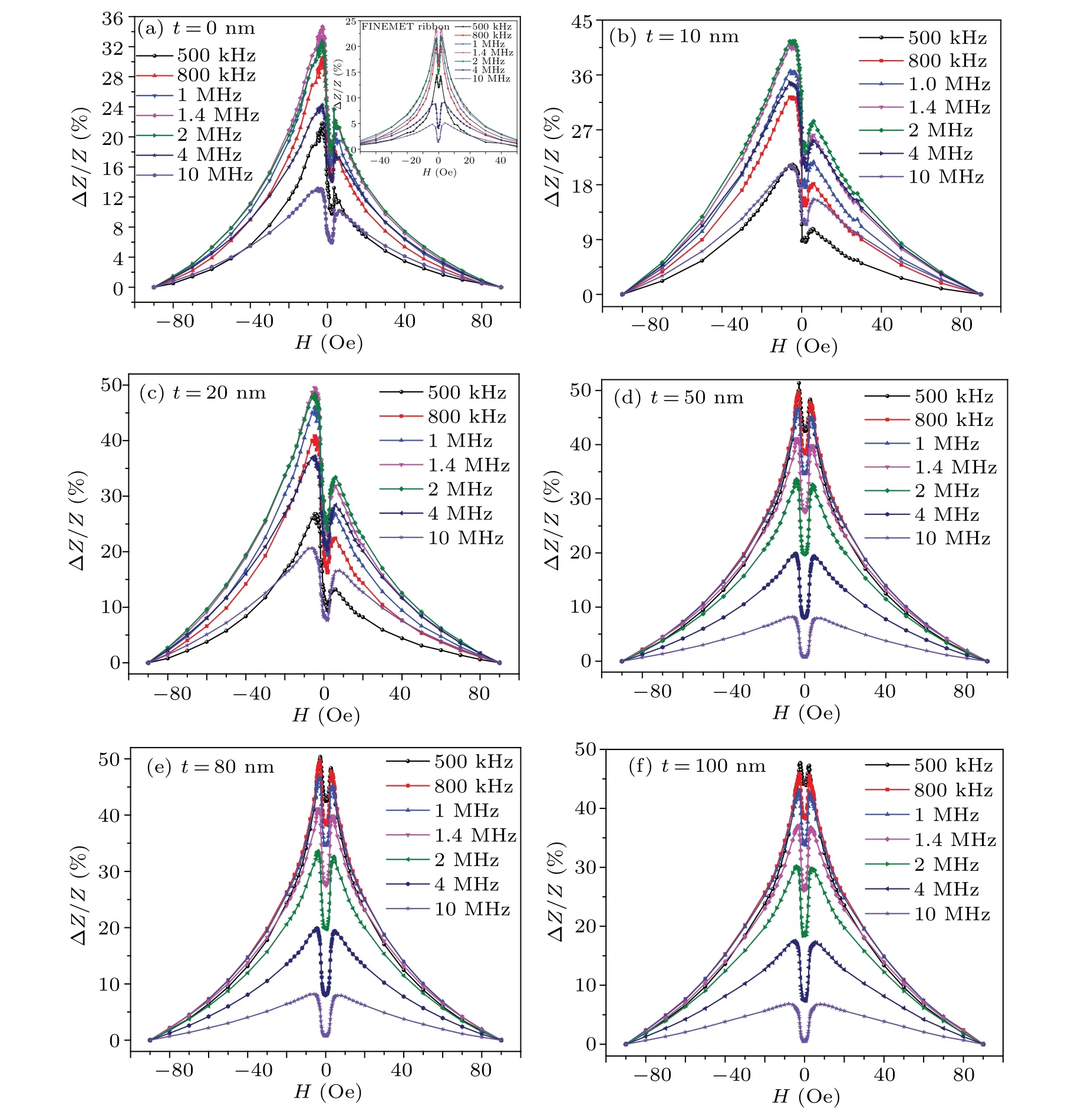
Fig.6.GMI curves of FINEMET/SiO2/FePd composite ribbons with different SiO2 layer thicknesses.

Fig.7.(a)Magnetic impedance curves of FINEMET/SiO2/FePd composite ribbons with different SiO2 layer thicknesses at f =1.4 MHz and(b)∆H curve with the thickness of SiO2 layer.
Figure 8 shows the relationship betweenHdipand peak field (∆Hp) in the FINEMET/SiO2/FePd composite ribbons.It can be seen that the offset ∆H=Hdipof the magnetoimpedance curves for the composite ribbons, and ∆Hpis approximately equal toH.The ∆Hpalmost coincides with the dipole fieldHdip(see Fig.8).It proves that SiO2layer triggers off the magnetic dipole interactions between the FePd film and the FINEMET ribbon.Therefore,Hdipaffects the peak field of the magneto-impedance curve.
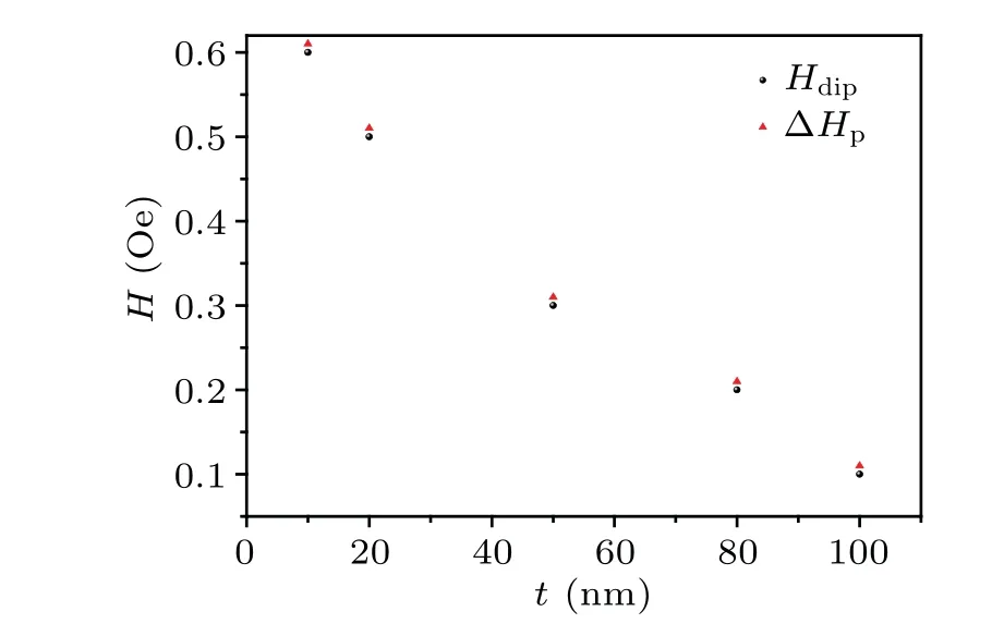
Fig.8.The ∆Hp and Hdip curves with different SiO2 layer thicknesses.
Figure 9(a)shows the GMI ratios of FINEMET/SiO2/FePd composite ribbons with different SiO2layer thicknesses.Figure 9(b) presents the maximum GMI ratio (GMImax) and the characteristic frequency (fmax) varying with the thickness of the SiO2layer.Thefmaxis a significant frequency when the GMI ratio is maximum.The GMI ratio reaches a maximum value at the characteristic frequency and then decreases with the frequency increasing.When the frequency is low,the skin effect is weak, and the external magnetic field is insufficient to produce a large change of the MI ratio.As the frequency gradually increases, domain wall motion and magnetization rotation contribute to the dynamic transverse permeability,thus increasing the GMI ratio.When the frequency further increases, the damping of eddy current is enhanced, and the transverse permeability decreases, resulting in a decrease of GMI ratio.From Fig.9(b), it can be seen that the maximum GMI ratio first increases and then decreases.The GMI ratio reaches 58% when the SiO2layer thickness is 50 nm.The GMI ratio drops to 47% when the SiO2layer thickness is 100 nm.After SiO2layer is coated, the characteristic frequency of the FINEMET/SiO2/FePd composite ribbons significantly decreases (500 kHz).The characteristic frequency can be roughly estimated as follows:
whereµφis the saturated permeability at a 90-Oe field anddis the thickness of the SiO2/FePd film.The characteristic frequency is related to the magnetic properties and thickness of the coating layer.In this study of composite ribbons,the lowest characteristic frequency is obtained,which provides the possibility for applying composite ribbons to the magnetic sensors.
4.Conclusions
The FINEMET/SiO2/FePd composite ribbons are prepared with various SiO2layer thicknesses.The GMI ratio of FINEMET/SiO2/FePd reaches 58%, and the characteristic frequency drops to 500 kHz with the increase of SiO2layer thickness.The MOKE confirms that FePd film and FINEMET ribbon have different domain structures.The FePd film with the longitudinal domain structure produces a bias field on the FINEMET ribbon, resulting in the asymmetry of the GMI curve.The dipole–dipole model is established and used to explain the mechanism of the bias field with the thickness of the SiO2layer.The results show that the dipole–dipole interactions play a significant role in tuning the asymmetric giant magneto-impedance.The research results provide a promising method of developing sensitive components based on the linear AGMI,which can be applied to magnetic sensors.
Acknowledgements
Project supported by the Natural Science Foundation of Shandong Province, China (Grant No.ZR2022MF276),the Major Innovation Fund of Qilu University of Technology (Shandong Academy of Science), China (Grant No.2022JBZ02-02), the Fund from Shanghai Science and Technology Commission, China (Grant No.22142200900),and the Natural Science Foundation of Guangxi Zhuang Autonomous Region,China(Grant No.2019GXNSFAA245056).
杂志排行
Chinese Physics B的其它文章
- Interaction solutions and localized waves to the(2+1)-dimensional Hirota–Satsuma–Ito equation with variable coefficient
- Soliton propagation for a coupled Schr¨odinger equation describing Rossby waves
- Angle robust transmitted plasmonic colors with different surroundings utilizing localized surface plasmon resonance
- Rapid stabilization of stochastic quantum systems in a unified framework
- An improved ISR-WV rumor propagation model based on multichannels with time delay and pulse vaccination
- Quantum homomorphic broadcast multi-signature based on homomorphic aggregation
