Structural Analysis and Life Prediction of Thrust Chambers For Hydrogen-Oxygen Rocket Engines
2023-03-30LIUXiaoLIYongjiangWUYouliangZHAOShihongTIANYuanSUNBing
LIU Xiao ,LI Yongjiang ,WU Youliang ,ZHAO Shihong ,TIAN Yuan ,SUN Bing
1 Beijing Aerospace Propulsion Institute,Beijing 100076
2 School of Astronautics,Beihang University,Beijing 100191
Abstract: After several trial runs,penetrating cracks appeared in the thrust chamber wall of a hydrogen-oxygen rocket engine,which will affect the service life and performance of the engine.It is necessary to reduce the wall heat flux by injection element mixture ratio biasing or propellant films to prolong the life of the liner wall.In this paper,the deformation of three types of inner walls was calculated under cyclic mechanical loading,and the stress-strain response and the fatigue life of the inner walls were compared.The results show that the bottom midpoint of the gas side channel,with the largest residual strain,is the most prone to failure.In addition,the adoption of injection element mixture ratio biasing or film cooling can greatly increase the life of the inner wall,and the improvement effect of the two measures is similar.
Key words: thrust chamber,cracks,heat transfer,fatigue life
1 INTRODUCTION
After several trial runs,penetrating cracks appeared in the thrust chamber inner walls of a hydrogen-oxygen rocket engine,which would affect the service life and performance of the engine.Hence,reasonable and effective thermal protection measures should be adopted.Due to the high pressure and high heat flux of the combustion chamber,the thermal protection of the inner walls requires not only hydrogen regeneration cooling,film cooling,and an improved heat insulation coating,but also reducing the mixing ratio of the side zone.For example,Vulcain 2,J-2,SSME,LE-7,and RD-0120 adopt gas film cooling,while J-2,LE-7 and RD-0120 all adopt injection element mixture ratio biasing[1-2].It is certain that reducing the gas wall temperature or reducing the temperature difference between the gas and liquid wall would be an effective measure to reduce the high-temperature creep and improve the low cycle fatigue life.A great deal of research has been done on the deformation and life of thrust chambers both at home and abroad[3-9],mainly focusing on the analysis of channel structures,inner wall materials,coating thickness and so on.When the pressure drops,the materials and processing capacity of channels are limited,while injection element mixture ratio biasing and film cooling are effective measures to restrain cracking,thereby improving the cycle life of inner walls.However,the analysis of the injection element mixture ratio biasing and film cooling has mainly focused on their effects on combustion and heat transfer of thrust chambers,the effects on the nonlinear deformation and fatigue life have rarely been analyzed[10-12].
This paper compares the nonlinear deformation and fatigue life of the inner wall using three methods: structures adding injection element mixture ratio biasing,or film cooling and the original structure,respectively.The effectiveness of different structures on the life of thrust chambers was analyzed.
2 PHYSICAL MODELS AND COMPUTATIONAL METHODS
2.1 Physical Models
In this paper,we cover the structural analysis and life prediction of the thrust chamber body using three structures.This includes the original scheme (i.e.only using the regenerative cooling,Case A),adding injection element mixture ratio biasing scheme (Case B),and adding the film cooling scheme (Case C).The injection element mixture ratio biasing and film cooling in the side region mainly reduce the gas wall heat flux by secondary cooling on the gas side wall surface.Case B makes the mixing ratio of the injection elements in the border area lower than that of the central injection elements by adjusting the structure of the outermost injection elements.Case C uses hydrogen from the thrust chamber head to cool the thrust chamber wall.
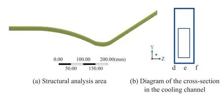
Figure1 Structural analysis area and cooling channel section
Due to the periodicity of the thrust chamber structure and its loading,the wall region of the single cooling channel,corresponding to the maximum circumferential temperature and heat flux,was selected for the analysis,as shown in Figure 1.Figure 1 (b) is a schematic diagram of the cross-section of the cooling channel.To determine the position where the first failure occurred on the section,three high-risk points on the gas side of the inner wall shown in the diagram (i.e.point d,e,f) were analyzed.
According to the operational process of the rocket engine,the calculation was divided into four phases: pre-cooling,hot run,post-cooling,and relaxation.In the pre-cooling phase,the wall temperature was 30 K and the coolant side pressure was 0.4 MPa.During the hot run phase,the temperature of the chamber wall,the pressure distribution of the coolant and the hot gas obtained from the fluid-thermal coupled analysis were taken as the boundary conditions of thermal load and mechanical load for the analysis of the chamber wall deformation.In the post-cooling phase,the temperature was 120 K and the pressure load was 0.2 MPa.
2.2 Computational Methods
Nonlinear finite element analysis of the thrust chamber wall structure was carried out by ANSYS Workbench.The Von-Mises yield criterion was adopted,and the dynamic strengthening criterion was used to define the change of the subsequent yield surface after the material entered plastic deformation.
The total strain was broken into three parts using the elastoplastic finite element method,as shown in Equation (1).

whereεis the total strain vector,εelis the elastic strain vector,εplis the plastic strain vector,andεthis the thermal strain vector.When the material enters plastic deformation,the strain increment is broken into two parts: the elastic increment and the plastic increment,as shown in Equation (2).The law of strain evolution satisfies the description of Equation (3):
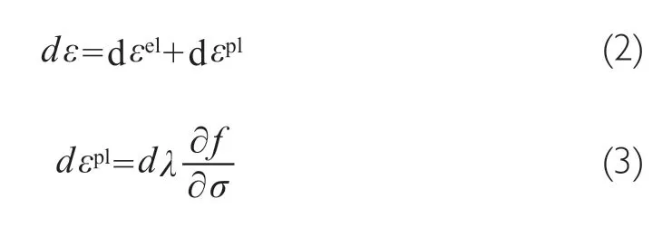
wheredλis the plastic strain increment amplitude,fis the yield surface equation andσis the stress vector.The constitutive equation based on the Von-Mises yield criterion was adopted:

wheresis the deviatoric stress tensor and theαis the back stress tensor,which is superimposed by three back stress tensors.As shown in Equation (5),σyis the size of the yield surface.The law of evolution of dynamic back stress tensors is controlled by Equation (6).

whereCiandγiare material parameters.
3 STRUCTURAL ANALYSIS
The structural analysis of the thrust chamber includes single-cycle analysis and multi-cycle analysis.After a complete cycle,there will be some residual strains at the bottom of the cooling channel of the thrust chamber.The stress-strain changes in the four processes need to be analyzed within a single cycle.The residual strain at the bottom of the channel will accumulate in the thrust chamber after several trial runs,so it is necessary to analyze the deformation after multiple cycles of loading.
3.1 Single-cycle Analysis
The results of the three schemes in a single cycle have roughly the same trend,so the stress and strain of the typical cross-section of Case A were analyzed.As shown in Figure 2 and Figure 3,the overall temperature of the thrust chamber is reduced from 298 K to 30 K in the pre-cooling phase.As the temperature of the inner wall changes much faster than that of the outer wall,and the thermal expansion coefficient of the inner wall is higher than that of the outer wall,the inner wall tends to shrink relative to the outer wall.At this point the strain is positive.In the hot run phase,the temperature of the inner wall increases sharply,and the temperature of the outer wall is close to the coolant temperature.Therefore,the inner wall tends to expand,but the expansion of the inner wall is blocked by the outer wall,which leads to compressive stress on the inner wall.At this time,the strain of the inner wall is negative,and the compressive strain of the center of the cooling channel is smaller than that of the center of the rib.In the post-cooling phase,the inner wall shrinks due to the decrease in temperature,so that the gas side wall is subjected to tangential tensile stress.At this time,the stress is positive,the strain distribution on the inner wall of the gas side is not uniform because the gas stops transferring heat to the inner wall of the gas side,and the tension strain appears in the center of the cooling channel,the compressive strain appears in the center of the rib.In the relaxation phase,the mechanical load and the thermal load are unloaded.However,some of the tensile stress in the inner wall is still not completely removed,and some of the strain is still not recovered,so residual tensile strain appears in the center of the cooling channel,while the residual compressive strain appears in the center of the rib and the cooling channel tend to bulge downward.
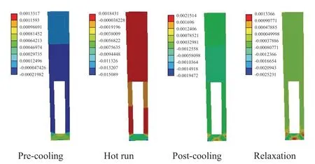
Figure 2 Stress distribution on the cross-section with the maximum temperature of Case A

Figure 3 Strain distribution on the cross-section with the maximum residual strain of Case A
At the end of the cycle,the maximum tensile stress appears at the maximum temperature cross-section of the upstream area of the throat (Figure 2).The maximum residual tensile strain of the different schemes also appears in the upstream area of the throat.For cases B and C,the setting of the low mixing ratio in the near-wall region and the addition of the gas film cause the peak value of the heat flux and temperature of the gas side wall to move downwards to the throat.The maximum residual tensile strain at the end of the single cycle is closer to the throat than that at Case A.Table 1 shows the axial distribution of each section in different schemes.

Table 1 Axial position of the cross-section for each scheme structure
The stress-strain curves of each scheme after one cycle are similar,taking Case A as an example.Figure 4 shows a stressstrain curve with one cycle at each point on the maximum section of residual strain.The strain is positive in tension and negative in compression.It can be seen that after a single cycle,all the points have residual stresses that cannot be completely removed at the end of the single cycle,the size of which is about 150 MPa.The strain at each point in the pre-cooling phase is positive and that in the hot run phase is negative.However,at the end of the post-cooling phase,the strain at point e is positive and the strains at points d and f are negative. Point e is located at the center of the gas side cooling channel.In the pre-cooling phase,the point produces tensile strain caused by the temperature load.While in the hot run phase,the gas side wall surface is directly washed by the high-temperature gas,the wall temperature is much higher than other phases.For the lining material,the higher the temperature is,the lower the yield stress is.At the same time,the tensile stress caused by the pressure load offsets some of the compressive stress caused by the temperature load,so the degree at point e turns backward relative to other points in the hot run phase smaller,thus making the point e appears at higher residual tensile strain,so e-point is the most potential location where the structure will be destroyed first.

Figure 4 Stress-strain history in a single cycle
Figure 5 (b) compares stress-strain at point e of three schemes after a single cycle.It is shown that the residual tensile stress and strain of each scheme are the same after one cycle,and the stress and strain show Case A> Case C> Case B.Due to injection element mixture ratio biasing and film cooling,the heat flux and temperature distribution in the near-wall region are reduced,so the loading conditions of the bottom surface of Case B and Case C channels were better than that of Case A,and the stress and strain were lower than that of Case A at the end of the cycle.
I know that, said the man; your real father was sold at Hamburg last Michaelmas, and your real mother died while calving in spring; but my wife and I have adopted you as our own, and you are our only heir, so you must call me Father
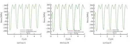
Figure 5 Multi-cycle node stress history
3.2 Multi-cycle Analysis
Figure 5 is the stress history at point e on three key cross-sections (throat cross-section,maximum temperature cross-section,maximum residual strain cross-section) in the fifth cycle.With the increase of the number of cycles,the level of cyclic stress at point e in different cross-sections fluctuates periodically within a fixed range,and the stress fluctuation in the first cycle was not much different from that in the subsequent cycle.Therefore,it is safe to analyze point e.
Figure 6 (a) is the strain history at point e on different cross-sections of Case A in the fifth cycle.The total strain increases steadily with the increase of cycle number,and the strain value at the end of each cycle is larger than that at the end of the previous cycle.In addition,the total amount of strain accumulated at point e on the maximum cross-section of residual strain is larger than that of other cross-sections,which means that the e-point on the maximum cross-section of residual strain is more vulnerable to structural failures than other points and will become the first most probable failure point of the structure.Based on the analysis of single-cycle stress-strain curves,it was found that the most direct cause of the strain accumulation was the excessive tensile strain in the post-cooling phase,which has a large residual amount after the compression strain offset in the hot run phase,and the surplus tensile strain is hardly relaxed during the relaxation phase.Figure 6 (b) shows that the accumulated strain at point e of Case A is significantly larger than that of cases B and C,and the accumulated strain increases with the increase of cycle number.
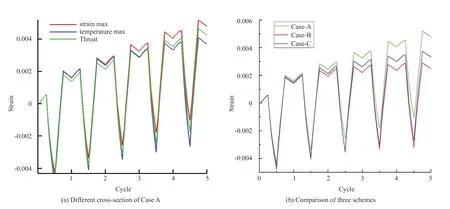
Figure 6 Multi-cycle node strain history
Figure 7 shows the stress-strain evolution at point e on different cross sections in Case A.The stress-strain trajectories of point e on different cross-sections are very similar,and all of them roll forward as the cycles go on,which is the basic characteristic of the typical ratchet effect.After the fifth cycle,the point e stress-strain trajectory on the maximum cross-section of residual strain evolves to a higher degree than that of the other two cross-sections.The e-point of the maximum cross-section of the residual strain gradually presents a more obvious ratchet effect than the point e of the other two cross-sections,respectively
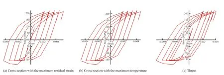
Figure 7 Stress and strain of multi-cycle nodes on different cross-sections of case A
Figure 8 shows the stress-strain evolution trajectory at point e of the maximum residual strain cross-section of the three schemes.It was found that the ratchet effect of Case A is more obvious than that of the other two schemes.Overall,the ratchet effect shows that Case A> Case C> Case B,Case B is relatively safer.
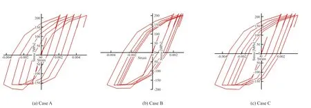
Figure 8 Stress and strain of multi-cycle nodes of different schemes
4 LIFE PREDICTION OF THE THRUST CHAMBER
4.1 Life Prediction Method
The life of the thrust chamber of a hydrogen-oxygen rocket engine is usually in the order of several to dozens of operations,which belongs to the category of a typical low-cycle fatigue problem.The fatigue life of the whole structure depends on the fatigue life at the high-risk point.Therefore,taking into account the two factors of fatigue damageDFand ratchet damageDratcheting,the total damage of a single cycle operation is the combination of two damage factors,as shown in Equation (7).When the total damageDtotalincreases to 1.0,the thrust chamber failure is considered.

For the low-cycle fatigue damage,according to the Manson-Coffin Equation (8),theNFin the equation depends on the magnitude of the cyclic strain,which is obtained from theε-Ncurve,and the Equation (9) is the expression of theε-Ncurve of the material under the high temperature of the engine,where theεtis the stress amplitude value,theσbis the ultimate strength,theEis the elastic modulus,and theεfis the ultimate strain.

Ratchet damage is defined as a function of plastic cumulative tensile strain according to Equation (10),where theεendis the residual strain at the end of the cycle,and theεbegineis the initial strain at the end of the cycle.


4.2 Life Prediction Results
Using the theory of the local strain method,structural failure occurs first at the position where the deformation is the most severe or the number of large load reversals is the greatest,so the service life of the whole structure depends on the life of one or several high-risk points.For the thrust chamber,its service life depends on point e on the maximum residual strain cross-section of the inner wall.Under the basic theoretical framework of the local strain method,the post-processing damage analysis method was adopted for the identified danger points.
Figure 9 shows cumulative fatigue damage,cumulative ratchet damage,and cumulative total damage at point e on the cross-section with the maximum residual strain of three schemes.Both cumulative fatigue damage and cumulative quasi-static damage increase with the increase of cycle numbers,but cumulative total damage is mainly determined by cumulative quasi-static damage,because the majority of damage caused by each cycle is quasi-static damage,while fatigue damage is only a small proportion.Therefore,it can be considered that the structural failure mode at each node is a quasi-static failure rather than a fatigue failure.

Figure 9 Multi-cycle cumulative damage
As the cycles go on,the total damage accumulates and the rate of accumulation increases,which conforms to the relation of a quadratic function.Therefore,a curve can be fitted according to the total damage-cycle number of the first five cycles to predict the subsequent growth of the damage.As can be seen from Figure 10,the cycle life of the three operating conditions is 34,39 and 39,respectively.The life of the thrust chamber can be greatly improved by adding injection element mixture ratio biasing and film cooling structures,and the life of the two schemes is equal.
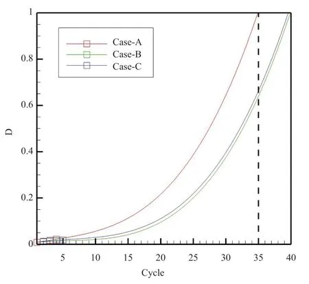
Figure 10 Life prediction of thrust chambers
5 CONCLUSIONS
In this paper,the structure and life of the thrust chamber using three schemes were analyzed,and the conclusions are as follows.
1) The failure mode of the inner wall of the thrust chamber is not the accumulation of residual stress,but the accumulation of strain.The most direct cause of node strain accumulation is that tensile strain in the post-cooling phase is too large,which results in a large residual amount after the compression strain offset in the hot run phase and is not reduced even in the relaxation phase.
2) For the same scheme,the most vulnerable point of structural failure is point e on the maximum cross-section of the residual strain,that is to say,the bottom midpoint of the gas side cooling channel.
3) Because of injection element mixture ratio biasing and film cooling,the heat flux and temperature in the near wall region are obviously reduced.Therefore,under the loading conditions in the channel bottom surface of cases B and C are better than that of case A,and the stress and strain at the end of a single cycle are lower than that of case A.In addition,the accumulated strain of case A is obviously larger than that of cases B and C after multiple cycles,the accumulated strain increases with the increase of cycle number.
4) The service life of the thrust chamber can be greatly improved by injection element mixture ratio biasing and film cooling structures,while the service life of the two schemes is equal.
杂志排行
Aerospace China的其它文章
- Safety Analysis of Launch Vehicle Software Systems
- Cooling Technology for Thrust Chamber of LM-5B LOX/kerosene Engine
- Research on Frequency Improvement for LOX/kerosene Rocket Engine-Servo Loop
- Design of A Hot Redundant Communication Network for Drive Control Systems of Mobile Launch Platforms
- 12-Point Leveling Systems for Mobile Platforms and Emergency Plans
- Dynamic Analysis of Launch Vehicle Piping Systems
