High efficiency of broadband transmissive metasurface terahertz polarization converter
2023-03-13QiangguoZhou周强国YangLi李洋YongzhenLi李永振NiangjuanYao姚娘娟andZhimingHuang黄志明
Qiangguo Zhou(周强国) Yang Li(李洋) Yongzhen Li(李永振)Niangjuan Yao(姚娘娟) and Zhiming Huang(黄志明)
1State Key Laboratory of Infrared Physics,Shanghai Institute of Technical Physics,Chinese Academy of Sciences,Shanghai 200083,China
2Hangzhou Institute for Advanced Study,University of Chinese Academy of Sciences,Hangzhou 310024,China
3Institute of Optoelectronics,Fudan University,Shanghai 200438,China
4University of Chinese Academy of Sciences,Beijing 100049,China
5Key Laboratory of Space Active Opto-Electronics Technology,Shanghai Institute of Technical Physics,
Chinese Academy of Sciences,Shanghai 200083,China
Keywords: terahertz,polarization converter,metasurface,transmittance
1.Introduction
Polarization is an important property of electromagnetic waves,which characterizes the orientation of the electric field intensity vector at a given point in space as a function of time.Polarization is widely used in antennas,[1-3]radars,[4,5]and radio communications,[6]and has become a hot topic research.Traditional polarizers mainly use anisotropic crystals, optically active materials and liquid crystals to control the electromagnetic waves.However, the above methods have disadvantages such as large volume, high loss, narrow response frequency band, and unfavorable integration, which hinder the practical application of electromagnetic wave polarization converters.With the development of science and technology,it has been able to meet the needs of high integration and high energy utilization.[7]In recent years, the emergence of metasurfaces has provided a new way to control the polarization state of electromagnetic waves.In particular, polarization converters based on metasurfaces have the advantages of small size,thin thickness,high conversion efficiency,and flexible structural design.When an electromagnetic wave passes through a metasurface, the electric field component induces the polarization response and the magnetic polarization response, while the magnetic field component induces not only the magnetic polarization response but also the polarization response,i.e.,a cross-coupling effect occurs.When no external constant electric field or constant magnetic field is added,the electromagnetic wave passing through the metasurface will show magnetic polarization rotation and circular dichroism phenomenon.By changing the structure of the metasurface unit, the polarizer can realize different functions, such as linear polarization deflection, circular polarization conversion and elliptical polarization conversion.[8,9]With the continuous breakthroughs in research on metasurfaces, their special material and structural properties, such as low loss, low weight,and flexible structural design, have been widely used in electromagnetic engineering research to achieve electromagnetic properties that traditional materials do not have,such as negative refractive index,negative dielectric constant,and negative magnetic permeability.[10-15]The metasurfaces are artificially designed sub-wavelength structured materials with periodic or non-periodic cell arrangements that can achieve the special electromagnetic properties mentioned above.Based on the above-mentioned excellent electromagnetic properties, metasurfaces can effectively control the distribution of the amplitude and phase of electromagnetic waves, so that the electromagnetic waves passing through the metasurface can undergo abrupt changes in phase and amplitude, and realize the control of the polarization state of electromagnetic waves.[16-18]Therefore,the application of metasurface to polarization conversion can effectively improve the performance of polarization converters.[19-22]
Since conventional polarizers do not have advantageous performance in terms of operating band width and polarization conversion ratio (PCR), we design a transmissive terahertz polarization converter based on a metasurface structure,which not only has broadband conversion characteristics but also has the capability of high conversion efficiency for incident electromagnetic waves.By using a double-layer metal metasurface, the device can convert the incidentXdirection polarized electromagnetic waves toYdirection with high performance, and the PCR reaches a high efficiency of close to 100% at 0.288 THz-1.6 THz.The origin is explained by the electric field intensity, magnetic field intensity, surface current, electric field energy density, and magnetic field energy density distributions of the polarization converter at 1.19 THz and 0.87 THz,respectively.In addition,we analyze the influence of different thickness of silicon dielectric layer and upper surface in the converter, polarized wave incidence angle,as well as metasurface material on the polarization conversion performance ofX-polarized waves by numerical simulation,which provides theoretical guiding for further development of high-performance terahertz polarization converters.
2.Theory
The polarization of electromagnetic waves describes the spatial properties of electromagnetic wave motion.When anXdirection polarized electromagnetic wave is incident on a metasurface terahertz polarizer, the electric fields of the incident and transmitted electromagnetic waves can be expressed respectively as[23-25]
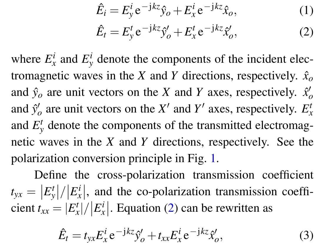

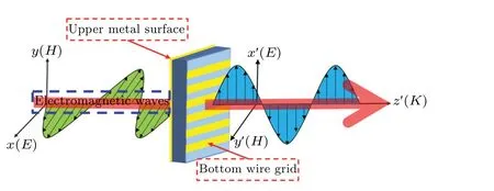
Fig.1.Schematic diagram of terahertz polarization converter.
To measure the conversion capability of the polarization converter,the PCR is defined as[26,27]
To well describe the performance of the designed polarization converter,the transmittance(dB)is defined as
Theyxin the subscript indicates the polarization state of the electromagnetic wave transitions from theXdirection polarization state to theYdirection polarization state.To accurately describe the transmitted wave, the Stokes method is introduced here,defined as[28,29]
whereδ=φy-φxis the phase difference betweentyxandtxx,Iπ/4is the light intensity of the linear polarization component of theπ/4 light wave direction,I-π/4is the light intensity of the linear polarization component of the-π/4 light wave direction,andIRandILare the light intensities of the right and left polarized light components of the light wave,respectively.To describe the linear polarization characteristics of polarized electromagnetic waves, define the polarization rotation angle(PRA)ψand the ellipticity angle(EA)χas[30]
And then get
When the incident electromagnetic wave cause the current distribution between the layers of the multilayer metamaterial structure, or the current distribution of a single metamaterial layer to form a small current loop, it is known from the electromagnetic theory that the small current loop at this time can be equivalent to a magnetic dipole,thereby generating magnetic resonance, and the magnetic moment generated by the magnetic dipole produces a modulating effect on the electromagnetic wave.When the surface current distribution trend of the metasurface device can be equivalent to a current stub, the current stub can be equivalent to an electric dipole,which generates electric resonance,and the electric dipole moment generated by the electric dipole also has a modulating effect on the electromagnetic wave.[31-33]Therefore,the incident electromagnetic wave is incident on the metallic metasurface structure,and the electromagnetic resonance is generated at different frequency points out, and the resulting magnetic moment or electric dipole moment will have a modulating effect on the incident electromagnetic wave,which results in the conversion of the polarized wave.[34-36]
3.Design and analysis
3.1.Structural design and performance analysis
The structure diagram of the broadband transmissive terahertz polarization converter designed in this paper is shown in Fig.2(a).The device consists of a periodic cell structure with a 3-layer design,among which,the upper and lower layers are gold,the intermediate dielectric layer is polyimide,the upper layer is a square-like structure,and the bottom layer is a metal grating structure(see Fig.2(b)).
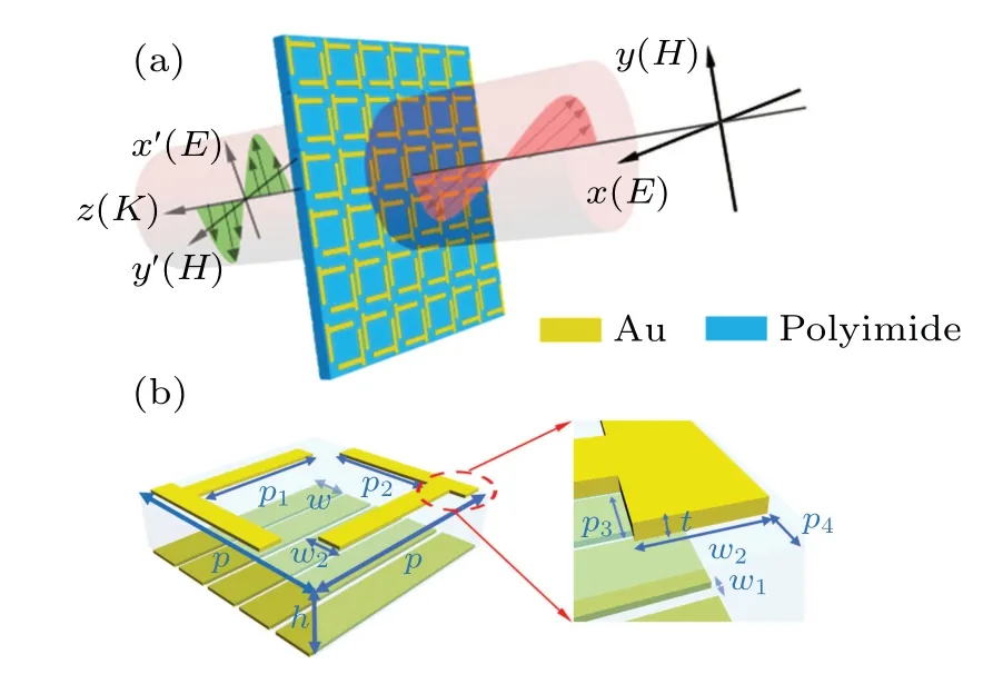
Fig.2.Schematic diagram of the 3D structure of a broadband metasurface terahertz polarization converter.(a)Partially periodic structure of the polarization converter and x-polarization incidence waves,(b)structure of the device cell.
In the periodic cell structure,and the thickness of the upper metal structure ist=0.2µm and the thickness of the lower metal grating ist1=0.3 µm.Based on the finite element algorithm (FEM), the three-dimensional (3D) electromagnetic field simulation of the device is carried out at 0 THz-1.8 THz.In the simulation experiment, the conductivityσof gold is set to 4.56×10⁷S/m, and the relative permittivity of polyimide material is 3.5(1+0.05i).Other structural parameters of the polarization converter areP=100µm,P1=54.5µm,P2= 57.5 µm,P3= 5.5 µm,P4= 3.7 µm,P5= 1.5 µm,h=25µm,W=12.5µm,W1=7.5µm,andW2=7µm.
Fig.3.Cross-polarization (cr-p) and co-polarization (co-p) energy transmission curves.
When the electromagnetic wave withX-ploarized electric field direction is incident perpendicularly to the upper surface of the polarization converter, the structure can realize highefficiency polarization conversion for the polarized wave at 0 THz-1.8 THz.According to Eq.(5), the cross-polarization energy and co-polarization energy transmission curves of this device are simulated(see Fig.3).At 0.54 THz-1.34 THz,the cross-polarization energy transmission is higher than-5 dB,and at 1.19 THz, the maximum is-1.43 dB.To describe the amplitude of cross-polarization signal transmission at different frequency points and the reason of polarization conversion,the surface current, electric field intensity and magnetic field intensity distribution of the polarization converter at 0.87 THz and 1.19 THz are simulated in Fig.4, where 0.87 THz is the frequency point corresponding to the through of crosspolarization transmission coefficient.The surface current defined here is the surface current density(JS), i.e., the product of the surface current density element of the carrier (ρs) and the carrier drift velocity(v),JS=ρsv(A/m).In Figs.4(a)and 4(b),the current distribution on the upper surface of the polarization converter and the bottom surface current show opposite states,implying that the polarization transition at 1.19 THz is generated by the strong magnetic resonance formed between the top and bottom structures, and the magnetic dipole moment generated by the magnetic dipole exerts a modulating effect on the electromagnetic wave.Similarly, it can be seen from Figs.4(c)and 4(d)that the current density on the upper surface at 0.87 THz is smaller than that at 1.19 THz,and it is not obvious that the current distribution on the upper surface and the current distribution on the bottom surface show the opposite state.So,the magnetic resonance at 0.87 THz is smaller than the magnetic resonance at 1.19 THz.From Figs.4(e)and 4(f),it can be seen that the electric field energy is mainly gathered at the endpoints, and the reason is that the endpoints of the fold line and the endpoints of the other fold line form an opening between them,which is equivalent to a capacitor that generates electric field resonance,and the electric dipole produces an electric dipole moment that has a modulating effect on the electromagnetic wave.The magnetic field energy is mainly gathered on the arm of the square ring, which is the arm of the square ring equated to an inductive element that can cause magnetic resonance, and the magnetic dipole generates a magnetic dipole moment that produces a modulating effect on the electromagnetic wave.The electrical resonance and magnetic resonance at 1.19 THz are stronger than those at 0.87 THz,indicating that the polarization conversion capability at 0.87 THz is much smaller than that at 1.19 THz.Therefore, the reason why the metasurface terahertz polarization converter can achieve high-efficiency polarization conversion is mainly due to the regulation effect of the electric dipole moment and the magnetic dipole moment on the electromagnetic wave.[31-33]At 1.8 THz, the cross-polarization and the copolarization energy transmission have a cross point, indicating that the cross-polarization energy and the co-polarization energy transmission are equal.According to Eq.(5),the transmission coefficient(tyxandtxx)and transmittance(t2yxandt2xx)curves of cross-polarization and co-polarization are simulated(see Fig.5).At 1.19 THz, the cross-polarization transmission coefficient reaches the maximum, which is 84.82%.At about 1.8 THz,the cross-polarization transmission coefficient and the co-polarization transmission coefficient are the same,which is 0.05, indicating that the cross-polarization and copolarization voltage signal transmission amplitudes are equal.The cross-polarization transmittance is above 0.6 at 1.11 THz-1.26 THz, and reaches the maximum at 1.19 THz, which is 0.72,indicating that 72%of the incident electromagnetic wave energy is converted to cross-polarized transmission.Therefore, our designed polarization converter has higher energy transfer efficiency than other types of polarization converters, as reported in Refs.[26,27].For the transmittance of the co-polarization, due to the normalized coordinates, it is close to 0.It can be seen from the analysis in Fig.5 that the polarization converter has a high transmittance for converting the incident electromagnetic wave withXpolarization intoYpolarization electromagnetic wave.The transmission of co-polarized electromagnetic waves is very low,that is,the electromagnetic waves polarized in theXdirection are rarely polarized in theXdirection after passing through the polarization converter.In Fig.6, the surface electric field energy density and magnetic field energy density distribution of the polarization converter at 0.87 THz and 1.19 THz are simulated.At 1.19 THz,the surface electric field energy density as well as the magnetic field energy density of the polarization converter are much larger than those at 0.87 THz, indicating that the cross-polarization transmittance at 1.19 THz is much higher than the cross-polarization transmittance at 0.87 THz.Therefore,according to the analysis results of the electric field energy density and the magnetic field energy density on the surface of the polarization converter, it can be known that it is consistent with the results of the transmittance curve.The co-polarization transmittance is basically maintained at about 10-4,indicating that the co-polarization transmittance is very low.At 0 THz-1.8 THz,the maximum co-polarization transmittance is 2.8×10⁻³, which is much smaller than the crosspolarization transmittance.
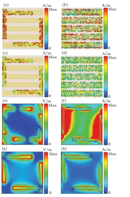
Fig.4.Surface current,electric field intensity and magnetic field intensity distribution of polarization converter at different frequency points,(a)upper surface current distribution at 1.19 THz,(b)bottom surface current distribution at 1.19 THz,(c)upper surface current distribution at 0.87 THz,(d)current distribution on the bottom surface at 0.87 THz,(e)distribution of surface electric field intensity at 1.19 THz,(f)distribution of surface magnetic field intensity at 1.19 THz,(g)distribution of surface electric field intensity at 0.87 THz,(h)surface magnetic field intensity distribution at 0.87 THz.
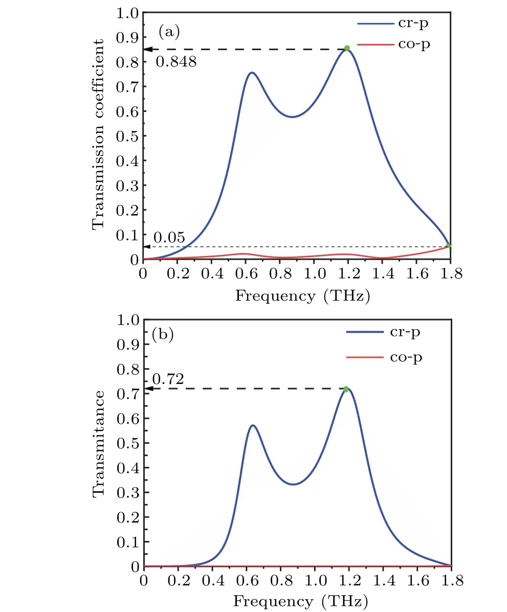
Fig.5.Transmission coefficient (a) and transmittance (b) curves of cross-polarization and co-polarization.
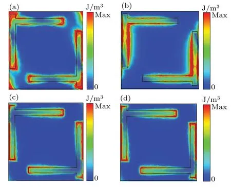
Fig.6.The cross-polarization energy density distribution of the polarization converter at different frequency points, (a) the electric field energy density distribution at 1.19 THz, (b) the magnetic field energy density distribution at 1.19 THz, (c) electric field energy density distribution at 0.87 THz, (d)magnetic field energy density distribution at 0.87 THz.
Figure 7(a) depicts the change curve of the PCR of the device with frequency.At 0.288 THz-1.6 THz, the PCR is higher than 99.9%,that is,more than 99.9%of the energy belongs to cross-polarized transmission.At 0.1 THz-0.288 THz,PCR is still higher than 90%,so it can show that this device is a high-performance linear polarization converter with broadband characteristics.PCR begins to decrease when the frequency is greater than 1.6 THz, and decreases to 0 when the frequency is about 1.8 THz.In addition,in order to further describe the polarization characteristics of the transmitted wave,we give two important performance parameters describing the polarization characteristics of the polarized wave: the PRA(ψ)and EA(χ).Figure 7(b)shows the PRA and EA at 0 THz-1.8 THz.At 0 THz-0.048 THz,the PRA is less than 85°,and at 0.06 THz-1.4 THz, the PRA is close to 90°.At 0 THz-0.531 THz, the EA is greater than 1°, and at 0.036 THz, the EA reaches a maximum of 42.4°.At 0.531 THz-1.49 THz,the EA is less than 1°, showing a polarization state of linear polarization.The above results show that the device has a good linear polarization transmission capability.This means that the polarization converter can perfectly convertX-polarized waves toY-polarized waves in a wide frequency range.

Fig.7.The PCR variation curve with frequency (a), the PRA and EA variation curve with frequency(b).
Through the numerical simulations of the terahertz polarization converter, it can be seen that a Fabry-Perot resonant cavity-like structure is formed between the double-layer metal metasurfaces,and the electromagnetic waves are reflected and transmitted back and forth in the cavity, and the polarization conversion occurs continuously when the electromagnetic waves pass through the metal short cut-offs,which makes the polarization converter obtain a wide operating band and a high cross-polarization conversion efficiency.
3.2.Performance comparison analysis
In order to show that the terahertz polarization converter has a better polarization conversion capability, it is necessary to compare with the performance of other types of terahertz polarization converters(see Table 1).
The first polarization converter is designed by us,and its polarization conversion efficiency is maintained above 99.9%in 0.288-1.6 THz.For the second polarization converter, the PCR is maintained above 50%at 0.53-1.63 THz.For the third polarization converter, its cross polarization with PCR more than 95% in a frequency range of 0.73-1.41 THz.However,in a wide frequency range,the linear polarization transmission capability is not ideal.For the fourth polarization converter,its PCR is above 50%at 0.52-1.82 THz.For the fifth polarization converter, the PCR is maintained above 85% from 0.64 THz to 1.67 THz, and at 0.69 THz, 1.1 THz and 1.57 THz, the PCR~100%.For the last polarization converter, it can be seen from the PCR curve that its polarization conversion efficiency is lower than that of our designed polarization converter.In addition,the linear polarization transmission performance of this device is lower than that of our designed polarization converter.
Therefore,the overall performance of our designed polarization converter exceeds that of other types of terahertz polarization converters by the performance comparison.
4.Discussion
In this section, to provide reasonable research directions and ideas for further improving the performance of terahertz polarization converters,the influence of structural parameters on the performance of terahertz polarization converters will be studied in five aspects of intermediate dielectric layer thickness, intermediate dielectric material, thickness of upper surface,polarization wave incidence angle,and metasurface material.
4.1.Influence of intermediate layer thickness
By setting the dielectric layer thickness (h) as 15 µm,25µm,35µm,45µm,and 55µm,the variation performance of the terahertz polarization converter with the dielectric layer thickness are obtained(see Fig.8).

Fig.8.The relationship between the terahertz polarization conversion performance and the thickness of the medium,(a)transmission coefficient,(b)transmittance,(c)PCR,(d)PRA and EA,the unit of h in the figure isµm.
It can be seen from Figs.8(a) and 8(b) that the crosspolarization and co-polarization transmission in the entire terahertz band change significantly with the change of the thickness of the dielectric layer,indicating that the thickness of the dielectric layer has a great influence on the cross-polarized and co-polarized energy transmission.Table 2 lists the maximum cross-polarization transmission coefficient and transmittance corresponding to different dielectric layer thicknesses.It can be seen that whenh=25 µm, the cross-polarization transmission coefficient and transmittance are the largest.In Fig.8(c), with the thickness of the dielectric layer increase,the frequency points for achieving high PCRs at low frequency bands are different(see Table 3).It shows that appropriate increasing the thickness of the dielectric layer is beneficial to achieve a high PCR in the low frequency range.However, in the high frequency range,the PCR fluctuates greatly with the thickness of the dielectric layer: As the thickness of the dielectric layer increases, the PCR begins to show a downward trend.For example, whenh=25 µm, the PCR appears to decline earlier,and the downward trend is more obvious compared to that ofh=15µm.With the increase of the thickness of the dielectric layer,the PCR begins to show an obvious absorption peak.The larger the thickness of the dielectric layer,the earlier the absorption peak appears, but the PCR at the peak is very low, such ash=45 µm, at 1.7 THz, PCR≈0;h=55 µm, at 1.44 THz, PCR≈0.15.The main reason for the obvious absorption peak is that the thickness of the dielectric layer increases,and the upper and lower layers of the metasurface structure form a structure similar to a resonant cavity.[42-45]When the frequency of the incident electromagnetic wave is just close to the resonant absorption frequency of the resonant cavity,it will produce more obvious energy absorption for the cross-polarized transmission.In Fig.8(d),the PRA and the EA are also sensitive to the change in the thickness of the dielectric layer.With the increase of the thickness of the dielectric layer, the PRA and the EA mainly fluctuate greatly in the high frequency range.Therefore,the greater the thickness of the dielectric layer,the more obvious the fluctuation and the worse the linearly polarized transmission.
By analyzing the effect of different thicknesses of the dielectric layer on the performance of the terahertz polarization converter, it can be seen that the above performance of the polarization conversion of the structure reaches the best whenh=25µm,which also proves that the design of the dielectric substrate thickness of the structure is very reasonable.
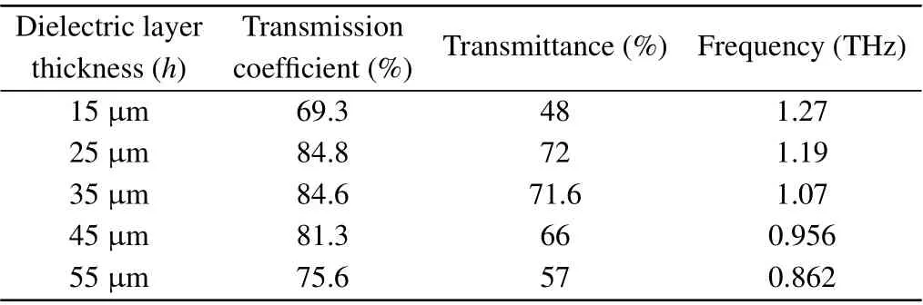
Table 2.Maximum cross-polarization transmission coefficient and transmittance corresponding to different dielectric layer thicknesses.
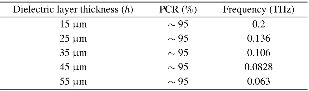
Table 3.The relationship between the thickness of the dielectric layer and PCR.
4.2.Influence of intermediate dielectric material
Based on the analysis in Subsection 4.1,the effect on the performance of the terahertz polarization converter is studied by replacing the intermediate dielectric material by silicon material with a constant thickness ofh=25 µm.The relative permittivity of the silicon material is 11.9, and the conductivityσis 2.5×10⁻⁴S/m.In Figs.9(a) and 9(b),the maximum cross-polarization transmission coefficient and transmittance of silicon material are greater than that of polyimide based material.At 0.67 THz-0.84 THz, the transmittance is higher than 60%, which is greater than the width of the polyimide based material.At 0.7 THz, the transmittance reaches the maximum value of 80.7%, which is 8.7% higher than the maximum transmittance of polyimide.However, the transmission coefficient and transmittance of the silicon-based terahertz polarization converter start to be lower than that of the polyimide based material after 0.74 THz, and the transmittance is close to 0 at about 1 THz.To visually describe the difference in the maximum transmittance and transmission coefficient of cross-polarization at different frequency points using silicon and polyimide based materials, the surface current, electric field intensity, magnetic field intensity, electric field energy density,and magnetic field energy density distribution of the silicon based material at 0.7 THz are presented in Fig.10.From Figs.10(a)and 10(b),it can be seen that the current distribution on the upper surface of the silicon based device at 0.7 THz shows an opposite direction to the current distribution on the bottom layer, implying the strong magnetic resonance formed between the top and bottom structures.The electric field strength at 0.7 THz of silicon based material is lower than that of polyimide based material at 1.19 THz,i.e., the electric field resonance generated is lower than that at 1.19 THz,and the electric dipole moment generated by the electric dipole produces a weaker modulation of the electromagnetic wave than that at 1.19 THz.However, the magnetic field intensity of the silicon based material at 0.7 THz is much higher than the surface magnetic field intensity distribution of the polyimide based material at 1.19 THz,indicating that the magnetic dipole moment generated by the magnetic dipole produces a much higher modulating effect on the electromagnetic wave than that at 1.19 THz, which makes up for the lack of modulating effect of the electric dipole moment on the electromagnetic wave(see Figs.10(c)and 10(d)).Therefore,it can be seen from Figs.10(e)and 10(f)that the electric and magnetic field energies of the silicon based material at 0.7 THz are higher than those of the polyimide based material at 1.19 THz,indicating that the dipole moment generated at 0.7 THz is larger and has a stronger polarization conversion capability.This is in agreement with the performance results of the terahertz polarization converter (see Figs.9(a)and 9(b)).In Fig.9(c), the PCR of silicon based material begins to decrease at around 0.95 THz, and the width of the frequency band with high polarization conversion efficiency(PCR>99%) is significantly smaller than that of polyimide based material.Moreover,when the frequency of the incident electromagnetic wave is greater than 0.95 THz,the PCR curve appears to fluctuate greatly, starting to be lower than that of the polyimide based material,indicating that the silicon based material has poor polarization conversion ability in the high frequency range.In Fig.9(d), the PRA and EA of the silicon based material begin to fluctuate when it is close to about 1 THz,and the linear polarization transmission capability deteriorates at high frequency.
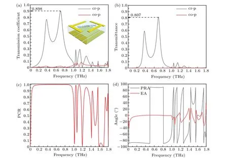
Fig.9.The relationship between the performance of the terahertz polarization converter of the silicon dielectric layer and the frequency,(a)transmission coefficient,(b)transmittance,(c)PCR,(d)PRA and EA.

Fig.10.Current distribution on the upper surface (a), current distribution on the bottom layer (b), electric field intensity (c), magnetic field intensity (d),electric field energy density(e),magnetic field energy density(f)of the terahertz polarization converter with dielectric layer of silicon material at 0.7 THz.
The above analysis of the terahertz polarization converter performance of silicon based material shows that although PCR, PRA and EA are lower than those of polyimide based material in terms of bandwidth,the transmission capability of cross-polarizzation electromagnetic waves has an obvious advantage at the corresponding frequency point.So,the terahertz polarization converter of silicon based material can be mainly used in terahertz imaging and other aspects,which greatly expands the application range of the terahertz polarization converter of this structure.Therefore, the terahertz polarization converter designed in this paper can not only expand the application direction of the terahertz polarization converter by changing the dielectric layer material,but also prove the rationality of this structure design.
4.3.Influence of upper surface material thickness
By changing the thickness of the metal material on the upper surface, the effect of the upper surface with different thicknesses on the performance of the polarization converter is studied.The upper surface material thickness t is set to be 0.8 µm, 0.6 µm, 0.4 µm, and 0.2 µm, respectively.It can be seen from Fig.11(a) that the cross-polarization and copolarization transmission coefficients change very little with the change of the thickness of the upper surface.In Fig.11(b),the cross-polarized and co-polarized transmittances are also less fluctuating with the thickness of the upper surface.The PCR of the terahertz polarization converter also does not change significantly with the thickness of the upper surface(see Fig.11(c)).For the PRA and EA,it can be seen that there is no obvious fluctuation with the change of the thickness of the upper surface in the whole working band(see Fig.11(d)).This means that the upper surface of different thickness has less influence on the linear polarization transmission characteristics of the device in the whole operating frequency band.Therefore, it can be known from the simulation experiments that the thickness of the upper surface of the polarization converter has little effect on the transmission performance of the polarization converter.The main reason is that since the skin depth of terahertz waves in metals is much smaller than the thickness of the metal, the thickness of the metasurface has little effect on the polarization properties.
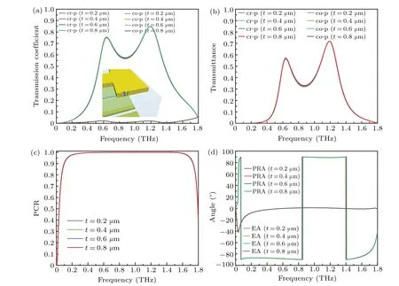
Fig.11.Variation of terahertz polarization conversion performance with the thickness of the upper surface material,(a)transmission coefficient,(b)transmittance,(c)PCR,(d)PRA and EA.
4.4.Influence of the angle of incidence
The effect of different incident angles on the performance of the terahertz polarization converter is studied by varying the incident angleθof the terahertz polarized electromagnetic wave.The incident angleθis set as the angle between the electromagnetic wave incident on theX-Zplane and theZaxis.The incident angles are set to 0°,20°,40°,60°and 80°,and the graphs of the performance of the terahertz polarization converter with the change of the incident angle are shown in Fig.12.
In Figs.12(a)and 12(b),with the incident angle of the polarized wave increasing, the maximum cross-polarization energy transmittance is different (see Table 4).When the incident angle increases from 0°to 40°, the maximum crosspolarization transmittance shows an increasing trend, and when the incident angle continues to increase, the maximum cross-polarization transmittance shows a decrease.As the incident angle of the electromagnetic wave increases, the polarization direction of the incident electromagnetic wave also changes accordingly, and it is no longer the electromagnetic wave in theX-polarization direction, and it cannot match the currently designed terahertz polarization converter.The crosspolarization transmittance in a wider frequency band is lower than the cross-polarization transmittance at 0°incidence.Figure 12(c)shows the PCR at different incident angles.It can be seen that with the increase of the incident angle,the higher the frequency that reaches the high PCR(≈99%),the polarization conversion capability of the polarization converter in the low frequency band is worse, in Table 5.Although when the incident angle deviates from 0°,the PCR produces greater fluctuations in the high frequency range,but the polarization converter can maintain a higher PCR in a wider frequency band.Under different incident angles,the PCR is higher than 99%of the bandwidth(see Table 6).It shows that the polarization converter we designed can meet the practical requirements, and the application prospect is very huge.For the PRA and EA,linear polarization transmission performance deteriorates with increasing incidence angle.In the corresponding frequency band,the PRA deviates from 90°and the EA deviates from 0°(see Fig.12(d)).The reason why the polarization wave incidence angle has a large impact on the performance of the terahertz polarization converter is mainly due to the deviation from theX-polarization direction as the electromagnetic wave incidence angle increases, which does not match the structure of the polarization converter,resulting in poor polarization of the polarized transmitted electromagnetic wave.Therefore, with the incident angle of the polarized wave increases,the performance of the PCR in the low frequency band will be worse.Through the above analysis,the polarization converter we designed has a reasonable structure,excellent performance,and can maintain a high polarization conversion capability in a wide range of incident angles,which greatly expands the scope of practical applications.
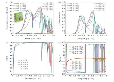
Fig.12.The relationship between the terahertz polarization conversion performance and the incident angle, (a) transmission coefficient,(b)transmittance,(c)PCR,(d)PRA and EA.

Table 4.Maximum cross-polarization transmittance under different incident angles.

Table 5.The relationship between different incident angles and PCR.
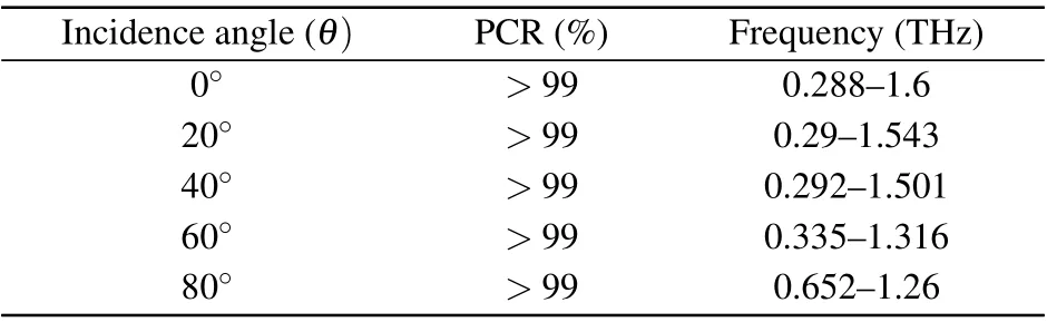
Table 6.The frequency bandwidth of PCR above 99%under different incident angles.
4.5.Influence of metasurface material
In this section, changing the metasurface material, we study its influence on the performance of the terahertz polarization converter.The relevant parameters of different metasurface materials are shown in Table 7,and the other structural parameters remain unchanged.Figure 13 presents the simulated performance curves of terahertz polarization converters with different metasurface materials.It can be seen that the overall performance of the terahertz polarization converters for different metamaterials does not have large fluctuations and the relationship curves are basically consistent,which also shows that our designed terahertz polarization converter structure can maintain good polarization conversion performance for different kinds of metasurface materials.Although the polarization conversion performance of different metasurface materials is basically the same, it is necessary to analyze the polarization conversion performance of different metasurface materials in detail and find out the specific influencing factors to provide basic theoretical guidance for further improving the performance of terahertz polarization converters.
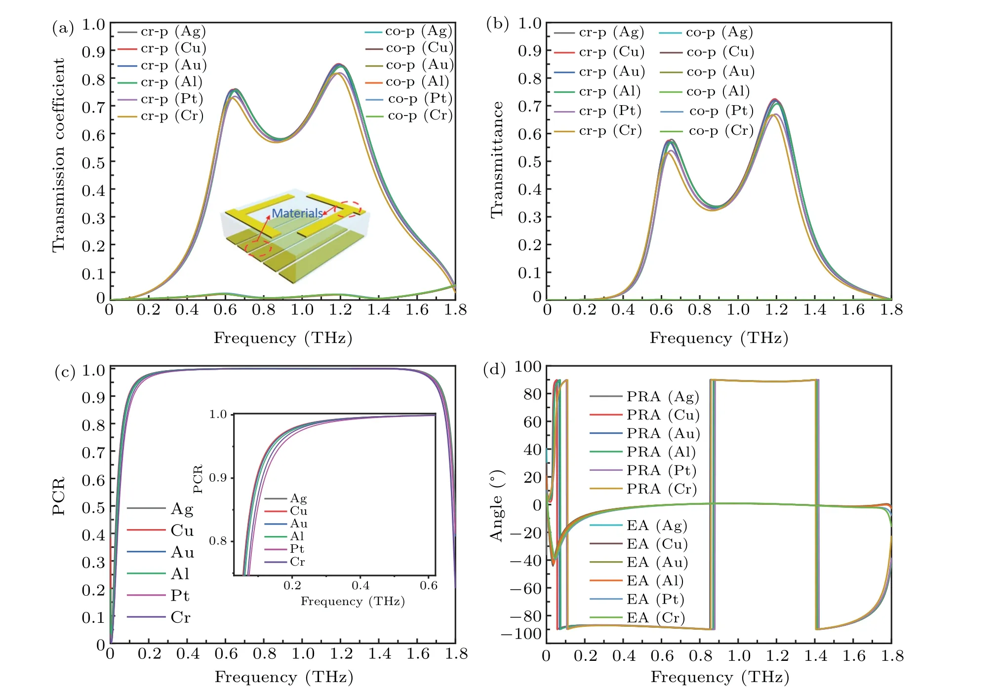
Fig.13.Variation of terahertz polarization converter performance with frequency for different metasurface materials.(a) The transmission coefficient,(b)transmittance,(c)PCR,(d)PRA and EA.
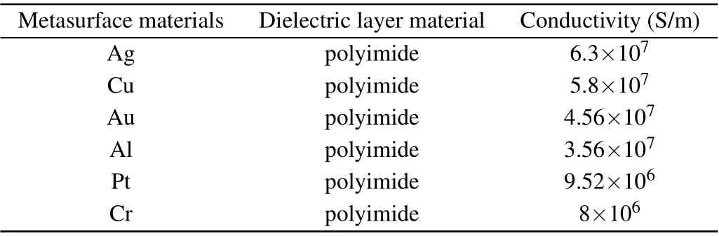
Table 7.Relevant parameters of different metasurface materials.
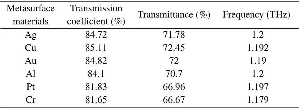
Table 8.The highest cross-polarization transmission coefficient and transmittance of the polarization converters with different metasurface materials.
In Figs.13(a)and 13(b),it can be visualized from Table 8 that the highest cross-polarization energy transmittance and transmission coefficient of terahertz polarization converters with different metasurface materials differ, mainly due to the different electrical conductivity(resistivity)of the metasurface materials.In Tables 7 and 8,the greater the conductivity of the metasurface material, the higher the cross-polarization transmittance and transmittance coefficient in general, mainly due to the higher conductivity, higher carrier mobility and higher energy transfer capability.Figure 13(c)shows that the PCR of the terahertz polarization converters with different metamaterials have the same polarization conversion performance in the high frequency band, but there are differences in the low frequency band,mainly in the frequency points where high PCRs(>99%)are achieved in the low frequency band(see Table 9).The reason for this result is that the resonant cavity structure formed by different metasurface materials has different effects on electromagnetic waves of different frequency bands.The description of the polarization wave characteristics is shown in Fig.13(d),from which it can be seen that the terahertz polarization converters with different metasurface materials have basically the same performance for polarization wave conversion (i.e., linearly polarized transmission), but there are differences in the terahertz polarization characteristics in the low frequency band, and the main difference lies in the different frequency points for achieving high polarization characteristics(see Table 10).The main reason for this result is that the resonator-like structures formed by different metasurface materials have different effects on electromagnetic waves.
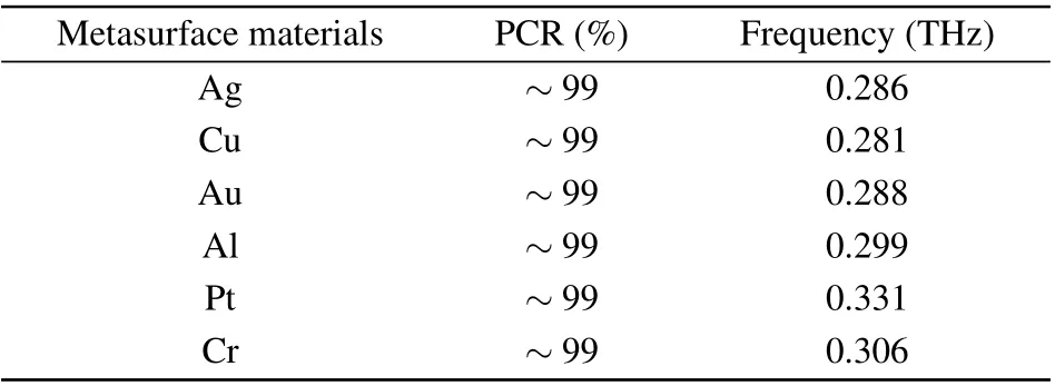
Table 9.The PCR of the terahertz polarization converter with different metasurface materials.

Table 10.The PRA and EA of terahertz polarization converters with different metasurface materials.
In this part, the effects of different structural parameters on the performance of the polarization converter are comprehensively analyzed in five aspects: intermediate dielectric layer thickness, intermediate dielectric layer material, upper metasurface material thickness, polarization wave incidence angle,and metasurface material.For Subsections 4.1-4.4 the rationality of the designed structure is proved, which greatly improves the feasibility of practical applications.In Subsection 4.5,it is shown that this structure can show good polarization conversion performance for different kinds of metamaterials, which indicates that this structure has a broad practical application prospect and great development potential.Moreover, it can be seen from simulation experiments that metals with large metasurface conductivity have higher carrier mobility and better energy transfer capability for terahertz polarization waves,so for terahertz polarization converters based on metal metasurfaces,metallic materials with high conductivity are usually selected.
5.Summary
In summary, an efficient broadband transmission type metasurface terahertz polarization converter is designed by using 3D structure with an upper surface of ruler-like rectangular, an intermediate dielectric layer and a lower surface of metal grid wires.The cross polarization with PCR of the device can be maintained above 99.9% at 0.288-1.6 THz.At 0.06-1.4 THz,PRA~90°,and at 0.531-1.49 THz,EA~0°,which means that the device has good linear polarization transmission characteristics in a wide frequency band.The origin of the high efficiency polarization conversion has been explained by the electric field intensity, magnetic field intensity,surface current,electric field energy density and magnetic field energy density distribution of the polarization converter at 1.19 THz and 0.87 THz, respectively.By further analyzing the thickness of the intermediate dielectric layer, the material of the intermediate dielectric layer, the thickness of the upper surface material, the incident angle of the polarization wave and the metasurface material,the following conclusions can be drawn: (1) The thickness of the dielectric layer has a certain effect on the cross-polarization transmittance of the polarized converter and PCR.Therefore, the thickness of the dielectric layer should be selected for the polarized converter to achieve the best overall performance.(2) The polarization converters of different dielectric layer materials will affect the cross-polarization energy transmission and the working frequency band.For example, when the polarization converter of silicon based material is at 0.7 THz, its transmittance is above 80.7%.The energy transmission performance at this frequency point is very good,and it can be applied to the field of terahertz imaging.(3) The thickness of the upper surface material is generally insensitive to the performance of the polarization converter.The main reason is that the skin depth of terahertz waves in metals is much smaller than the designed metasurface thickness.(4) At 0.652 THz-1.26 THz, the incident angle of electromagnetic wave is in the range of 0°-80°, and its PCR can be maintained above 99%.However,with the incident angle of the polarized wave changes,it is no longer an electromagnetic wave polarized in theXdirection in the strict sense, and the polarization conversion performance of the polarization converter will have a certain impact.(5)Due to the difference of the metasurface material,the conductivity will have a greater impact on the transmittance of incident electromagnetic wave energy.Higher conductivity generally has higher transmission efficiency for incident electromagnetic wave energy,and the performance of the polarization converter is better.
The numerical simulations of the polarization converter shows that the structure of our designed terahertz polarization converter is very reasonable and has great potential for practical applications.For different metasurface materials, the polarization converter has excellent performance over a wide operating band at large incidence angles.For example,to achieve a high PCR and a wide operating bandwidth,the metasurface can be made of the metals with high conductivity,such as Ag and Au.In addition,to further improve the performance of the polarization converter, two-dimensional (2D) materials (such as carbon group elements, transition metal group II sulfides)can be combined to achieve high-performance output of polarized waves.2D materials can not only improve the electrical conductivity of the metal metasurface,but also the Fermi level has the characteristics of easy control,and can realize easy to control high-performance terahertz polarization converters.
The transmission-type terahertz polarization converter designed has a simple structure, small size, low loss, strong polarization conversion ability, excellent polarization conversion performance, good linear polarization property retention and wide operating bandwidth, which will show great practical application value and practical application prospects in optoelectronic devices, analytical chemistry, biology, remote sensing,communication and detection.
Acknowledgements
Project supported by the National Natural Science Fundation (Grant Nos.12134016 and 61625505), Chinese Academy of Sciences (Grant No.ZDBS-LY-JSC025), Sino-Russia International Joint Laboratory of Terahertz Materials and Devices (Grant No.18590750500), and Shanghai Municipal Science and Technology Major Project (Grant No.2019SHZDZX01).
猜你喜欢
杂志排行

Chinese Physics B的其它文章
- Analysis of cut vertex in the control of complex networks
- Atlas of dynamic spectra of fast radio burst FRB 20201124A
- Investigating the characteristic delay time in the leader-follower behavior in children single-file movement
- Micro-mechanism study of the effect of Cd-free buffer layers ZnXO(X =Mg/Sn)on the performance of flexible Cu2ZnSn(S,Se)4 solar cell
- Thermally enhanced photoluminescence and temperature sensing properties of Sc2W3O12:Eu3+phosphors
- Heterogeneous hydration patterns of G-quadruplex DNA