A Precoding Scheme to Reduce the Effect of Channel Correlation for MIMO-PLC System
2023-03-12WangbinCaoHuiKangXiaolinLiangZhiyuanXieXiongwenZhao
Wangbin Cao,Hui Kang,Xiaolin Liang,Zhiyuan Xie,Xiongwen Zhao
1 School of Electrical and Electronic Engineering,North China Electric Power University,Baoding 071000/Beijing 102206,China
2 School of Electronic and Information Engineering,Hebei University,Baoding 071002,China
3 Hebei Key Laboratory of Power Internet of Things Technology(North China Electric Power University),Baoding 071003,China
Abstract: MIMO technique can provide higher information throughput and transmission reliability for the PLC system.However,the MIMO-PLC system based on three-conductor cable has a high correlation among its sub-channels.Spatial multiplexing technology will be affected by the spatial correlation between MIMO-PLC sub-channels.To reduce the system bit error rate caused by MIMO-PLC correlation among sub-channels,this paper proposed a phase rotation precoding scheme for the 2×2 closed-loop MIMO-PLC system.According to the channel transfer function of high correlation MIMO-PLC system,the phase rotation precoding matrix F is calculated,and the transmission signal matrix S is modulated with the F,the code distance at the receiving point with smallest code distance is increased by phase rotation.Simulation results show that the scheme can effectively reduce the bit error rate of the 2×2 MIMO-PLC system based on ML detection,and significantly improve the system performance.
Keywordst: carrier transmission on power lines;telecommunication cables;error correction;precoding
I.INTRODUCTION
Power line communication(PLC)has been widely accepted on account of its wide coverage and low cost[1,2].Due to its advantages,PLC technology has attracted more and more attention in recent years [3—5].Most low-voltage PLC systems based on Single Input Single Output (SISO) technology use phase to neutral coupling and phase to ground coupling for signal transmission.In many countries,however,the majority of modern indoor power networks have three conductors: phase (P),neutral (N),and protective earth (E) [6,7].This three-conductor structure provides conditions for the application of multiple-input multiple-output (MIMO) techniques in PLC systems[8].In recent years,the application of MIMO technology in PLC has attracted a lot of attention.Studies in[9—11]show that MIMO-PLC systems provide higher data rates and larger systems capacity than SISO-PLC systems.However,compared with the wireless communication system,the sub-channels of MIMO-PLC system show higher correlation,which is caused by the electromagnetic coupling in the PLC channel.Specifically,in the traditional transmission three-phase wires,when the voltage in one wire changes,it will cause voltage changes in other adjacent wires under the action of electromagnetic induction [12].This correlation is often detrimental to MIMO communication systems,which limits the system’s capacity.In [13],it has been shown that an increase in channel correlation between the transmit antennas is equivalent to a decrease in signal-to-noise ratio (SNR).Therefore,when the value of the correlation coefficient is close to 1,a higher bit error rate (BER) will be generated.In[14],it has used Cholesky decomposition to decompose the channel matrix of two-input multiple-output system into an independent matrix and a correlation matrix,and eliminated the influence of correlation matrix on the system through the precoding matrix,finally achieving the effect of reducing the BER of the system.However,since the independent matrix’s adjustment effect on the receiver the code distance is not considered,this scheme can only play a limited role in reducing the system error rate.In this paper,aiming at reduce the 2×2 MIMO-PLC system BER,a closedloop precoding scheme based on phase rotation is proposed.In order to obtain a higher data transmission rate,a spatial-multiplexing(SM)technique is used.At the receiver,the signal detection mode is set to maximum likelihood (ML) detection due to its excellent BER performance.Considering decoding complexity,the QPSK modulation scheme is used at the transmitter.At the same time,the Middleton Class A model is selected to simulate the PLC channel noise environment.The main contribution of this paper is proposed a precoding scheme suitable for MIMO-PLC spatial multiplexing system.The scheme mainly reduces the impact of channel correlation on MIMO-PLC system performance by code distance adjustment.Simulation results show that the BER performance of MIMO-PLC system has been effectively improved under the action of the proposed precoding scheme.
The structure of the paper is as follows.Section II presents the MIMO-PLC channel model and the Middleton Class A noise model.Section III analyzes the channel-related characteristics of the three-conductor symmetrical cable in detail,and according to the characteristics,details the scheme of phase rotation and the optimal rotation angle calculation formula.And simulation results and the effect of proposed precoding algorithm on system performance are given in section IV.Finally,conclusions are given in section V.
II.CHANNEL AND NOISE MODEL
2.1 MIMO-PLC Channel Model

Figure 1.Block diagram of MIMO-PLC channel model.
In traditional SISO-PLC systems,differential signals between two wires are usually used to transmit information [15,16].However,the 3-wire structure of the home power line(shown in Figure 1)provides the possibility for the construction of a MIMO-PLC system.Without considering the common mode (CM)signal,the available transmit and receive ports include P-N,N-PE,and P-PE[17].According to Kirchhoff’s law,the sum of the voltage injection of the three ports is zero,and a maximum of two transmit ports and three receive ports can be used without considering the common-mode path[18].Therefore,the MIMO-PLC system model is usually 2×2 or 2×3.In this paper,we choose the 2×2 MIMO-PLC system as our research object,and its channel transfer matrix can be written as
wherehpq(f) represents the complex channel coefficient between thep-th receive port and theq-th transmit port at a frequencyf.In H(f),h11(f)andh22(f)are defined as co-channels,whileh12(f) andh21(f)are defined as cross-channels.In the following,if the frequency is not mentioned,fwill be omitted.The channel capacity formula under this model can be expressed as
where INRis identity matrix,Esis the total energy of the transmitted signal,andNTis the number of transmit ports,σ2mis the variance of the noise.According to the channel capacity formula,the channel capacity of 2×2 MIMO-PLC system and the channel capacity of ordinary SISO-PLC system are shown in Figure 2.It can be found from Figure 2 that the channel capacity of 2×2 MIMO-PLC system has been significantly improved.
After passing through the PLC channel,the received signal model of the 2×2 MIMO-PLC system is
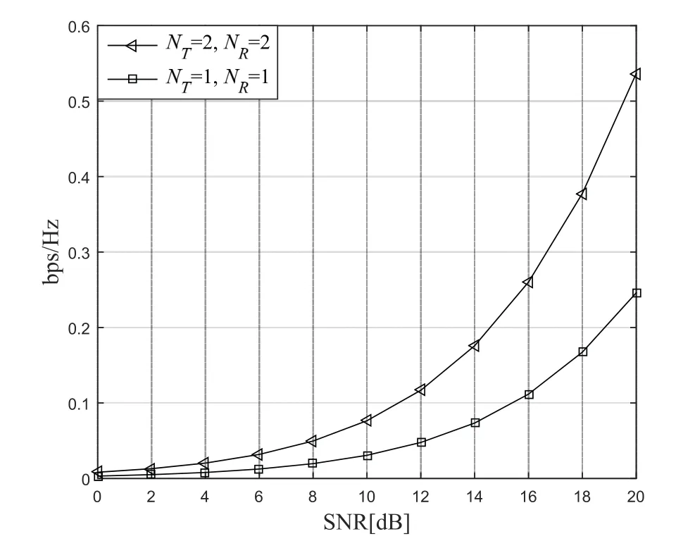
Figure 2.MIMO-PLC and SISO-PLC channel capacity.
where s=[s1,s2]Tis the transmitted signal,r=[r1,r2]Tis the received signal,and n=[n1,n2]Tis channel noise.
2.2 Middleton Class a Noise Model
Noise is an important factor that restricts the quality of power line carrier communication.Compared with wireless communication systems,the noise environment of PLC systems is more complicated.In reference[19],noises in the power line channel are classified into five categories,including colored background noise,narrow-band noise,periodic impulse noise synchronized with the power frequency,asynchronous periodic impulse noise with the power frequency,and random impulse noise.In general,the first three types of noise are classified as background noise because they usually maintain periodic stability,and the latter two types of noise with sharp changes in amplitude are classified as impulsive noise.Previous studies have found that the noise pulse amplitude in PLC channel is at least 10dB higher than the background noise,and even exceeds 50dB in some specific frequency bands[20].In order to get closer to the actual situation,this paper uses the Middleton Class A noise model to simulate the background noise and impulse noise in the PLC system.The model’s probability density expression is
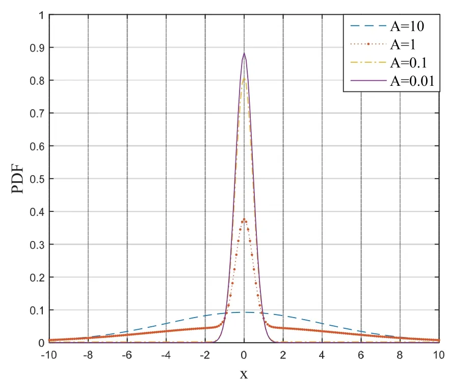
Figure 3.PDF curve of the Middleton Class A noise model when A was different values.
whereσ2mis the variance of them-th noise,σ2Gis the variance of gaussian noise,σ2Iis the variance of impulse noise.γandAare the statistical characteristics of noise.γis the ratio of gaussian noise to impulse noise variance.Ais the pulse characteristic of noise,which is expressed as the product of the average pulse number per unit time and the average pulse duration.According to the actual situation of PLC channel,γvalue is set as 0.01.At this point,the influence of different A values on the probability density function(PDF)distribution of the Middleton Class A noise model is shown in Figure 3.
As can be seen from Figure 3,whenAvalue was large,the Middleton Class A noise was more similar to Gaussian noise.When the value ofAis small,the noise model shows more characteristics of impulse noise.Therefore,in this paper,the value of bothγandAare set to 0.01,which is more in line with the PLC channel situation.
III.CHANNELCORRELATIONAND PHASEROTATIONPRECODING SCHEME
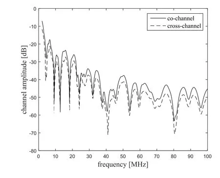
Figure 4.PLC channel transfer functions.
3.1 Correlation Analysis
Generally,due to the symmetry of the three-conductor symmetrical structure of the home power line,crosschannels in a 2×2 MIMO-PLC system maintain a very high correlation,and there is a similar relationship between co-channels.Traditionally,we treat the highly correlated MIMO-PLC channel parameters as follows
whereµejα=hcr/hco,αrepresents the phase angle deviation between co-channels and cross-channels,and its value range is 0≤α ≤2π.µrepresents the modulus ratio of co-channels and cross-channels.Figure 4 shows cross-channel and co-channel transfer functions of MIMO-PLC at different frequencies,which are obtained under the ordinary household experimental environment.It turns out from the experimental data that transfer function of co-channels are significantly stronger than cross-channels,that isµ≤1.
We use the coefficientRto represent the correlation between channel coefficients,and its formula is shown in Eq.(8).
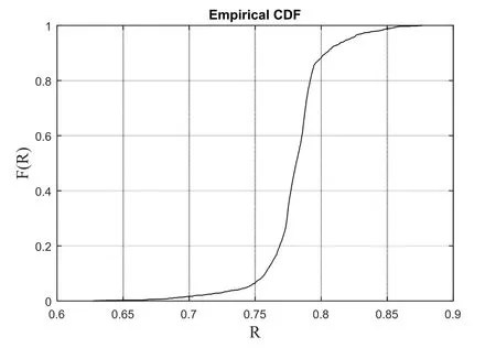
Figure 5.Correlation cumulative distribution function of cross-channel and co-channel.
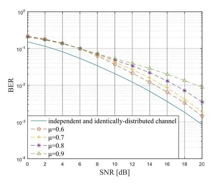
Figure 6.System bit error rate performance at different µvalues.
whereAis the diagonal matrix composed of the eigenvalues of HHH.The cumulative distribution function(CDF) in Figure 5 shows the correlation characteristics of co-channels and cross-channels in the channel model.It can be seen that a high correlation is maintained between channels.
Usually,the channel correlation will directly affect the BER at the receiver.When the receiver uses nonlinear detection,the system BER is directly related to the value ofµ.As shown in Figure 6,the larger the value ofµin the PLC channel condition,the higher the BER of the system.
3.2 Code Distance Allocation Precoding Scheme
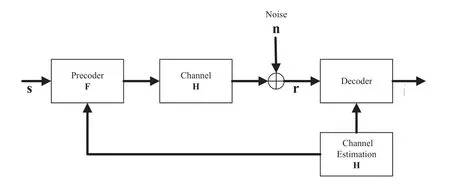
Figure 7.Diagram of closed-loop MIMO-PLC system with precoding.
At present broadband power line communication systems are all using carrier modulation,either based on conventional orthogonal frequency division multiplexing or on Wavelet-OFDM.This adaptation requires in a broad sense channel state information (CSI) at the transmitter.Hence,all current broadband power line communication systems are inherently closedloop[21].Assuming that the channel state H is completely known,the 2×2 spatial multiplexing precoding system is shown in Figure 7,and the vector received by this MIMO-PLC system is
In MIMO systems,receiver sides can consider using different techniques to enhance detection.In the existing technology,the maximum likelihood(ML)detection is an optimum detection method in terms of performance,while facing high complexity[22].Due to the limitation of the number of antennas in the 2×2 MIMO-PLC system,a total of 16 ML measurements are required for ML detection in this paper,and the complexity is acceptable.Therefore,in a MIMO-PLC space multiplexing system,the receiver uses the ML decoding system for signal detection.The final estimated 2×1 signal vectoris
whereCis the constellation set of the QPSK signal.Then the actual sending 2×1 vector is sc,the detectedvalue is sm,and the pairwise error probability(PEP)of sm≠scis
Using the Chernoff boundary formulaQ(x)≤(1/2)exp(−x2/2),we can get
the above formula can be transformed into
whereθis the phase rotation angle,and the adjustment range is [0,π/2].Therefore,designing the best precoding matrix can be transformed to find the bestθvalue.We usedcm(θ) to represent the value of||(sc −sm)||2after the precoding matrix F is adjusted,and the value ofdcm(θ)is as follows
whered1=[(sc1−sm1)+µej(α+θ)(sc2−sm2)]2,d2=[µejα(sc1−sm1)+ejθ(sc2−sm2)]2,d1is the code distance betweensc1andsm1,d2is the code distance betweensc2andsm2.
Figure 8 and Figure 9 show the distance changes of constellation distribution at the receiving terminal before and after processing by the precoding matrix,respectively.The adjustment of precoding matrix on the
code distance at the receiving terminal can be observed intuitively from the figures.The design of precoding matrix is mainly to find a suitableθto maximize the comprehensive code distancedcm_minbetween the signal received under the action of vector F,where
dcm_minis minimum code distance between all error vectors smand the actual transmission vector scwhenθ=0.Its value is a complex function related toµandα.If we define the optimal value of phase rotation of precoding matrix isθopt,and the value ofθoptcan be expressed as
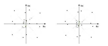
Figure 8.Schematic diagram of the constellation distribution of the receiving terminal before processing by the precoding matrix.
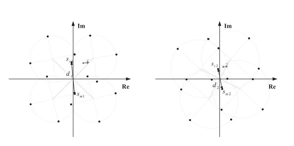
Figure 9.The distribution diagram of the receiving terminal constellation points after processing by the precoding matrix.
In order to facilitate the generation of the precoding matrix,we use a piecewise function pair through the computerθoptvalues are fitted.Theθoptis
where Γ()is a cubic function aboutαandµ,givenby
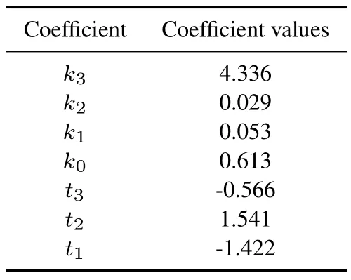
Table 1.The coefficient values in Γ(˘α,µ).
and
The coefficient values in Γ()(three decimal places are retained)are given in Table 1.
Because of theθoptvalue is a function that gradually approachesπ/4.Considering that the complexity of calculating the optimal angleθoptis rather high,in order to reduce the number of calculations at receive ports,we can setθin the precoding matrix to a suboptimal value,that is,θ=θsub=π/4.
IV.SIMULATION RESULTS
In this chapter,we verify the enhancement effect of the phase rotation precoding proposed on the high correlation MIMO-PLC system.As shown in Figure 10,the value ofµin the channel H is fixed,and the rotation angle of the precoding matrix is set to the optimal rotation angleθopt.Under different modulus ratioµvalue conditions,the precoding schemes improve the system performance differently,but all play a role in reducing the system BER.Specifically,since noise power is the main factor that affects BER performance.The SNR is defined as follows
whereEsis the total energy of the transmitted signal,σ2mis the variance of the noise.When the SNR is low,the precoding in this paper does not significantly improve the system performance at this stage.When the SNR is increased to 5dB,the precoding algorithm starts to show performance gains.At the same time,the larger theµvalue,that is,the higher the correlation,the more obvious the precoding scheme is in reducing the bit error rate.The simulation results can prove that the precoding method in this paper can effectively improve the system performance of high channel correlation MIMO-PLC systems.
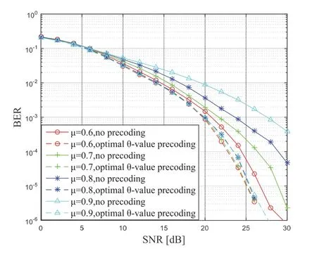
Figure 10.BER performance of the precoding scheme at differentµvalues(QPSK modulation,ML detection).
In order to test the improvement effect of the proposed precoding scheme on the transmission reliability of MIMO-PLC,we carried out simulation verification under the parameters shown in Table 2.In the simulation results shown in Figure 11,we can find that the precoding scheme proposed in this paper has achieved good results.And no matter the optimal precoding rotation angle or the suboptimal precoding rotation angle is taken byθ,this scheme is superior to the Cholesky decomposition scheme proposed in literature [8] in improving the reliability of the system.At the same time,since the suboptimal precoding rotation angleθsubproposed in this paper is only roughly selected as a value ofπ/4,its improvement degree to the system performance is slightly worse than that of the optimal scheme,which is especially obvious when the SNR is higher than 20dB.In addition,because this kind of phase rotation precoding schemes all rely on the adjustment of the minimum code distance at the receiver to reduce the BER,when the signal noise is lower than 6dB,the impulse noise in the PLC will have a decisive impact on the system.Therefore,thescheme proposed in this paper has no obvious effect on the reduction of BER under the condition of low SNR.
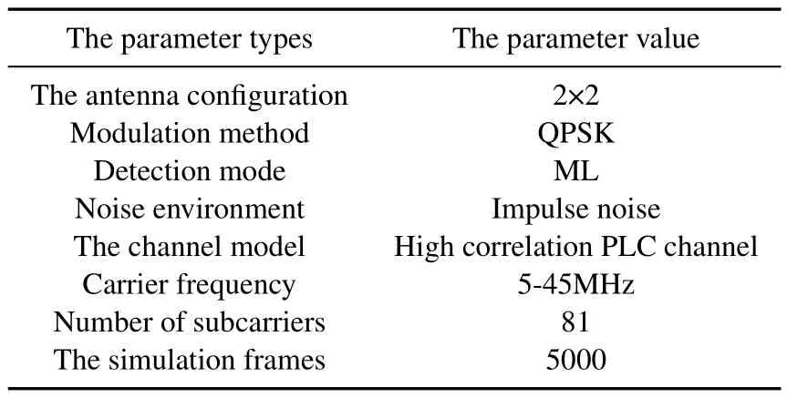
Table 2.Parameters values for simulation.
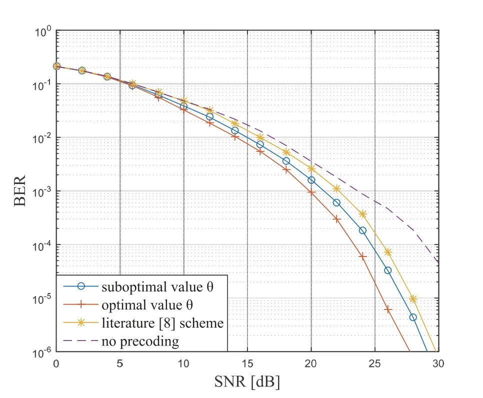
Figure 11.BER performance of different precoding schemes(QPSK modulation,ML detection).
In order to further verify the effect of the precoding scheme proposed in this paper on the performance of the MIMO-PLC spatial multiplexing system,under the same simulation conditions as in Table 2,the MIMO-PLC space under the precoding matrix with the optimal phase rotation angle is processed The multiplexing system and the MIMO-PLC space-time diversity system under the Alamouti space-time block code coding method are compared and simulated.The test results are shown in Figure 12.
From the simulation results,it can be seen that the space-time diversity system using Alamouti code shows excellent BER performance by acquiring the maximum diversity gain of the system.The BER of the space multiplexing system processed by the precoding scheme in the high SNR stage There is still a gap in performance from the space-time diversity system.However,with the improvement of the system SNR,the precoding scheme has gradually enhanced the BER performance of the spatial multiplexing system.When the SNR reaches 25dB,the BER performance of the space-time multiplexing system after precoding is close to In the space-time diversity system.Therefore,it can be considered that when the system noise environment is ideal,the precoding scheme can help the MIMO-PLC spatial multiplexing system with higher transmission rate to achieve the same transmission reliability performance as the MIMO-PLC space-time diversity system under the same conditions.Encoding is obvious and effective in improving the performance of the MIMO-PLC spatial multiplexing system.
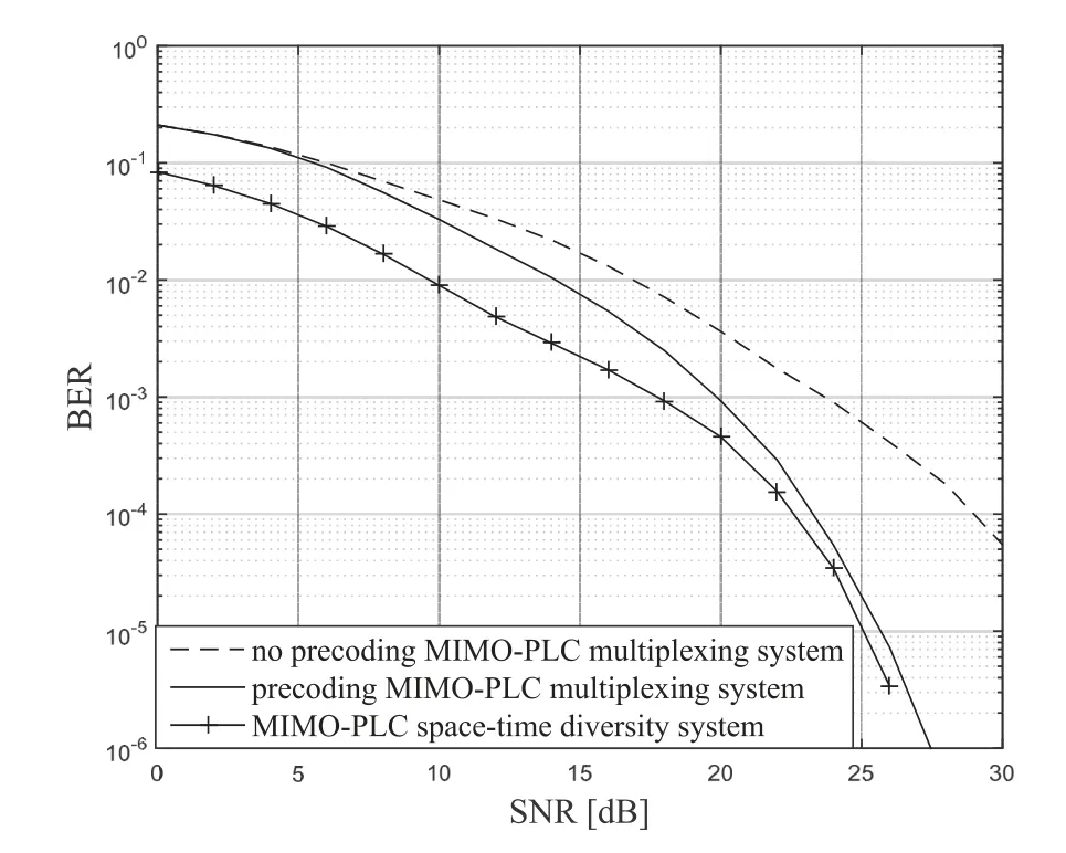
Figure 12.BER performance of Space-time division coding and space multiplexing coding(QPSK modulation,ML detection).
V.CONCLUSION
In this paper,our work mainly includes two aspects.First,we analyzed the related characteristics of the 2×2 MIMO-PLC system built on the three-core symmetric cable and established the relationship between attenuation parameters of each subchannel.a phase rotation precoding scheme is proposed to improve the reliability of the system by adjusting the code distance.The simulation results show that the precoding scheme can significantly reduce the BER and improve system performance.
ACKNOWLEDGEMENT
This work was supported by the National Natural Science Foundation of China (No.62001166),supported by the Natural Science Foundation of Hebei Province of China(E2019502186,F2019201362),and supported by the Fundamental Research Funds for the Central Universities(2021MS073).
杂志排行
China Communications的其它文章
- Convergence of Digital Twin and 6G enabled Edge Intelligence: Theories,Algorithms and Applications
- Design and Implementation of Secure and Reliable Information Interaction Architecture for Digital Twins
- The Development Trends and Research Fronts in Orbital Angular Momentum Technology: A Bibliometric Analysis
- A Dynamic Bayesian-Based Comprehensive Trust Evaluation Model for Dispersed Computing Environment
- Research on Network Cognition Model and Mechanism of Intelligent Information Network
- Low-Density Parity-Check Codes: Highway to Channel Capacity
