追踪锂金属负极的压力与形貌变化
2023-02-17朱迎迎王勇徐淼吴勇民汤卫平朱地何雨石马紫峰李林森
朱迎迎,王勇,徐淼,吴勇民,汤卫平,朱地,何雨石,马紫峰,李林森,2,*
1上海交通大学化学化工学院,变革性分子前沿科学中心,上海 200240
2上海交通大学四川研究院,成都 610213
3上海空间电源研究所,空间电源技术国家重点实验室,上海 200245
4齐鲁工业大学,山东省科学院能源研究所,济南 250014
1 Introduction
Lithium-ion batteries using ultrathin (< 50 μm) lithium (Li)metal anodes (LMBs) promise energy density exceeding 400 Wh·kg-1(800 Wh·L-1) and have attracted significant attention in recent years due to their potential application in consumer electronics and drones1–3. One of the major barriers facing LMBs is its relatively short cycle life (typically < 100–300 cycles versus 2000–5000 cycles for conventional Li-ion cells),which is related to the formation of dendritic and mossy-like Li particles during battery charging4–7. Such high surface-area Li particles are prone to loss via side reactions and easily becomes“dead lithium” as they are electrically isolated by the solidelectrolyte-interface (SEI) layer8,9.
To improve the cycle performance of the LMBs, many approaches have been developed in recent years to promote dendrite-free and compact Li electrodeposition, such as electrolyte engineering (for liquid cells)1,10–13, Li-anode surface modification14–18, three-dimensional current collector design19,20,and using solid-state electrolytes21–23. Besides these “internally functioning” chemical strategies, externally applying pressure against the LMBs can also strongly impact the morphology of the electrochemically deposited Li particles due to the malleable nature of metallic Li and has been shown to improve the cycle performance by several research groups24–29. However, a close inspection of the published results reveals a surprisingly large variation in the applied pressure, ranging from a few PSIs (1 PSI ≈0.0069 MPa) for pouch cells27to tens of MPa for solid-state batteries29. It is unclear how much pressure is sufficient to improve the cycle performance and whether too much pressure would lead to Li electrode deformation. Therefore, it is necessary to understand the relationship between the applied pressure and Li morphological evolution during battery cycling.
It is important to note that the internal pressure of LMBs varies dynamically as metallic Li is deposited or stripped. In order to track the internal pressure change and evaluate the impact of the externally applied pressure on the electrochemical performance, in situ pressure applying-measurement devices(IPAMD) are needed. One such device was recently demonstrated for pouch cells by Louli et al.26, which revealed the pressure evolution during charge and discharge in pouch cells. Compared to the pouch-type cells, coin-type cells are commonly used for LMB research because they are more costeffective and much easier to assemble30. However, in situ pressure measurements for coin cells are rarely reported in literature31. Furthermore, coin cells are often tested under a nonzero pressure applied by various cell holders or clamps, which could vary to some extent among different research groups and present a challenge in data consistency for the LMB research community. Surprisingly, this issue has yet to be examined carefully.
Here we report a custom-designed IPAMD based on thin-film pressure sensors, which can monitor the pressure evolution in coin-type LMBs. We further investigated how externally applied pressure impact the cycle performance of LMBs (LiCoO2cathode versus 50 μm-thick Li anode) in the range of 0-1.7 MPa.Finally, we demonstrated that 5 Ah pouch-type LMBs with a high energy-density over 380 Wh·kg-1could achieve stable cycling over 50 cycles under a medium pressure of ~1.2 MPa.
2 Method
2.1 Preparation of the cathode
The LCO cathode slurry was prepared by mixing 96% (w)LiCoO2(LC-95, Hunan Shanshan), 2% (w) carbon black and 2%(w) PVDF binder in N-methyl pyrolidone. The slurry was subsequently coated on Al foils. The electrodes were calendared to ~60 μm. The mass loading of LCO was ~23 mg·cm-2. The NCA cathode was similarly prepared with the LiNi0.8Co0.15Al0.05O2(BASF TODA Battery Materials LLC Kitakyushu site), carbon black and PVDF at a mass ratio of 94 :3 : 3, the mass loading was 25.80 mg·cm-2. The NCA cathode was punched into rectangular pieces (80 mm × 56 mm) for pouch cell assembly and into disks (10 or 12 mm in diameter) for coin cell assembly.
2.2 Preparation of the Li metal anode
Li foil (50 ± 2 μm-thick lithium film coated on Cu foil) and Li foil (100 ± 2 μm-thick Li metal) were received from China Energy Lithium Co., Ltd. and used without any further treatments. Lithium anode (50 μm-thick) disks were punched with a diameter of 14.5 mm for coin cell assembly. Lithium foil(100 μm-thick) was punched into rectangular pieces (82 mm ×56 mm) in the dry room with dew point lower than -40 °C before pouch cell assembly.
2.3 Cell assembly
The LCO-Li and NCA-Li coin cells were assembled inside an argon-filled glovebox. < 45 μL electrolyte was used for each cell.The 5 Ah-capacity NCA-Li pouch cells were assembled through a layer-by-layer process with the NCA cathode sheets, 100 μmthick Li foil, and Celgard 2325 separators. Ultrasonic welding was used for connection with aluminum (cathode) and nickel(anode) tabs. The number of cathode sheets and Li anode foil was 13 and 14, respectively. 1.0 mol·L-1LiPF6dissolved in FEC/DMC (1 : 1 by volume) with 3% (w) DTD was used as the electrolyte for the pouch cells. The amount of electrolyte was approximately 2.5 g·Ah-1(after the formation cycle at 0.1C and re-sealing). All Li metal pouch cells were assembled in the dry room.
2.4 Electrochemical measurements
Electrochemical tests were carried out using battery cyclers(Shenzhen Neware, BTS4000-5V). The coin cells were cycled inside temperature chambers set at 30 ± 0.5 °C. The LCO-Li were first cycled at 0.1C between 4.5–3.0 V for three cycles and then charged at 0.2C and discharged at 0.5C repeatedly (1C =170 mA·g-1). The NCA-Li cells were cycled between 4.3–2.7 V.The NCA-Li pouch cells was placed between two metal plates,which applied pressure against the pouch cells. The initially applied pressure was 1.6 MPa, which was measured by thin-film pressure sensor. The pouch cells were charged/discharged between 4.3–3 V at 0.1C rate after three formation cycles at 0.1C rate.
2.5 Characterizations
The cycled Li metal anodes were obtained by disassembling the coin cells inside the glovebox and then immediately rinsed with dimethyl carbonate to remove the residual electrolyte and dried under vacuum. SEM characterizations were carried out using a Phenom-Pro scanning electron microscope installed inside an Ar-filled glovebox. The images of samples were taken with an accelerating voltage of 5 kV.
3 Results and discussion
3.1 Pressure measurement for coin cells
We used a flexible thin-film pressure sensor (detection range:0 to 50 kg, ±10% accuracy) to build the IPAMD for the coin cells. The working principle of the thin-film pressure sensor is quite straightforward. The deformation of the sensor element under pressure leads to a change in the electric resistance, which can be conveniently measured using an electrical tester. The custom-designed IPAMD is shown in Fig. 1. We used a G-clamp to apply uniaxial pressure against the coin cell, which was held using a coin-cell holder that had electric contacts on two opposite sides. The applied pressure could be tuned by adjusting the bolt to fasten or loose. Two stainless steel cylinders and three silicone rubber discs were used to ensure uniform contact, which was critical to obtain consistent results. The IPAMD worked in the fixed-displacement mode and enabled real-time tracking of the pressure change caused by the LMB coin cells. We note that the thin-film pressure sensor can also be used to measure the pressure change in pouch cells as well.

Fig. 1 The in situ pressure applying-measurement device.
3.2 In situ pressure measurements for LMB coin cells
We used the IPAMD to investigate the pressure evolution of a LMB coin cell containing a high areal-capacity LiCoO2cathode (~4.2 mAh·cm-2in areal capacity) and thin Li metal anode (50 μm in thickness, ~10.3 mAh·cm-2in areal capacity).The cell was first charged and discharged at 0.1C (1C =3.7 mA·cm-2) for three cycles and then switched to 0.2C charge/0.5C discharge cycling (Fig. 2a). The G-clamp was fastened to provide an initial pressure of ~0.92 MPa. Upon cycling, the stack pressure change coincided with the charging and discharging processes. Nevertheless, an upward trend in stack pressure was observed as the cycle number increased. The pressure change can be rationalized by examining the crosssection of the Li anodes after cycling through scanning electron microscopy (SEM). Fig. 2b shows the cross-section of the original Li anode, in which the original 50 μm-thick Li film and the underlying copper current collector could be clearly differentiated because they had different contrast under the SEM. During charging, Li ions were extracted from the LiCoO2cathode and electrochemically plated onto the Li anode (Fig. 2c),which led to the pressure increase. When the battery was discharged, the deposited Li film was electrochemically stripped(Fig. 2d) and thus the pressure was reduced. After repeated cycling, the Li anode was corroded by side reactions and its total volume expanded (Fig. 2e), which explained the upward trend in the stack pressure. These results proved that our customdesigned IPAMD can monitor the pressure change in LMB coin cells. Because that the volume change of LiCoO2during charge and discharge is quite small (~2%), the observed pressure change could be correlated with the Li anode evolution inside the coin cells. When a different cathode is used (such as sulfur or FeF3),the situation would be quite different.
3.3 Impact of externally applied pressure on LMB cycle performance
We further investigated how the externally applied pressure would impact the cycle performance of LMB coin cells using the IPAMD. The LMB coin cells used a high areal-capacity LiCoO2cathode (~4.2 mAh·cm-2) and thin Li metal anode (50 μm in thickness, ~10.3 mAh·cm-2areal capacity). A liquid electrolyte(1 mol·L-1LiPF6dissolved in 1 : 1 v/v ethylene carbonatedimethyl carbonate, EC-DMC) that is known to be “bad” (i.e.,low Coulombic efficiency)32for Li metal cycling was used in this study. We made this choice to highlight the impact of the applied pressure. We used the IPAMD to apply different initial pressure in the range of 0–1.7 MPa against the LMB coin cells and then cycled the cells at a charging/discharging rate of 0.2C/0.5C. Average results from two cells in each case were shown in Fig. 3. We note that a smaller charging rate is commonly used in LMB research. The coin cells could deliver similar discharge capacities initially (Fig. 3a) but showed different cycle performance (Fig. 3b). Without the externally applied pressure, the cells showed rapid capacity loss (black circles). The cycle performance was only slightly improved at 0.3 MPa (blue circles). It was previously reported that the cycle performance of pouch-type LMBs could be significantly improved by a small pressure of 10 PSI (~0.07 MPa)27.
The higher threshold for the coin-type LMBs may be caused by the disk spring, which was under compression inside the coin cell. We estimate that the disc spring can resist a compression pressure up to ~0.47 MPa (Fig. S1; see photos of the disc spring in Fig. S2, Supporting Information), which may be an approximate lower bound for the externally applied pressure to impact the cycle performance. The improvement of the cycle performance became clear when the initially applied pressure reached 0.6 MPa (green circles) or higher. At 1.4 MPa initial pressure, the cells showed stable cycle performance and a high Coulombic efficiency (CE) of ~99.8% over 110 cycles (red circles in Fig. 3b,c). Interestingly, further increasing the pressure to 1.7 MPa negatively impacted the cycle performance and the CE (Fig. 3c,d). These results suggest that there exists an optimal amount of pressure for improving the cycle performance of the LMBs.

Fig. 2 In situ pressure measurement for lithium-metal coin cells.

Fig. 3 Electrochemical measurements of LiCoO2-Li coin cells tested under pressure.

Fig. 4 SEM characterization of the Li anode after the first charge.
To further understand the relationship between the applied pressure and the cycle performance, we examined the crosssections of the Li anodes after the first deposition (i.e., the first charge process) through SEM. Fig. 4 shows the top and crosssectional views of the Li anodes recovered from the LMB coin cells tested under different amount of initial pressures. Without the applied pressure, a porous Li film made of small-size Li particles was plated onto the Li/Cu anode (Fig. 4a,e). Despite the similar amount of Li-plating capacity (~5.2 mAh·cm-2),increasing the applied pressure to 0.6 MPa (Fig. 4b,f) or 1.5 MPa(Fig. 4c,g) led to a much denser Li film made of larger-size Li particles. Therefore, the active surface area of these two Li anodes should be smaller than the one tested under zero applied pressure, which would effectively reduce side reactions and thus provided a plausible explanation for the improved electrochemical performance.
A surprising observation was made on the Li anode when the initially applied pressure was further increased to 1.7 MPa (Fig.4d,h). The plated Li did not form on the top of the Li anode.Instead, the Li particles grew into the original Li anode and caused significant electrode deformation (Figs. 4h and S3),which may hurt the electrochemical performance as shown in Fig. 3. To the best of our knowledge, such behavior (Li inwardgrowth) has not been reported in the literature of LMB research.This result may have important implications for solid-state batteries as well, which often have a relatively large applied pressure against them22,29.We suggest that the Li inward-growth phenomenon may be explained by the significant size-dependent strength displayed by metallic Li. The Li particles shown in Fig.4d are ~2–4 μm in size. According to previous literature, they could exhibit a yield strength of ~50–75 MPa, a two-orders of magnitude of increase over the bulk strength of Li (0.41–0.89 MPa)33.This explains the observed deformation of the “bulk” Li film in Fig. 4h.

Fig. 5 Pressure applied by the commonly used coin-cell holders or clamps.
3.4 Effect of various coin-cell holders/clamps
In typical electrochemical tests, the LMB coin cells are held either by cell holders or clamps, which exert a certain amount of pressure against the cells. The exact amount of pressure may vary from case to case, which casts doubt on the data consistency because of the pressure effect. To address this concern, we measured the pressure provided by three different clamps and two holders commonly for testing LMB coin cells (Fig. 5). The thin-film pressure sensor was sandwiched between the coin cell and a stainless steel disc during the measurements. None of them could provide a pressure higher than 0.2 MPa. Our studies have shown that the cycle performance of the LMB coin cells were not improved at 0.3 MPa (Fig. 3b). Therefore, it is now safe to conclude that these clamps and holders should not lead to inconsistent results for LMB research.
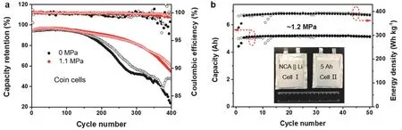
Fig. 6 Electrochemical performance of lithium-metal batteries.
3.5 Long cycle-life LMBs with optimized pressure
We further applied pressure to the LMBs using a “good” (i.e.,high CE for Li anode)32electrolyte, in the hope of further increasing the cycle life of high energy-density LMBs. In this study, we chose to use the 1 mol·L-1LiPF6FEC-DMC + 3% (w)DTD electrolyte (FEC = fluoroethylene carbonate, DTD =ethylene sulfate), which was reported in a previous paper32. This electrolyte is compatible with the high-voltage LiCoO2and lithium nickel cobalt aluminum oxide (LiNi0.8Co0.15Al0.05O2,NCA) cathodes and features an average CE greater than 99.0%.Fig. 6a shows the cycle performance of the LMB coin cells containing a high areal-capacity (~4.7 mAh·cm-2) NCA cathode and a thin Li anode (50 μm in thickness, ~10.3 mAh·cm-2in areal capacity). The cells were cycled at 0.1C for three cycles and then charged and discharged at 0.2C/0.5C between 4.3–2.8 V. The results from two cells were shown in each case. Without the applied pressure, the NCA-Li cells lasted ~240 cycles before losing 20% of capacity (relative to the discharge capacity at the fourth cycle). With a pressure of 1.1 MPa, the cycle life was increased to ~330 cycles (with 80% capacity retention) and the CE was also higher. A smaller stack pressure was used here because the fluorine-containing electrolyte itself promoted dense Li deposition33. The cumulative Li-plating areal-capacity was greater than 1.3 Ah·cm-2, which is among the highest reported for LMBs using a liquid electrolyte and a small amount of Li excess (n/p ratio < 2.2)1,32. Finally, we demonstrated 5 Ah NCALi pouch cells with a high energy-density over 380 Wh·kg-1(Fig.6b). With a pressure of ~1.2 MPa applied by two metal plates(the thin-film pressure sensor was sandwiched between the pouch cell and one of the plate), these pouch cells could achieve stable cycling over 50 cycles and the results from two cells were quite consistent. We expect the cycle life of HE-LMBs may be further improved by means of optimized pressure and better electrolytes.
4 Conclusions
In conclusion, we have developed a custom-designed pressure applying and measurement device to monitor the pressure evolution of LMB coin cells and to understand the relationship between the applied pressure (in the range 0–1.7 MPa) and the electrochemical performance. Similar devices can be made for Swagelok or pouch cells as well using the thin-film pressure sensor. Our results showed that an intermediate pressure is favorable for dense Li deposition and increases the cycle life whereas too much pressure caused Li inward-growth and deformation of the Li anode, which hurt the electrochemical performance of the LMBs. Although these observations were made in the coin cells, they could have important implications for pouch cell and even solid-state batteries, both of which are commonly tested under pressure. The cycle performance of the LMBs was significantly improved in both coin cells (under practically relevant conditions) and in large format, high energydensity pouch cells (5 Ah, >380 Wh·kg-1). It was also confirmed that the commonly used cell holders or clamps for coin cells could only provide a small pressure that is unlikely to exaggerate the cycle performance of the LMB coin cells. However, we do suggest that the electrochemical performance of the LMBs should be reported along with the information on the applied pressure. This research practice will improve the consistency and quality of the reported data in the LMB research community and help unite the efforts to further improve the high energy-density LMBs.
Supporting Information: available free of charge via the internet at http://www.whxb.pku.edu.cn.
References、
(1) Albertus, P.; Babinec, S.; Litzelman, S.; Newman, A. Nat. Energy 2018, 3, 16. doi: 10.1038/s41560-017-0047-2
(2) Zhang, J.-G.; Xu, W.; Henderson, W. A. Lithium Metal Anodes and Rechargeable Lithium Metal Batteries, 2nd ed.; Springer International Publishing: Switzerland, 2017; Vol. 249.
(3) Lin, D.; Liu, Y.; Cui, Y. Nat. Nanotechnol. 2017, 12, 194.doi: 10.1038/nnano.2017.16
(4) Kushima, A.; So, K. P.; Su, C.; Bai, P.; Kuriyama, N.; Maebashi, T.;Fujiwara, Y.; Bazant, M. Z.; Li, J. Nano Energy 2017, 32, 271.doi: 10.1016/j.nanoen.2016.12.001
(5) Bai, P.; Li, J.; Brushett, F. R.; Bazant, M. Z. Energy Environ. Sci.2016, 9, 3221. doi: 10.1039/C6EE01674J
(6) Cheng, X.-B.; Zhang, R.; Zhao, C.-Z.; Zhang, Q. Chem. Rev. 2017,117, 10403. doi: 10.1021/acs.chemrev.7b00115
(7) Hwang, J.-Y.; Park, S.-J.; Yoon, C. S.; Sun, Y.-K. Energy Environ.Sci. 2019, 12, 2174. doi: 10.1039/C9EE00716D
(8) Fang, C.; Li, J.; Zhang, M.; Zhang, Y.; Yang, F.; Lee, J. Z.; Lee, M.H.; Alvarado, J.; Schroeder, M. A.; Yang, Y.; et al. Nature 2019, 572,511. doi: 10.1038/s41586-019-1481-z
(9) Boyle, D. T.; Huang, W.; Wang, H.; Li, Y.; Chen, H.; Yu, Z.; Zhang,W.; Bao, Z.; Cui, Y. Nat. Energy 2021, 6, 487.doi: 10.1038/s41560-021-00787-9
(10) Yan, C.; Yao, Y. X.; Chen, X.; Cheng, X. B.; Zhang, X. Q.; Huang, J.Q.; Zhang, Q. Angew. Chem. Int. Ed. 2018, 57, 14055.doi: 10.1002/anie.201807034
(11) Zhang, X.-Q.; Cheng, X.-B.; Chen, X.; Yan, C.; Zhang, Q. Adv.Funct. Mater. 2017, 27, 1605989. doi: 10.1002/adfm.201605989
(12) Ren, X.; Zhang, Y.; Engelhard, M. H.; Li, Q.; Zhang, J.-G.; Xu, W.ACS Energy Lett. 2018, 3, 14. doi: 10.1021/acsenergylett.7b00982
(13) Chen, S.; Zheng, J.; Mei, D.; Han, K. S.; Engelhard, M. H.; Zhao, W.;Xu, W.; Liu, J.; Zhang, J.-G. Adv. Mater. 2018, 30, 1706102.doi: 10.1002/adma.201706102
(14) Li, N.-W.; Shi, Y.; Yin, Y.-X.; Zeng, X.-X.; Li, J.-Y.; Li, C.-J.; Wan,L.-J.; Wen, R.; Guo, Y.-G. Angew. Chem. Int. Ed. 2018, 57, 1505.doi: 10.1002/anie.201710806
(15) Kim, M. S.; Ryu, J.-H.; Deepika; Lim, Y. R.; Nah, I. W.; Lee, K.-R.;Archer, L. A.; Il Cho, W. Nat. Energy 2018, 3, 889.doi: 10.1038/s41560-018-0237-6
(16) Li, N.-W.; Yin, Y.-X.; Yang, C.-P.; Guo, Y.-G. Adv. Mater. 2016, 28,1853. doi: 10.1002/adma.201504526
(17) Gao, Y.; Yan, Z.; Gray, J. L.; He, X.; Wang, D.; Chen, T.; Huang, Q.;Li, Y. C.; Wang, H.; Kim, S. H.; et al. Nat. Mater. 2019, 18, 384.doi: 10.1038/s41563-019-0305-8
(18) Yu, Z.; Mackanic, D. G.; Michaels, W.; Lee, M.; Pei, A.; Feng, D.;Zhang, Q.; Tsao, Y.; Amanchukwu, C. V.; Yan, X.; et al. Joule 2019,3, 2761. doi: 10.1016/j.joule.2019.07.025
(19) Lin, D.; Liu, Y.; Liang, Z.; Lee, H.-W.; Sun, J.; Wang, H.; Yan, K.;Xie, J.; Cui, Y. Nat. Nanotechnol. 2016, 11, 626.doi: 10.1038/nnano.2016.32
(20) Lin, D.; Liu, Y.; Chen, W.; Zhou, G.; Liu, K.; Dunn, B.; Cui, Y. Nano Lett. 2017, 17, 3731. doi: 10.1021/acs.nanolett.7b01020
(21) Li, J.; Ma, C.; Chi, M.; Liang, C.; Dudney, N. J. Adv. Energy Mater.2015, 5, 1401408. doi: 10.1002/aenm.201401408
(22) Lee, Y.-G.; Fujiki, S.; Jung, C.; Suzuki, N.; Yashiro, N.; Omoda, R.;Ko, D.-S.; Shiratsuchi, T.; Sugimoto, T.; Ryu, S.; et al. Nat. Energy 2020, 5, 299. doi: 10.1038/s41560-020-0575-z
(23) Hu, C.; Shen, Y.; Shen, M.; Liu, X.; Chen, H.; Liu, C.; Kang, T.; Jin,F.; Li, L.; Li, J.; et al. J. Am. Chem. Soc. 2020, 142, 18035.doi: 10.1021/jacs.0c07060
(24) Wilkinson, D. P.; Blom, H.; Brandt, K.; Wainwright, D. J. Power Sources 1991, 36, 517. doi: 10.1016/0378-7753(91)80077-B
(25) Yin, X.; Tang, W.; Jung, I. D.; Phua, K. C.; Adams, S.; Lee, S. W.;Zheng, G. W. Nano Energy 2018, 50, 659.doi: 10.1016/j.nanoen.2018.06.003
(26) Louli, A. J.; Genovese, M.; Weber, R.; Hames, S. G.; Logan, E. R.;Dahn, J. R. J. Electrochem. Soc. 2019, 166, A1291.doi: 10.1149/2.0091908jes
(27) Niu, C.; Lee, H.; Chen, S.; Li, Q.; Du, J.; Xu, W.; Zhang, J. G.;Whittingham, M. S.; Xiao, J.; Liu, J. Nat. Energy 2019, 4, 551.doi: 10.1038/s41560-019-0390-6
(28) Kanamori, S.; Matsumoto, M.; Taminato, S.; Mori, D.; Takeda, Y.;Imanishi, N.; Hah, H. J.; Takeuchi, T. RSC Adv. 2020, 10, 17805.doi: 10.1039/d0ra02788j
(29) Doux, J. M.; Nguyen, H.; Tan, D. H. S.; Banerjee, A.; Wang, X.; Wu,E. A.; Jo, C.; Yang, H.; Meng, Y. S. Adv. Energy Mater. 2020, 10.doi: 10.1002/aenm.201903253
(30) Liu, J.; Bao, Z.; Cui, Y.; Dufek, E. J.; Goodenough, J. B.; Khalifah,P.; Li, Q.; Liaw, B. Y.; Liu, P.; Manthiram, A., et al. Nat. Energy 2019, 4, 180. doi: 10.1038/s41560-019-0338-x
(31) Zhang, C.; Liu, Y.; Jiao, X.; Xiong, S.; Song, J. J. Electrochem. Soc.2019, 166, A3675. doi: 10.1149/2.0581915jes
(32) Zhu, Y.; Pande, V.; Li, L.; Wen, B.; Pan, M. S.; Wang, D.; Ma, Z.-F.;Viswanathan, V.; Chiang, Y.-M. Proc. Natl. Acad. Sci. U. S. A. 2020,117, 27195. doi: 10.1073/pnas.2001923117
(33) Xu, C.; Ahmad, Z.; Aryanfar, A.; Viswanathan, V.; Greer, J. R. Proc.Natl. Acad. Sci. U. S. A. 2017, 114, 57. doi: 10.1073/pnas.1615733114
