Structural integrity evaluation of irradiated LEU targets for the production of molybdenum‑99 using thermo‑mechanical behavior simulation coupled with pressure of fission gas release calculation
2023-01-05MellelMohammediSalhiDougdagMissaouiHanini
N. Mellel · B. Mohammedi · M. Salhi · M. Dougdag · S. Missaoui · S. Hanini
Abstract Irradiated low-enriched uranium as target plates is used to produce, via neutron radiation and from the molybdenum-99 fission product, technetium-99m, which is a radio-element widely used for diagnosis in the field of nuclear medicine. The behavior of this type of target must be known to prevent eventual failures during radiation. The present study aims to assess,via prediction, the thermal—mechanical behavior, physical integrity, and geometric stability of targets under neutron radiation in a nuclear reactor. For this purpose, a numerical simulation using a three-dimensional finite element analysis model was performed to determine the thermal expansion and stress distribution in the target cladding. The neutronic calculation results, target material properties, and cooling parameters of the KAERI research group were used as inputs in our developed model. Thermally induced stress and deflection on the target were calculated using Ansys-Fluent codes, and the temperature profiles, as inputs of this calculation, were obtained from a CFD thermal—hydraulic model. The stress generated, induced by the pressure of fission gas release at the interface of the cladding target, was also estimated using the Redlich—Kwong equation of state. The results obtained using the bonded and unbonded target models considering the effect of the radiation heat combined with a fission gas release rate of approximately 3% show that the predicted thermal stress and deflection values satisfy the structural performance requirement and safety design. It can be presumed that the integrity of the target cladding is maintained under these conditions.
Keywords Irradiated LEU target · Mo-99 production · Integrity evaluation · Thermo-mechanical analyses · Fission gas pressure
1 Introduction
Technetium-99m (Tc-99m) is currently the most commonly used radio-element in nuclear medicine [1]; this pharmaceutical element is produced from the decay of the mother radio-element Molybdenum-99 (Mo-99) which is a fission product of uranium-235. Approximately 95% of Mo-99 is produced by using high-enriched uranium (HEU) targets,generating 40—50 kg of high-level waste annually [2]. The HEU targets and waste produced pose a proliferation risk.To mitigate this risk, many Mo-99 producers around nuclear reactors are undergoing costly renovations of their facilities and techniques to achieve the utilization of low-enriched uranium (LEU) targets [3]. The volume of radioactive waste remains considerable because of the chemical elements that comprise LEU targets [4]. LEU targets have uranium-235 enrichment below 20%, and they consist of aluminum cladding and a core in the form of a U-Al alloy or dispersed fuel UAlx.
The production rate of Mo-99 depends on the thermal neutron cross section of uranium-235, thermal neutron flux at the irradiation position, and half-life of Mo-99. To achieve maximum production of Mo-99, targets are usually irradiated for 5—7 days inside a nuclear reactor under a typical neutron thermal flux of 1 × 10¹⁴n/cm2‧s [5].
The structural integrity of targets under irradiation is of paramount importance from the perspective of nuclear safety and efficient operation of nuclear reactors. The cladding of the target forms the first barrier that prevents the release of radioactive materials into the coolant. Hence, cladding integrity must be ensured under all operating conditions.Moreover, the heat generated in the fuel is removed by the coolant that flows through the available channels between the targets. Under extreme loading conditions, the temperature can reach a maximum value that leads to cladding failure under the effects of thermal—mechanical deflection and contact pressure between the cladding and core. Thus, the structural integrity and cooling of the targets under various operating conditions must be studied numerically and experimentally.
Two criteria, namely the Departure from Nucleate Boiling Ratio (DNBR) and the melting temperature of the cladding, are used to verify the structural integrity of the target under irradiation.
Nevertheless, to take into consideration the fuel melting,stress, and expansion occurring during normal operation,dedicated cladding stress thermal—mechanical calculations can be performed and compared to an adequate criterion that is based on experimental ramp tests.
In this study, thermal—mechanical analysis coupled with fission gas release pressure calculations was performed to evaluate the structural integrity of the target. The properties and parameters of KAERI’s target were used as inputs in these calculations.
For this purpose, the heat generated on the target during irradiation, distributions of thermally induced stress, and deflection was evaluated using commercial CFD Fluent and ANSYS mechanical codes.
As mentioned above, KAERI target properties, configuration, cooling parameters, and neutronic calculation results were adopted as inputs in our developed coupled model.
An analytical approach planned at the MURR research reactor in the USA [6] was also used to evaluate the effect of fission gas release pressure on the thermal—mechanical behavior of the target. The Redlich—Kwong equation of state[7] and the allowable interface gap, which does not influence the thermal contact resistance between the core and cladding of the target, were used to study the effect of gas pressure at the interface.
2 Background
Thermo-mechanical analysis of annular targets and platetype targets for molybdenum production was performed by studying the deflection and stress distribution to evaluate the integrity and probability of LEU target failure. The effects of the boundary conditions, thermal loads, and heat-transfer coefficients on the heat-induced deflection and stress in the targets had been reviewed [8].
Target failure was found to be due to temperature excursion during irradiation and inadequate thermal contact between the uranium foil and the target cladding. It is also due to the presence of microscopic asperities and irregularities at the U-Foil and cladding interface, leading to the formation of gas cavities and solid contact points [9]. Under severe irradiation conditions, where the thermal contact resistance becomes significant, which disturbs heat transfer and leads to the formation of hot spots that result in target failure, the effect of the plate target curvature and the effect of the heat load and heat transfer coefficient on heat-induced deflection and stress were investigated [10]. The structure of the annular target type, with an LEU foil enclosed between two aluminum cylinders, has been studied; the goal was to analyze the target behavior and evaluate the effect of the residual stress with an internal pressure of 36.4 MPa using the code Abaqus. The results showed that the residual stress due to the assembly process tends to compensate for and decrease the peripheral stress in the inner and outer tubes,especially at the end of the irradiation phase [11]. The effects of fission gas pressure release in the gap, uranium swelling, and thermal contact conductance variation on the thermo-mechanical behavior of an annular target containing a low-enriched uranium foil encapsulated in a nickel foil recoil barrier were analyzed. Parametric studies were conducted on the heat generation rate of the LEU target, and the results indicated a satisfactory irradiation performance of the annular target. The results of the analysis showed very small variations in temperature and thermal stress for the analyzed cases [12]. An annular LEU-foil target at MURR was analyzed using ORIGEN 2.0, to estimate the isotopic distribution of gaseous fission products [6]. A 5-g LEU foilbased target with a Ni foil was perforated in a test bench by cutting each of the two welded ends and then splitting the outer tube of the target longitudinally. A fission gas collection system was fabricated and used to collect and count the amount of released fission gas. The results revealed that approximately 0.017% of the expected Xe-133 in the LEU foil was released [13].
3 General description of the model
3.1 LEU plate target and target holder
The neutronic calculation results [14] of the LEU target configuration of the KAERI research reactor and cooling parameters were considered in this application to validate the developed CFD model.
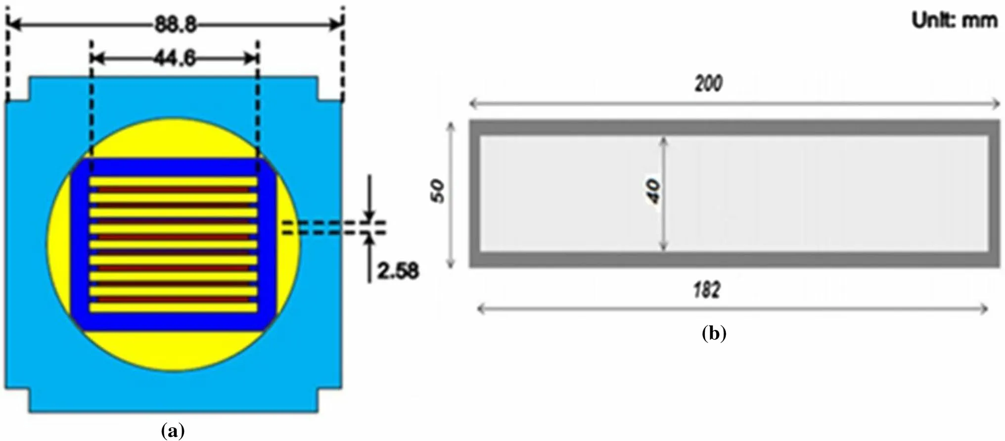
Fig. 1 (Color online) Target holder loaded in the irradiation hole (a), plate target dimensions (b) [14]
The target holder was a rectangular assembly of nucleargrade aluminum (Fig. 1a). It contained eight uranium plates that were vertically parallel to each other. The target plates were positioned in the target holder using clamps in water in an open-pool reactor.
The target plates were constructed of a 6061 aluminum alloy cladding and fuel meat U3Si2-Al (19.75% uranium-235); enrichment of 19.75% was adopted for LEU considering the nonproliferation issue [15]. The dimensions of the plates were as follows: The thickness was 1.58 mm, the width was 50.0 mm, and the length was 200 mm, and they are positioned 2.58 mm apart to create the cooling channels.
The fuel meat had a thickness of 1.58 mm, width of 40.0 mm, and length of 182.0 mm (Fig. 1b). The coolant channel had a width of 44.6 mm and depth of 2.58 mm. The thermal conductivity and specific heat of the cladding were 120 W/m/K and 896 J/kg/K, respectively. The thermal conductivity and specific heat of the fuel meat were 54 W/m/K and 646 J/kg/K, respectively [14] (Tables 1 and 2).
The KAERI targets were irradiated in different irradiation channels of the isotope-production reactor core under a thermal neutron flux of approximately 1014n/cm2s. Thepower generated in each channel was evaluated using the ORIGIN-APR and MCNP codes.

Table 2 Uranium alloy properties [12, 14]
The results of the neutronic calculations revealed that the two plates placed outside the reactor core generate more power than those placed inside, for all three statuses of the core: beginning of cycle (BOC), middle of cycle (MOC), and end of cycle (EOC) [14].
3.2 Thermal hydraulic analysis

Table 1 Aluminum 6061-T6 properties [12, 14]
Table 3 lists the thermal—hydraulic parameters considered in the calculations [10]. Thermal loads corresponding to the three stages of reactor life and cooling conditions were applied to simulate the expected uniform heating and cooling conditions for the target irradiation. The heat loadsconsidered as a volumetric source in the simulation model are, respectively, 4.1 × 10⁹W/m3at the BOC, 3.2 × 10⁹W/m3at the MOC, and 3.08 × 10⁹W/m3at the EOC [10].
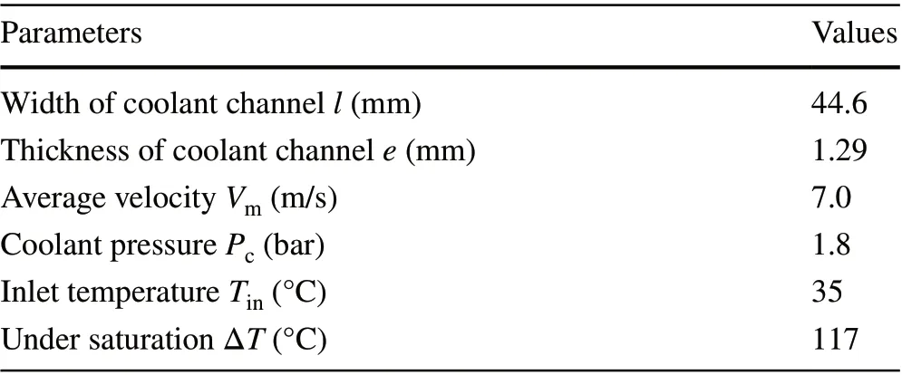
Table 3 Thermal hydraulic conditions
The dimensions and symmetric geometry of the target plate were analyzed using the ANSYS software (Fig. 2).
The results obtained in a previous study [10] showed that the target had a safe minimum nucleate boiling ratio deviation greater than 2 for all three core statuses.
The maximum temperatures achieved at the BOC and EOC were 385.15 K and 363.15 K, respectively, which were below the cladding surface temperature that can initiate nucleate boiling. The maximum temperatures in U-Foil was 428.15 K for the BOC and 394.15 K for the EOC, which are below half the melting temperature of the cladding material considered as the lowest-melting-point material used in the target.
The maximum coolant temperatures at the irradiation channel outlet were 321.15 K for the BOC and 317.15 K for EOC. The results obtained using the CFD numerical model of the irradiated plate target for the three statuses of the KAERI reactor core show that the irradiation thermal performances are acceptable and are approximately close to those obtained using the TMAP code [10].
3.3 Redlich–Kwong model for the FGR pressure calculation
Neutron irradiation of LEU-foil (19.75% uranium-235) generates heat and fission products that include various gaseous isotopes of xenon, krypton, and iodine, in addition to Mo-99.The relative amount of each isotope generated depends on the neutron energy distribution and irradiation duration [6].
Because of the short irradiation time, the majority of the gases will be trapped in the LEU foil, and only 2—3% will escape through the U foil and remain trapped in the space between the U-foil and cladding [16, 17].
As gas accumulates, the fission gas release (FGR) pressure in the gap increases. The resulting force applied in the cladding combines with the thermo-mechanical force,increasing the total force in the aluminum cladding. The most important of the gases released were xenon and krypton, with fission yields of 6.333% and 0.2712%, respectively[18]. Xenon was the main gas that dominated the gap and contributed the most to the FGR pressure.
The model proposed by Redlich and Kwong seems to be the best adapted to calculating the gas pressure within the target, given by the following equation [7]:


Fig. 2 Domain of model simulation [10]
whereTcandPcare the critical temperature and the critical pressure of the elemental fission gas, respectively. A summary of the gas inventories is provided in Table 4.
The relative amount of each isotope generated depends on the neutron energy distribution and irradiation duration.An analysis of the U-foil target placed in theN-1 position at MURR (8 × 10¹³n/cm2s thermal neutron flux) for one irradiation cycle (150 h = 5—7 d) was conducted using ORIGEN2.0 to estimate the total moles/gram of the gaseous fission products in the LEU plate [6].

Table 4 Gas properties and elemental fission gas production from irradiation of U-Foil at MURR
3.4 Internal FGR pressure calculation
Under the assumption that a gap between the U-foil and Alcladding may exist owing to the difference in the coefficient of thermal expansion and the roughness of the surfaces in contact, it is important to identify the magnitude and effect of the internal FGR pressure on the target performance. This gap is assumed to be tolerable when it does not influence the heat transfer; its value is in the order of a few micrometers and depends mainly on the thermal load.
Although released fission gas is a factor influencing variations in the thermal contact conductance, the purpose of this study was to determine only the influence of the amount of FGR pressure on the thermo-mechanical behavior of the target.
In this study, to evaluate the allowable gap with regard to heat transfer and contact resistance, the allowable gap employed for the cases related to the three core statuses of the reactor was taken as 30 µm [19].
To calculate the FGR pressure, four cases related to FGR rates (3%, 6%, 50%, and 100%) were considered. The cases of FGR rates higher than 3% are unrealistic; therefore, they were studied only for illustrative purposes.
A thermo-mechanical model combined with FGR pressure was used in commercial finite element software(ANSYS) to perform the preliminary analysis to study the behavior of the target more realistically.
The calculated gas fission pressure was applied as uniform pressure on the interface surfaces of the target FEM model. The partially constrained boundary condition was considered in this study to reproduce the most realistic target fixation mode (Fig. 3).
The calculation of the FGR pressure was based on the implementation of the Redlich–Kwong model, which requires knowledge of parameters such as the interface temperature, volume, and number of moles of FGR.
The gas volume was calculated by deducting the expanded volume of the cladding from the volume of the irradiated U-foil. The gas temperature was estimated by averaging the temperatures at the interface of the U-foil and cladding under the worst-case heating and cooling conditions for the three different core reactor statuses.
To estimate the number of moles/volume of released gas at the maximum production rate of Mo-99, the LEU foil mass and the data of elemental fission gas production of the LEU target irradiated at MURR were used.
The uranium mass in the LEU plate was calculated as:

Fig. 3 FGR internal pressure application locations and mechanical constraint boundary conditions for LEU target geometry

whereρmis the LEU density of the target;w(U) is the fraction of the weight of uranium in the target; andWm,tm,andLmare the width, thickness, and length of the target,respectively.
The total moles of the FGR (TMFGR) of xenon and krypton were calculated using the following equation:

The pressure values obtained using the target model were in the order of a few kilopascals. For the BOC case and at a FGR rate of 3%, the pressure reached 5.8 kPa. For the MOC case, the pressure was equal to 5.53 kPa. For the EOC case,it was 5.5 kPa.
It should be noted that the lowest pressure occurred when the target was inserted for a few days in the reactor in its EOC state, and it increased when the target was placed in the reactor in the BOC status.
The gas temperature at the interface was estimated by considering the temperature distribution contour in the target at three core statuses by taking the average of the temperatures. The gas temperature obtained was 383.5 K for the BOC, 366 K for the MOC, and 364 K for EOC statuses(Fig. 4).

Fig. 4 (Color online) Temperature distribution contour in LEU target at BOC core status
4 Results and discussion
The goal of the thermo-mechanical behavior preliminary evaluation of the target under irradiation was to prevent LEU target failure and to ensure that no fission products are released to the exterior. This failure is mainly attributed to thermal stress overload, swelling, and fission gas release.Macroscopic uranium swelling was not considered in the present study.
In this study, coupling of the Ansys-Fluent mechanical software and the gas pressure model was used to perform the thermal stress analysis of the irradiated LEU plate. A numerical model was used as a partially supported plate(Fig. 4). Appropriate mesh parameters with a global spacing of 5 × 10⁻⁴m and seven elements on the thickened side of the plate were used. Variations in the thermal conductivities of the U-foil and Al cladding are not significant over the operating temperature range; therefore, in this study, it was assumed to be constant [14, 20].
To ensure that the safety acceptance criteria are met,the induced stress and temperatures in the cladding were maintained below the yield strength and cladding blistering temperature. The obtained results show that the maximum temperature was lower than the cladding blistering temperature limit (673 K) [5, 14].
The effect of the FGR pressure was studied for real cases ranging from 0 to 3%, and it was extended for illustration purposes only for cases with FGR rates varying between specified values 6%, 50%, and 100%.
The monitoring points used to locate the thermal stress and deflection values were located along the top and bottom edges and in the center of the plate cladding, which is considered the first safety barrier (Fig. 5).

Fig. 5 Monitoring points in the plate cladding
Two types of contact linking the U-foil and cladding were considered in the target models; in the first model, the contact regions were assumed to be bonded. In the second model, separation gap formation was considered to simulate the target behavior in extreme cases.
4.1 Case of bonded contact
The contact linking the U-foil to the clad is assumed to be bonded, and it is assumed that the fission gases are located in irregularities that lead to interstitial spaces and solid contact points, where a finite contact pressure exists [6].
To assess the target integrity under irradiation for two FGR rates (0% and 3%), the von Mises stress distribution and deflection during irradiation at three statuses of the reactor core were calculated and compared to their strength limits.
The results of the stress developed in the target for 0%FGR in the BOC case, considered as the most stressed status, are shown in Fig. 6. The red color represents a higher concentration of the thermal von Mises stress, whereas the blue color represents a lower concentration of the equivalent stress that results from coupling uniform heating—cooling conditions.
The von Mises stress contour plot for the upper monitoring point shows that the maximum thermal stress in the plate was 121.53 MPa at the BOC. This maximum equivalent stress was located in the upper part of the target, which corresponded to the coolant outlet. The maximum stress was 98.25 MPa and 95.15 MPa for the MOC and EOC,respectively.
The results displayed in Table 5 indicate that increasing the thermal load increases the von Mises stress, which also confirms that the maximum stress still remains below the allowable stress. For the case when the fission gas rate was 3%, the maximum stress was also located in the upper part of the target.
From the comparison of the stress results above, an increase in stress in the order of a few kilopascals occurred,which was due to the effect of the gas pressure that decreased the heat transfer coefficient of the gap; this, in turn, increased the temperature and consequently increased the stress in the cladding.
The stress values of the state where a release of fission gas occurs and the state where there is no gas release were estimated and are presented in Tables 6, 7 and 8, which show the top, bottom, and center monitoring points as a function of the thermal load. These results confirm that the maximum stress is always lower than the allowable stress even for the FGR rate of 100%.
Table 5 clearly shows that the maximum stress does not exceed the yield strength of the 6061 Al alloy, which is 275 MPa [11], indicating that the target will not fail under the conditions applied. The stress at the monitoring points will not yield at 3% FGR, 6% FGR, and even 100% FGR,and there is a remarkable increase in the stress value with increasing FGR. The 6061 alloy chosen as a cladding material showed a high strength even when the FGR rate reached 100%.
Tables 6, 7 and 8 indicate that increases in the heat load FGR rate will increase the von Mises stress. The highest stress is located at the top corner of the target, which is considered the hottest part of the target. The equivalent stress at the points on the left and right sides of the target was compared to the yield strength and indicated that they exhibit the same behavior as the other surface monitoring points.
Figure 7 shows the deflection profile for a 0% FGR rate for the BOC core status, and the highest deflection was located around the unfixed part, that is, at approximately 0.1 mm, while the lowest deflection was located near the fixed part of the plate.
Table 9 presents the results of the maximum plate deflections for the five FGR cases under the three thermal loadingconditions. The highest deflection of the target was approximately a few tens of microns in three core statuses. This indicates that the lowest deflection occurs when the boundary condition is partially constrained.

Fig. 6 (Color online) von Mises stress profile in the target for 0%FGR rate at BOC core status

Table 5 von Mises stress maximum values at various FGR rates(MPa)

Table 6 Center von Mises stress values (MPa)

Table 7 Top von Mises stress values (MPa)

Table 8 Bottom von Mises stress values (MPa)
Table 9 shows that the deflection increases when the thermal load increases. This trend is consistent with the idea that a higher thermal load induces a greater temperature difference across the aluminum plate and thus augments the thermal expansion difference between the cladding and U-foil.
4.2 Case of the contact region with separation
The separation of the LEU foil from the cladding may result from the FGR pressure and uranium swelling resulting from increased power during a long period of target irradiation;it may also rarely result from a manufacturing defect. When a quantity of fission gas migrates to the gap, the mixture of gases may fill the gap, raise the thermal contact resistance,and influence the mechanical strength of the LEU target,thereby violating the temperature and strength limits.
To examine this case of detachment forming in the contact interface, a stress—deflection analysis was performed using a numerical model of the target and the FGR-controlled pressure. The contact interface was simulated using the concept of contact in the ANSYS Mechanical software.Frictionless-type contact with separation was chosen, the surface-to-surface contact type was selected, and the contact and target surfaces were determined.
The main objective of the deflection analysis based on the FEM approach was to study the separation between the foil and cladding. Separation causes a rise in the thermal contact resistance and thus increases the temperature of the LEU foil, which can lead to probable target failure and cause the fission products to be released in the cooling loop of the reactor.
The results of the deformed target are presented in Figs. 8 and 10. Higher magnification was used to obtain a clear image of the separation contour and target appearance plot after irradiation.
The results show that a large separation was located at the center of the target, which caused a poor transfer of energy through the LEU foil face and probably induced the failure of the target. A small separation was observed at the side locations because of the good cladding fixation in this area,which allowed the energy of the meat to be evacuated, thus preventing target failure in these locations.
The BOC results reveal that the maximum separation was approximately 0.539 mm for the 3% FGR case (Fig. 9).This maximum separation value will not cause any major deformation that could decrease the cooling of the target and cause a local blockage of the cooling channel by cladding expansion (see Fig. 1). The maximum magnitude of separation in the case of a 6% FGR was 1.071 mm (Fig. 9); this may be a worst-case scenario that causes an increase in temperature, inducing an increase in stress, which in turn leads to target failure via the onset of cooling channel blockage.
From the results of the stress distribution analysis in the case of 3% RGF (Fig. 10), it can be seen that the stress concentration occurs mainly in the region connecting the aluminum plate and the LEU foil plate and near the fixed corners of the target structure. Therefore, if a structural failure occurs, it would occur in the stress concentration areas if the stress was greater than the allowable values.
The results indicate that the maximum stress reached 125.72 MPa in the uranium foil, which is still below the admissible stress value and therefore will not induce a fracture. In the case of 6% FGR, the maximum stress was closer to 245.37 MPa in the uranium foil and in the connected region. Therefore, these results show that the stress for FGRless than 6% still meets strength requirements; however, if the FGR is greater than 3%, the safety of the target will be threatened.

Fig. 7 (Color online) Deflection profile of target for 0% FGR rate at BOC status

Table 9 Maximum deflection for 0% of FGR (m)

Figures 11, 12 and 13 show a comparative study of the behavior of the irradiated target under conditions of 3% and 6% FGR rates at the middle, lower, and upper control points for the three reactor core statuses.
A decrease in stresses for 3% and 6% FGR was identified compared to the stress results of the bonded target in the lower and upper locations of the target (Figs. 11, 12 and 13);this decrease was mainly due to the increase in separation,which augments the heat transfer resistance at the contact interface, thus decreasing the thermal transfer between the uranium plate and the cladding.

Fig. 9 Maximum central separation values as a function of thermal load for 3% and 6% FGR
This stress decrease became significant in the case of the BOC and especially in the lower and upper target locations(Figs. 11, 12 and 13); this decrease was mainly due to the fact that the target was relatively well cooled and to the effect of increased separation in these two locations.
Figure 11 shows the expected behavior of the LEU plate cladding separation case at the central location, where an increase in the FGR rate increased the von Mises stress.Under applied cooling conditions and an increase in the FGR rate to 3%, the highest stresses were found at the central points, followed by those at the top and then by those at the bottom of the target.
In the case of the central location, the decrease in stress was not remarkable because a restriction of the cooling channel was created by the expansion of the cladding at this location; thus, the decrease in stress at this location was due solely to the enhanced effect of the thermal contact resistance.
With an increase in the FGR rate above 6%, the contact interface areas and those in the center of the target began to lose their integrity owing to the combined effect of increased contact resistance and the closure of the cooling channel via the cladding expansion.
5 Conclusion
The objective of this study was to evaluate the structural integrity and geometric stability of a low-enriched uranium target during irradiation, by numerically investigating its thermo-mechanical behavior at three thermal loading levels considering the pressure effect of fission gas. A thermomechanical investigation of the target performed in this study using a simplified model to develop more elaborate models that can be validated using experimental results to provide more accurate estimates of the target behavior.

Fig. 10 (Color online) von Mises stress profile for 3% FGR, frontal stress profile (a), lateral stress profile (b)

Fig. 11 Center von Mises stress values as a function of thermal load for various FGR rates
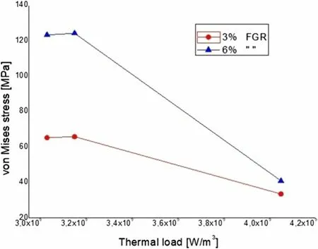
Fig. 12 Lower von Mises stress values as a function of thermal load for various FGR rates
The neutronic calculation results, target material properties, and cooling parameters of the KAERI research group in the field of molybdenum-99 production were used as inputs in our developed model. The results obtained first provide insight into the magnitude of deflection, separation, and stress in the target, which are essentially linear and consistent with the results of other studies.
For the case of a bonded target under irradiation heat combined with a controlled FGR rate, the von Mises stress is greatest at the top control location, followed by the center, and then the bottom one. All the estimated von Mises stresses in the control points were found to be below the yield strength of the cladding alloy. These results also indicate that, under irradiation heat with a controlled FGR rate, the U-foil remains attached to the inner surfaces of the cladding despite the stresses developed and fission gases released. Thus, the integrity of the target plates was retained under irradiation.

Fig. 13 Top von Mises stress values as a function of thermal load for various FGR rates
For an unbonded target under irradiation heat with a controlled FGR rate, a large von Mises stress in the cladding was mainly observed at the interface because of the enhanced mechanical interaction between the U-foil and cladding. The largest separation of cladding from LEU meat was observed at the central location, followed by the upper and lower locations. The results for the unbonded target model combined with a controlled FGR rate indicated that the integrity of the target was threatened once the gas rate reached 6% FGR.
In future research, the model of the LEU target will be extended to the analysis of the thermo-mechanical behavior of the target to take into account the macroscopic swelling of uranium and the effect of fission gases on the thermal contact resistance.
Author contributionsAll authors contributed to the study conception and design. Data collection was performed by all authors; analysis and interpretation of data were performed by N. Mellel and B. Mohammedi. The versions of the manuscript were written by N. Mellel. And all authors commented on previous versions of the manuscript. All authors read and approved the final version of the manuscript to be published.
杂志排行

Nuclear Science and Techniques的其它文章
- Analysis on the influencing factors of radioactive tritium leakage and diffusion from an indoor high‑pressure storage vessel
- A method for neutron-induced gamma spectra decomposition analysis based on Geant4 simulation
- Prediction of nuclear charge density distribution with feedback neural network
- Two‑parameter dynamical scaling analysis of single‑phase natural circulation in a simple rectangular loop based on dilation transformation
- Multiple-models predictions for drip line nuclides in projectile fragmentation of 40,48Ca, 58,64Ni, and 78,86Kr at 140 MeV/u
- A novel approach for feature extraction from a gamma‑ray energy spectrum based on image descriptor transferring for radionuclide identification