Miniaturized time-of-flight neutron spin flipper using a high-TC superconductor
2022-12-20YuChenDongTianHaoWangWolfgangKreuzpaintnerXiaoTaoLiuZeHuiLiYuDongKangJunPeiZhangLongTianChuYiHuangBoBaiXinTong
Yu-Chen Dong• Tian-Hao Wang • Wolfgang Kreuzpaintner •Xiao-Tao Liu • Ze-Hui Li • Yu-Dong Kang • Jun-Pei Zhang • Long Tian •Chu-Yi Huang • Bo Bai • Xin Tong
Abstract A miniaturized neutron spin flipper based on a high-TC superconductor film, developed at the China Spallation Neutron Source(CSNS),is presented.A neutron spin flipper is an essential component for performing polarized neutron experiments and, as such, constitutes a high priority for developing CSNS’s polarized neutron capability. To provide the beamlines with a universal neutron spin flipper operating over a wide wavelength band, the neutron spin flipper utilizes non-adiabatic spin flipping during transit through opposite magnetic fields that are mutually shielded by the superconductor Meissner effect. A compact vacuum heat shield and a low-power consumption sterling refrigerator maintained the superconducting condition while reducing the size and power input of the flipper. The prototype device was tested at the CSNS BL-20, which demonstrated a flipping efficiency of 99% at 4 A°.
Keywords Neutron · Superconductor · Scattering · Spinflipper
1 Introduction
Polarized neutron experiments are an important research area that utilizes neutron scattering techniques such as small-angle neutron scattering (SANS) [1, 2], neutron reflectometry [3, 4], neutron diffraction [5, 6], neutron imaging [7, 8], and neutron spin echo (NSE) methods[9, 10]. Almost all these applications necessarily involve using a neutron spin flipper to switch between the two spin states of the neutron beam for conducting separate spin-up or spin-down measurements.
The controlled Larmor precession is a classical operating principle of spin flippers such as Mezei or thin-filmbased flipping devices.The Mezei flipper cancels the guide field background B0by virtue of its magnetic field configuration and overlays a precession field that is orthogonal to the neutron spin direction. This rotates the neutron polarization by 180°. A typical Mezei flipper can be designed to be compact. However, because the Larmor precession rate of the neutron polarization is related to the neutron wavelength, a given Mezei flipper can only flip neutrons with the specific wavelength for which its magnetic field configuration is optimized. To flip a broad neutron wavelength band,radio frequency(RF)and abrupt magnetic field reversal current sheet flippers are applied.RF flippers consist of several solenoids that do not intersect with the neutron beam path [11]. They couple a static magnetic gradient field with an overlaid RF field to flip neutron spins in a pseudo-adiabatic manner. They can be applied to a broad wavelength band and are limited only by the wavelength of the neutrons meeting adiabatic conditions.
Non-adiabatic transmission induced at the boundary between two areas with opposing magnetic fields is another method widely used to flip neutron polarization. The process is not critically related to the neutron velocity or wavelength. Techniques that utilize this principle involve rectangular solenoids [12] or current sheets [13]. An inevitable disadvantage of solenoids is that stray magnetic fields cause some degree of depolarization of the neutron beam as it passes through the flipper [14]. Cryo-flipper,which exploit the Meissner effect of superconductors to control neutron polarization, can be traced back to the development of the spherical neutron polarimetry (SNP)setup ‘‘CRYOPAD’’, designed by F. Tasset et al. at the Institute Laue-Langevin (ILL) [15]. The device uses inner and outer layers of Nb superconducting Meissner shields to create a zero-magnetic-field sample chamber and isolate the well-controlled precession field. As Nb has a critical superconducting transition temperature of approximately 9.3 K,liquid-helium cooling is required,which adds to the high operational and maintenance costs. However, the discovery of high-temperature superconductors has allowed a more compact design of cryo-flippers.Replacing the Nb superconductor in a cryo-flipper with a high-TC yttrium barium copper oxide (YBCO) thin film, M.R. Fitzsimmons et al. in 1998 realized a prototype of the YBCO-cryo-flipper, attaining more than 95% in flipping efficiency [16]. In 2012, Parnel et al. described a more compact design of a YBCO-cryo-flipper with a length of 200mm along the neutron beam path, showing good transmittance and a low small-angle scattering of transmitted neutrons [17, 18].
The Chinese Spallation Neutron Source (CSNS) is a pulsed neutron source whose beamlines almost exclusively apply time-of-flight (TOF) neutron detection schemes[19-21]. To meet the demands of different types of polarized beamlines, neutron spin-flippers with a compact structure and a high neutron transmittance are required,meaning that the flipping efficiency must be largely wavelength-independent. In this article, we report a miniaturized cryo-flipper design that utilizes a thin superconducting YBCO[22]film and fulfills these requirements.
2 Operating principle
The core component of a cryo-flipper is a superconducting film which magnetically shields its front and back sides from each other.This allows a well-defined sharp π or π/2 change in the magnetic field along the direction of the neutron path (Fig. 1). As a neutron passes through the superconductor from one side to the other, it is exposed to an abrupt change in the magnetic field, which causes its polarization to precess.
To flip the spin states of the polarized neutrons by π,the field directions must be orthogonal to the neutron beam and mutually antiparallel (Fig. 1b). In the state where the flipper does not induce a spin flip, the directions of the two flipping fields are parallel, causing the neutron spin direction to remain parallel to the magnetic field when passing the YBCO film. The spin direction then adiabatically rotates parallel to the analysis direction, as shown in Fig. 1a. To induce a spin flip, the neutron spin across the Meissner magnetic shield experiences a magnetic-field reversal within a distance of only 350 nm, as the Meissner effect expels the magnetic fields from the superconductor.The neutron polarization remains stationary throughout the process of passing the superconducting film. The spin direction starts to rotate adiabatically once the neutron is inside the anti-parallel oriented magnetic guide field. The neutron spin direction completes the π-angle reversal at the position of the analyzer, as shown in Fig. 1b.

Fig. 1 (Color online) Schematic of the neutron spin direction as it changes with the magnetic field from a the flipper off state and b the on state. The analyzing direction is along the beam path

Fig.2 (Color online)Explosive view of the equipment,showing:(1)a Stirling refrigerator maintaining the cryogenic environment, (2) a copper cooling rod connecting the refrigerator with the cold plate to conduct the heat, (3) a pair of sapphire windows to ensure a high neutron transmittance, and (4) a vacuum containment of the YBCO film for cooling and reducing thermal radiation. The overall size is 233 mm × 115 mm × 473 mm, and the width of the bottom is 46 mm
3 Main components
The cryo-flipper consists of three main parts,depicted in Fig. 2:a Stirling refrigerator,a YBCO film,and its vacuum enclosure.
The YBCO film on a sapphire substrate is a commercial product (Theva, Germany), which has been proven by Parnell[17]to show only negligible small-angle scattering for neutrons. Its substrate size is 100 mm × 70 mm ×0.5 mm with a YBCO film thickness of 350 nm. It is attached to a copper cold plate,thermally and mechanically connected to a Sterling refrigerator (CETC SZZ15000,China) that provides a constant temperature of 55 K to maintain the superconducting state of the YBCO film.Stirling refrigerators have the advantages of a compact structure, a wide working temperature range, fast start-up,high efficiency, and simple operation. The specific model has a cooling capacity of approximately 9.5 W at 55 K to satisfy the requirements of the superconductor’s thermal load. Two aluminum plates with a thickness of 0.5 mm were placed before and after the YBCO film, acting as thermal radiation shields. A neutron path with a diameter of 75 mm was sealed off by a 2 mm-thick sapphire glass window to maintain the insulating vacuum of the cryostat.The upper part of the vacuum vessel was equipped with a vacuum flap valve connected to a turbo molecular pumping stand to produce a base pressure better than 10-5mbar.
4 Magnetic field design
The flipping field was generated by a pair of identical electromagnets placed on either side of the vacuum cryostat.Together with the cavity body and a scissor-style jack,they were mounted onto a threaded adapter plate symmetrically on both sides of the YBCO film. The design of the flipping guide field followed the principles outlined in[17]. The main components of the electromagnet are the magnetic poles, racetrack coils, Mu-metal boxes, and related supporting structures (Fig. 3a). The racetrack coil consisted of 13×3 turns of varnished wire with a diameter of 1.28 mm. The distance between the two poles was 52 mm,18 mm narrower than the width of the YBCO film.A 1.5 mm-thick Mu-metal box shielded the magnetic stray fields of the coils. Three-dimensional (3D) finite element method(FEM)simulations,performed using the COMSOL MultiphysicsⓇsoftware [23] (Fig. 3b), confirmed that the design effectively shielded the magnetic field produced by the electromagnets located outside the neutron path.
Because the vacuum cryostat blocks physical access to the YBCO film,the magnetic field in its vicinity cannot be measured directly. Instead, the magnetic-field distribution must be simulated using the simplified model shown in Fig. 4a. The positions of the two electromagnets are symmetrical with respect to the YBCO film. The distance between each electromagnet and the vacuum cavity was 10 mm, and the distance between each electromagnet and the YBCO film was 33 mm. A COMSOL MultiphysicsⓇsimulation was performed for a 3-layer 13-turn coil and a current of 4 A. The magnetic fields of the two electromagnets are in opposite directions,corresponding to the on state of the flipper.
A cross-sectional view of the magnetic flux distribution perpendicular to the neutron path is shown in Fig. 4b. The
(a) Structure of the electromagnet (b) Magnetic field distributionfield at the center between the poles was 4.5 mT, in agreement with the Hall probe measurements. Clearly, the superconductor film effectively shielded the magnetic fields generated by the front and rear electromagnets from each other while maintaining a magnetic flux density of 1 mT at the center of the neutron path 1 mm away from the YBCO film. The angular distribution of the magnetic field over an area 10 mm×10 mm perpendicular to the neutron path at different distances from the YBCO film is shown in Fig. 5.

Fig.4 (Color online)Simplified FEM simulation of the Cryo-flipper.a Simulation model of the electromagnets and YBCO film. The yellow areas represent the coil components,the blue parts indicate the two Permalloy shells, and the green sheet represents the YBCO superconducting film. The YBCO is represented as a blank material with ultra-low permeability and ultra-high electrical conductivity.b Magnetic flux distribution of the vertical section.The black arrowed curves show the directions of the magnetic induction lines
The simulations indicate that the direction of the guiding magnetic field deviates from the vertical direction at positions away from the center line. This may enhance depolarization in the regime of shorter wavelengths and will be addressed in future work.

Fig. 5 (Color online) Angle between the magnetic field and the vertical direction. Cross-sectional views are shown at distances a 1 mm, b 10 mm, and c 65 mm, confirming the uniformity of the magnetic field
For a polarized neutron beam with a diameter of 10 mm,the maximum angle of the magnetic field along its path was approximately 13°at a distance of 20mm from the YBCO film. Based on the results of the magnetic field simulations, the degree of polarization of an initially fully polarized neutron beam was calculated after it passed through the flipper using Python-based BlochSolver neutron-precession analysis software. The loss of polarization is no more than 3.5% at approximately 1 A°, and less than 1% for neutrons with wavelengths greater than approximately 3.75 A°.
5 Flipping efficiency
5.1 Experiment setup
The flipper’s multi-wavelength flipping performance was tested on beam line 20 (BL-20) of the CSNS using a TOF approach over a wavelength range of 1.1-5.5 A° cutoff by the neutron chopper.
The arrangement of the experimental components is shown in Fig. 6. To correct for any variations in the intensity of the primary neutron beam from the source, a beam monitor with an efficiency of 0.1%was added as the first component to monitor the incoming neutron intensity.All other components were then placed downstream. The neutron count was used to normalize the detector counts.A commercial supermirror-based polarizer was used. The analyzer was an in situ NSF device, developed in-house,with a high polarization rate, a good long-term stability,and spin-flipping capability [24]. The detector was a standard3He tube detector with time-of-flight measurement capability.
The influence of the guide-field setup on the variation of the polarization vector was simulated using BlochSolver software.The results shown in Fig. 7 indicate that the setup maintains a polarization of 99% above 1.3 A°.
5.2 Neutron performance measurement
The flipping efficiency was measured using magnetic diffraction[25].The polarizing efficiencies of the polarizer and analyzer and the flipping efficiency of the flipper are denoted p, a, and f, respectively.
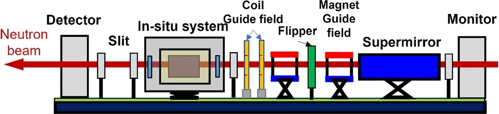
Fig. 6 (Color online) Schematic diagram of the experiment setup with all the devices along the neutron path. An adiabatic change in neutron polarization, after it has passed through a flipper,is achieved using a set of coils and a permanent magnet with mutually perpendicular magnetic fields

Fig. 7 Simulated variation of the neutron polarization after passing through the guide field
To extract information on the flipping efficiency, four separate measurements were taken by keeping the polarization direction of the supermirror constant. In measurements 1 and 2, the flipper remained turned off when the analyzer direction was(1)parallel or(2)antiparallel to the magnetic guide field.Measurements 3 and 4 were identical to measurements 1 and 2, but with the flipper turned on.The normalized intensity of the measurements is given by

5.3 Measurement result
A photograph of the experimental setup is shown in Fig. 8 and the measurement results are shown in Fig. 9.For polarized neutrons in the full wavelength range of 1.1-5.5 A°, the flipping efficiency exceeds 90%, and 99%for neutrons with wavelengths greater than 4 A°.

Fig. 8 (Color online) Photograph of the experiment setup, corresponding to the schematic diagram in Fig. 6. A neutron beam with a diameter of 10 mm was produced using neutron slits. The distance from the detector to the neutron source was 14.99 m

Fig. 9 (Color online) Experiment and simulation results for the flipping efficiency as a function of wavelength. The flipping efficiency data were obtained experimentally (black squares) and by simulating the final polarization of a fully polarized neutron beam after it has passed through the cryo-flipper and a guide magnetic field.The discrepancy in the wavelength regime of 1.1-2.5 A° may result from different adiabatic coefficients to which the neutrons are exposed, depending on whether they pass the guiding magnetic field either precisely at the center or some distance away from it
For a final comparison of the experimental results with the theoretical expectation, the calculated neutron precessions for the guide field and magnetic field inside the flipper were combined and overlaid onto Fig. 9.
The simulation results are consistent with the experiments for wavelengths above 2.5 A°. However, there is some deviation for shorter-wavelength neutrons, whose flipping efficiency is affected mainly by adiabatic processes in the magnetic guide field.For a neutron beam with a diameter of 10 mm, we speculate that considering only the magnetic field at the center of the neutron beam does not fully reflect its influence on the polarization of the entire neutron beam.
6 Neutron transmittance
The neutron transmittance of the cryo-flipper,taken as a function of wavelength, was measured using the experimental setup, as shown schematically in Fig. 10.

Fig. 10 (Color online) Schematic diagram of the transmittance measurement.The neutron beam,whose size is limited by the neutron slits, passes only through the flipper between the beam monitor and the detector
The results show the overall transmittance of neutrons in the wavelength range of 1.1-5.5 A° of more than 95%,with localized sharp minima near the aluminum, sapphire, and YBCO edges [26, 27] (Fig. 11).
7 Conclusion
We successfully designed, built, and commissioned a miniaturized TOF neutron spin flipper.The use of high-TC YBCO, its cooling by a Stirling refrigerator, and its optimized design achieved a further reduction in the overall size and reduced the installation and operational costs of the equipment. Measurements at the CSNS test beam line BL-20 showed that the polarization flipping efficiency exceeded 90% for the full wavelength band of 1.1-5.5 A°,greater than 99% for wavelengths greater than 4 A°, while maintaining a neutron transmittance of more than 95%.
The consistency of the simulations with experiments for longer wavelengths demonstrates their effectiveness at predicting the performance of the equipment and their suitability for conducting optimization before practical implementation.
The source of the deviation of the experimental results from the theoretical expectations in the shorter-wavelength

Fig.11 Measured neutron transmittance of the flipper.Minima in the spectrum correspond to the Bragg edges of aluminum, sapphire, and YBCO parts that intersect the neutron beam
regime cannot yet be fully determined. A likely explanation is that the polarization change of a sizeable polarized neutron beam passing through the magnetic guide field cannot be represented by only assuming polarized neutron beam behavior at the center of the path. Future work will seek to verify this conjecture and improve the flipping efficiency by optimizing the magnetic guide field settings.The angular deviation of the magnetic field around the superconductor discovered by FEM simulation is an important factor affecting the flipping efficiency in the short-wavelength range. Based on these findings, we will continue to optimize the design of electromagnets to meet the needs of polarized neutron experiments at higher energies.
AcknowledgementsWe give special thanks to Dr. Song-Lin Wang for the deployment of our instrumentation on BL-20.
Author Contributions All authors contributed to the study conception and design. Material preparation, data collection and analysis were performed by Yu-Chen Dong, Bo Bai, Jun-Pei Zhang, Long Tian and Chu-Yi Huang. Conceptualization, methodology and experiment design were performed by Tian-Hao Wang, Wolfgang Kreuzpaintner and Xin Tong. Software was designed by Xiao-Tao Liu, Ze-Hui Li and Yu-Dong Kang. The first draft of the manuscript was written by Yu-Chen Dong and all authors commented on previous versions of the manuscript.All authors read and approved the final manuscript.
杂志排行

Nuclear Science and Techniques的其它文章
- Design and fabrication of button-style beam position monitors for the HEPS synchrotron light facility
- Spectral baseline estimation using penalized least squares with weights derived from the Bayesian method
- Investigating core axial power distribution with multiconcentration gadolinium in PWR
- Optimization study and design of scintillating fiber detector for DT neutron measurements on EAST with Geant4
- Method for detector description transformation to Unity and application in BESIII
- Improvement of the Bayesian neural network to study the photoneutron yield cross sections