A Numerical Study on the Effect of Ignition Pattern on Wavelet Features in Rotating Detonation Waves
2022-12-08PENGAoZHANGJingwenCHENXianfengSUNXuxu
PENG Ao, ZHANG Jingwen, CHEN Xianfeng, SUN Xuxu
(School of Safety Science and Emergency Management, Wuhan University of Technology, Wuhan 430081, Hubei, China)
Abstract: In this study, the effect of ignition pattern on the wavelet features of rotating detonation waves (RDWs) is numerically investigated with Euler equations and two-step induction-reaction model. The influences of the size, the number and the spacing of the ignition zone were considered. The theoretical Chapman-Jouguet (C-J) detonation wave was used as the ignition zone, and different ignition patterns were obtained by changing the size of the C-J detonation wave. The numerical results indicate that the wavelet features of rotating detonation waves closely depend on the ignition zone size. Only the two-wave and the three-wave modes are observed for the single ignition zone with various sizes, and the relation between the quantity of RDWs and the ignition size is non-linear. For the single ignition zone with the same width, the occurrence probability of the two-wave mode is approximately greater than 80%, while the three-wave mode is a completely random phenomenon. The formation mechanisms of the multiple-wave modes can be summarized as follows: (1) the first RDW is directly produced from the initial C-J detonation wave near the top of the combustor; (2) the subsequent RDW is induced by the interaction between the compressed wave produced by the initial C-J detonation and the jet flow from the micro-nozzles. The quantity of RDWs increases with the quantity or the spacing of ignition zone, but their relations are both non-linear.
Keywords: ignition patterns;rotating detonation waves;wavelet features;compressed wave;jet flow
Combustion can be divided into two typical modes: deflagration and detonation. In propulsion systems,combustion is regarded as an important process, because it can convert chemical energy of fuels into heat by chemical reaction, and then into kinetic energy of the working medium to produce thrust. Deflagration concerns a combustion wave traveling at subsonic speed, and the wave velocity is of the order of meters per second. The overpressure across deflagration is approximately constant. Therefore, deflagration is usually considered as a nearly isobaric combustion. In contrast to deflagration, detonation concerns a combustion wave propagating at supersonic velocity with higher overpressure and temperature. The pressure (p) across detonation wave front is about 15-20 times the initial pressure,and the specific volume (V) decreases slightly. Thus,detonation is treated as a nearly isovolumic process.In Fig. 1, the Rayleigh lines and Hugoniot curve inp-Vdiagram[1]are shown. The initial state of combustible mixtures may turn out to be two different final states by deflagration and detonation. It is obvious that both the heat released and the thermal efficiency of detonation are higher than those of deflagration.

Fig. 1 Rayleigh lines and Hugoniot curve in p-V diagram[1]
Based on the discussion above, more and more attentions have been paid to detonation to provide thrust in propulsion systems. Particularly, the rotating detonation engine (RDE) is one of the most promising engines due to its high efficiency[2-3]. The so-called RDE refers to using one or multiple detonation waves to continuously provide steady thrust in an annular channel[4-6]. In the past decades, the characteristics of rotating detonation waves (RDWs) and the performance of rotating detonation engine have been given increasing attention because of its huge potential. The performance of RDE depends on many factors, e.g., the geometrical structure of combustor, the type of fuel, and the mixture injection,etc. Schwer,et al.[7]systematically explored the flow characteristics of RDW by changing the outer radius of the annular combustor, and the results indicate that RDW becomes more unstable with the increases of the outer radius. Afterwards, Zhou,et al.[8]numerically investigated the flow field of RDW along the radial direction, and found that there is a critical width of the annular combustor. Over time, the characteristics of flow field are approximately constant when the width of the annular combustor is smaller than the critical value. In addition, the effect of expansion wave on RDW was experimentally and numerically investigated by Katta,et al.[9], and different propagation modes were observed in hydrogen-air RDW. The phenomenon of multiple wave propagation modes was also observed in the study of Anand,et al.[10], but the underlying mechanisms of such fact is still not clear. Recently, Ma,et al.[11-12]systematically investigated the initiation characteristics of RDW using various ignition devices, and found that the initiation feature of RDW almost does not depend on ignition device. More recently, Teng,et al.[13]numerically analyzed the wavelet features in rotating detonations using two-step induction-reaction model. The theoretical Chapman-Jouguet (C-J) detonation wave was employed as the ignition zone, and three different ignition patterns were obtained by changing the size of the C-J detonation wave. The results indicated that the wavelet features closely depend on the ignition patterns, and the relation between the number of RDWs and the ignition size is non-linear.
In the studies of rotating detonation waves, due to the fact that the radial size of the combustor is far smaller than the axial dimension, the annular combustor can be unwrapped into two dimensions, and simplified twodimensional (2D) model are often employed. Hishida,et al.[6]and Tsuboi,et al.[14-15]comprehensively investigated the role of inlet pressure, Mach number, micro-nozzle area ratio and ignition energy on the performance of RDE using a 2D numerical model, and the Kelvin-Helmholtz instability existing on the interface of the injected combustible was analyzed for the first time. Shao,et al.[16-18]and Zhou,et al.[8,19]also systematically investigated the performance of RDE in many aspects, e.g. detailed flow structure, nozzle effects, fuel injection limit, viscous effects. Schwer,et al.[20-21]numerically analyzed the effects of injection pressure, engine size and inlet model on the flow field of RDW in hydrogen-air mixtures. Uemura,et al.[22]and Liu,et al.[23]systematically explored the instabilities in another 2D RDW model by analyzing the characteristic of the transverse waves and the oscillations of detonation height/pressure.
This study aims to investigate the effect of ignition pattern on the wavelet features in a 2D RDW model based on the two-step induction-reaction model. In the two-step induction-reaction model, the first step is for induction zone, where the reactants are activated to produce free radicals, and the second step is for reaction zone,where the reactants are transferred to products. The influences of size, number and spacing of the ignition zone are studied systematically. The theoretical C-J detonation wave is used as the ignition zone, and various ignition patterns are obtained by changing the size of the C-J detonation wave. Although the effects of ignition pattern size on propagation characteristics in rotating detonations have been considered in the study of Teng,et al.[13], the underlying mechanisms of multiple wave propagation modes is still not clear, and the number and the spacing of the ignition zone are not investigated. Therefore, the effect of the ignition zone on the RDW is still worth studying.
1 Numerical Model and Methods
Fig. 2 shows the schematic diagram of the initiation of rotating detonation waves. Herein, the ignition zone is a self-sustained C-J detonation wave, which is firstly calculated in a tube and then cut and pasted for further analysis. Various ignition patterns can be obtained by changing the size of the C-J detonation wave (with a length ofL1and a width ofL2), as shown in Fig. 2(a). In addition, the quantitynand the spacingdof the ignition zone in combustor are also variable, as shown in Fig. 2(b) and Fig. 2(c), and their effects on RDWs are considered. For the cases of several ignition zones, four spacings are employed, i.e.,d=40, 60, 80 and 120, and three quantities of the ignition zone are employed, i.e.,n=1, 2 and 3, however, each ignition zone is fixed atL1=150 andL2=40. Herein,the size of the calculation domain is 360 × 240, and the grid quantity is 7 200 × 4 800.
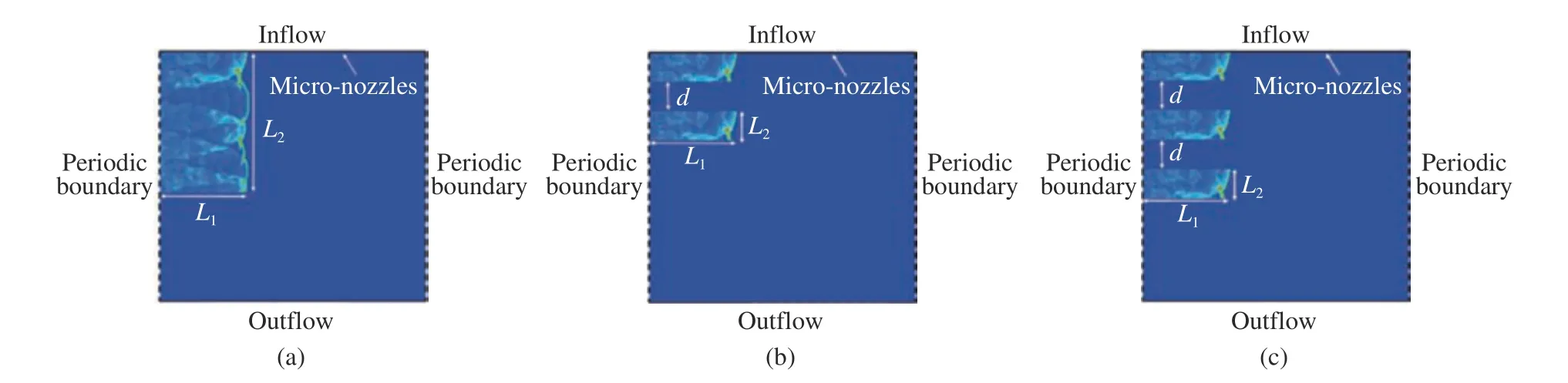
Fig. 2 Schematic diagram of the initiation zone in combustor
The reactive Euler equations neglecting of viscous and diffusive effects are used as the governing equations to simulate rotating detonation waves, which are given as below

where theUis the conserved variable,FandGare the convective fluxes andSis reactive source term,Tis temperature, ρ is the density,uandvare the velocities at two directions, ξ and λ are the progress variable in the induction stage and the reaction stage,w˙Iis the reaction speed in the induction zone,w˙Ris the reaction speed in the reaction zone, theneis the total energy per unit mass.
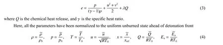
whereRis the product of the gas insulation index and the molar constant of the ideal gas, the subscript zero represents the initial state, and the superscript wavy line represents the state at a certain moment. In addition, the two-step induction-reaction rate law is considered in this study with an additional advection equation for the progress variable in the induction stage ξ. The reaction rate in the induction zone and the reaction zone can be written as follows

whereTSis the post-shock temperature,EIis the activation energy in induction zone,ERis the activation energy in reaction zone,KIis the pre-exponential factor in induction zone, andKRis pre-exponential factor in reaction zone.HereH(1-ξ) represents the step function

In the two-step induction-reaction law, the parameterxrefis employed as the reference length, and the one-dimensional Zel’dovich-von Nenmann-Döring (ZND) induction zone lengthΔIis unity, i.e.,kI=-uvn(uvnrepresents the Van-Neumann speed). The above equations are solved using a 2ndorder MUSCL-Hancock scheme with an HLLC Riemann solver[24]with a Courant-Friedrichs-Lewy (CFL) number of 0.90.
The stoichiometric hydrogen-air mixture is employed as the test gas. The premixed hydrogen-air mixture is injected into a combustor by many micro-nozzles at the top side. The ratio of the injection area of the combustor to the throat area of the micro-nozzles is fixed at 4.0. The mixture parameters and corresponding ZND C-J detonation properties are presented in Table 1.

Table 1 Stoichiometric hydrogen-air mixture parameters and corresponding ZND C-J detonation properties
2 Results and Discussion
2.1 RDW Structure and Resolution
The density flow fields of RDWs calculated are presented in Fig. 3 in the case of single ignition zone. The common wave structures are observed, including an oblique detonation, an oblique shock wave and a contact front between fresh combustible mixture and burned products. The wave structures obtained in present study are consistent with previous references[13,25]. Two grid scales, with the resolution of 10 and 20, are used to verify that the simulated results are not affected by the calculated resolution. Herein, the resolution represents the quantity of grids per ZND induction zone length. From Fig. 3, it can be found that both the two resolutions are sufficient to calculate the wave structures. However, this study focus on the effects of ignition pattern on the wavelet features of RDWs, thus the larger resolution of 20 is used to get more accurate data subsequently in this study.

Fig. 3 Density field from RDW numerical results for the ignition size of L1=210 and L2=280 and resolutions of 10 (a) and 20 (b)

Fig. 4 Density fields of RDWs for one ignition zone with different sizes
2.2 Effect of Ignition Pattern
The effect of the size of ignition zone on wavelet features of RDWs is calculated and presented in Fig. 4. In this study, only two-wave (e.g.,L1=150,L2=40) and three-wave modes (e.g.,L1=150,L2=210) are observed and the wavelet features closely depend on the ignition size. The wave height decreases with the increase of the quantity of RDWs. Compared the results with that of Teng,et al.[13], the disappearance of single-wave mode can be due to the different ratio of the injection area of the combustor to the throat area of the micro-nozzles used herein. This phenomenon indicates that the quantity of RDWs is related to many factors. The formation mechanism of twowave and three-wave modes can be attributed to the interaction between the jet flow from the micro-nozzles and the shock wave from the ignition patterns, and the detailed explanation has been provided by Zhao,et al.[26]recently.
The temperature fields and the schlieren as a function of time for the ignition zone with the size ofL1=150 andL2=40 are shown in Fig. 5 and Fig. 6, respectively. It can be found that the initial C-J detonation wave is decoupled rapidly at the bottom of the ignition zone. This is caused by the effect of the rarefaction waves.However, the C-J detonation wave near the micro-nozzles maintains a self-sustained propagation at the top of the combustor, and then it progressively forms the first rotating detonation wave (see Fig. 5(f) and Fig. 6(f)).Afterwards, the second rotating detonation wave is induced (see Fig. 5(i) and Fig. 6(i)). The second RDW is induced by the interaction between the compressed wave produced by the initial C-J detonation and the jet flow from the micro-nozzles. Thus, the formation mechanisms of the multiple-wave modes can be summarized as follows: (1) the first RDW is directly produced by the initial C-J detonation wave near the top of the combustor;(2) the subsequent RDW is induced by the interaction between the compressed wave produced by the initial C-J detonation and the jet flow from the micro-nozzles.

Fig. 5 Temperature fields of RDWs at different instants for L1=150 and L2=40

Fig. 6 Schlieren records of RDWs at different instants for L1=150 and L2=40
In the study of Teng,et al.[13], the ignition zone is divided into weak ignition, medium ignition and strong ignition based on its size, and the maximum quantity of RDWs is obtained for the medium ignition. This indicates that the relation between the quantity of RDWs and the ignition size is non-linear. This phenomenon is attributed to more rarefaction waves at the end of the initial C-J detonation wave for the case of strong ignition[13], which reduce the released energy and suppress the formation of RDWs. However, in this study, it is found that the threewave mode is prone to appear as the size of the ignition zone increases. Fig. 7 shows the quantity of RDW for the ignition zone with different sizes. ForL1=190, besides smallL2in the range of 40-80, the three-wave mode is seen whenL2is in the range of 270-300, that enriches the related conclusion given by Teng,et al.[13]. In fact,it can be seen that the occurrence of the three-wave mode may be a random phenomenon based on our numerical results. Fig. 8 gives the pressure records of RDWs. The distance in Fig. 8 represents the propagation distance of RDWs. The pressure peak value fluctuation is more significant for large RDW quantity,that is caused by the strong instability induced by the ignition patterns. In this study, two-wave mode or three-wave mode can be seen for the ignition zone with the same widthL1(as shown in Fig. 7). Fig. 9 gives the probabilities of the occurrence of two-wave and three-wave modes for the sameL1. It shows that the probabilities of the occurrence of two-wave mode is nearly greater than 80% for the sameL1.
The effects of quantity and spacing of ignition zone on the wavelet features of RDWs are considered as well.To compare with the previous results, the size of the single ignition zone is fixed toL1=150 andL2=40. The wavelet features of RDWs are investigated under different quantities and spacings of the ignition zone. Singleignition source, double-ignition source and three-ignition source are employed, and three different spacings between ignition sources, i.e.,d=40, 60 and 80, are used. The numerical results are presented in Fig. 9 and Fig. 10.The results indicate that the quantity of RDWs increases with the number and the spacing of ignition sources, but the relation between them are both non-linear. For two ignition sources, the quantity of RDW is increased from 2 to 3, and it is closely related to the spacing of ignition sources. Three-wave mode is observed at the conditions ofd=40 and 60 for two ignition sources. However, the quantity of RDWs decreases from 3 to 2 when the spacing of ignition sources increases to 80 (see Fig. 10). For three ignition sources, the quantity of RDWs is always 2 for various spacings (see Fig. 11). Moreover, a counter-clockwise flow in combustor is observed. The reason for the couterclockwise flow appearance is as below: firstly, due to the diffraction effect, the first RDW induced by the initial C-J detonation is failed eventually (as shown in Fig. 12(a)); secondly, a counter-clockwise RDW is formed by the interaction between the compressed wave and the jet flow (see Fig. 12(b), Fig. 12(c) and Fig. 12(d)).

Fig. 7 Quantity of RDWs for the ignition zone with different sizes

Fig. 8 Pressure records of RDWs for various ignition patterns
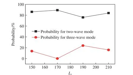
Fig. 9 Probabilities for two-wave and three-wave modes

Fig. 10 Density fields of RDWs for the case of two ignition sources
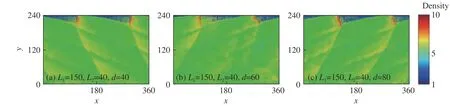
Fig. 11 Density fields of RDWs for the case of three ignition sources

Fig. 12 Density fields of RDWs for d=40 in the case of three ignition sources
3 Conclusions
In this study, the effects of size, quantity and spacing of ignition zone on the wavelet features of RDWs are numerically investigated with Euler equations and two-step induction-reaction model. Some interesting conclusions are obtained.
(1) The numerical results indicate that the wavelet features of RDWs closely depend on the ignition patterns.Moreover, only the two-wave and three-wave modes are observed for various ignition patterns, and the relation between the quantity of RDWs and the ignition size is non-linear. The probability of the occurrence of the twowave mode is approximately greater than 80% for different ignition patterns with the same width, and the occurrence of the three-wave mode is completely random.
(2) The formation mechanisms of the multiple-wave modes can be summarized as follows: the first RDW is directly produced by the initial C-J detonation wave near the top of the combustor, and the subsequent RDW is induced by the interaction between the compressed wave produced by the initial C-J detonation and the jet flow from the micro-nozzles.
(3) The quantity of RDWs increases with the quantity and the spacing of ignition zone, but the relation between them are both non-linear.
Acknowledgements:Many thanks to Prof. Ng and Dr. Mi for their guidance and help in numerical calculations.
