BIM-based construction technologies for precast foamed lightweight concrete wallboards
2022-10-18LinJiankangChenZhongfanDingXiaomengFengYanZhangJiaheng
Lin Jiankang Chen Zhongfan Ding Xiaomeng Feng Yan Zhang Jiaheng
(Key Laboratory of Concrete and Pre-stressed Concrete Structures of Ministry of Education, Southeast University, Nanjing 210096, China)
Abstract:To promote the visualisation and informatisation of the construction process of precast foamed lightweight concrete wallboards (PFLCWs), from the analysis of the construction requirements of PFLCWs, three key construction technologies based on building information modelling(BIM), namely, parameterised modelling for the PFLCW layout design, drawing generation to draw the PFLCW layout and quantity statistics for extracting PFLCW quantities, are proposed. Then, a reinforced concrete (RC) frame infilled with PFLCW is considered the test model to verify the feasibility of the aforementioned technologies. The results show that PFLCW layout design can be accomplished rapidly and visually using parameterised modelling technology. The PFLCW layout diagram can be generated directly using drawing generation technology. The proposed quantity statistics technology enables the automatic export of PFLCW bills of quantities. The built parameterised model helps construction workers rapidly and intuitively understand the specific layout details of PFLCWs. Moreover, the generated layout drawing and the bills of quantities based on the parameterised model can guide the production and on-site installation of PFLCWs. The research conclusions can serve as a practical guide and technical support for PFLCW engineering applications.
Key words:building information modelling(BIM); precast foamed lightweight concrete wallboard(PFLCW); construction visualisation and informatisation; parameterised modelling; quantity statistics
Precast lightweight wallboards have widely replaced brick blocks as building components for prefabricated buildings because of their advantages, such as dimensional standardisation, production industrialisation and installation assembly[1]. Our team proposes a kind of standardised precast foamed lightweight concrete wallboard (PFLCW) made of foamed lightweight concrete[2]and has developed a preparation process[3], casting mould[4]and installation equipment to realise the standardised design, factory production and mechanised installation of PFLCW. PFLCW can meet the dimensional requirements of most residential infill wallboards and has great potential for application because of its superiority in thermal insulation, sound insulation and fire protection[5].
Recently, building information modelling (BIM) technology has been widely used in the field of building engineering because of its advantages in visualisation, informatisation, simulation and optimisation[6]. At present, the following aspects of the research have been focused on by scholars: model deepening design[7], site layout[8], virtual construction[9-10], model lightweight processing based on BIM + Web GL[11-12], component tracking based on BIM + Internet of Things[13]and component quality inspection based on BIM + three-dimensional (3D) scanning[14]. Moreover, some researchers investigated the use of BIM technology in enclosure walls; however, they mostly focused on masonry engineering[15]. Meanwhile, the research on and application of BIM in PFLCWs have not been documented thus far. Furthermore, because CAD is typically used for layout design and quantity statistics during the construction of PFLCWs, this low visualisation and informatisation method is unable to intuitively display the spatial position of PFLCWs, which makes it difficult to ensure the accuracy and efficiency of the quantity statistics, somewhat restricting the development of PFLCW construction toward informatisation. Therefore, systematic research on how to use BIM technology to improve the efficiency of PFLCW construction and promote the informatisation and digitisation of PFLCW construction needs to be conducted.
In this study, taking PFLCWs as the research object, the construction requirements of PFLCWs are first analysed. Then, using BIM, a parameterised modelling method for PFLCWs is developed. Finally, the layout drawing generation method and the quantity generation framework for PFLCWs based on the parameterised model are investigated. Notably, the method proposed in the study is equally relevant to lightweight wallboards made from other materials.
1 BIM Application Strategy
The three key construction technologies based on BIM, namely, parameterised modelling technology for PFLCW layout design, drawing generation technology for PFLCW two-dimensional (2D) layout drawings, and quantity statistics technology for PFLCW quantity extraction, are purposefully presented by analysing the construction requirements of PFLCWs (see Fig.1). Furthermore, the corresponding implementation methods are developed for the aforementioned technologies. First, a BIM-based parameterised modelling method for the 3D layout design of PFLCWs is proposed. Then, based on the built parameterised model, a flow for generating PFLCW layout drawings and a framework for automatically exporting the bills of quantities using the Revit secondary development are established.

Fig.1 Building information modelling application flowchart
2 BIM-Based Parameterised Modelling Method for PFLCW
2.1 Methodology
Because PFLCW is characterised as having a few types and many quantities, its modelling process has the problems of heavy modelling workload and poor information transmission efficiency. These problems can be effectively resolved using a BIM-based parameterised modelling method for PFLCWs, which can be divided into two steps. The first step is to establish a PFLCW parameterised family by parameterising the dimension and attribute information of the standard PFLCW component. The second step is comprised of the following processes: 1) selecting the type of PFLCW according to the functional requirements of the room; 2) realising the rapid positioning and assembly of the PFLCW by controlling the plane position and vertical coordinates of the PFLCW based on the modelling principle of point (component) → line (enclosure wall) → surface (room); 3) establishing the overall assembly model filled with PFLCW. In this study, Revit is used to complete the parameterised modelling of the PFLCW.
2.2 Parameterised family of PFLCW
The flowchart for building the PFLCW parameterised family mainly includes the following steps: 1) classifying the PFLCW; 2) clarifying the control parameters (i.e. dimension and attribute parameters); 3) creating the parameterised family; and 4) debugging the parameterised family model. Among them, the dimension parameters are mostly used to change the shape of the PFLCW, whereas the attribute parameters are primarily used to store the material information, item name and item code. Given the large number of PFLCWs in the model, modelling PFLCWs with different sizes can be easily achieved by modifying the instance parameter. Then, the family parameter is chosen to be the instance parameter.
To obtain the quantitative classification statistics, PFLCW is initially split into precast FLC exterior wallboard with a width of 200 mm and precast FLC interior wallboard with a width of 120 mm. Then, their parameterised families are established. The specific modelling steps include the following: 1) loading the metric conventional model family file; 2) using the stretching command to create the geometric model and add the model dimension parameters, such as length, width and height; 3) considering the influence of the door and window openings in setting a transparent shear body with the same wallboard width to control the opening location and the dimension using parametersa,b,candd; 4) adding the attribute parameters. Tab.1 lists the set PFLCW family parameters.

Tab.1 Family instance parameters of precast FLC wallboards
2.3 A case of modelling an RC frame structure
A typical three-layer, three-span RC frame structure is taken as an example for the parameterised modelling of PFLCWs. Fig.2 exhibits the structural model with a plan layout of 21.6 m × 14.7 m, a column section of 500 mm × 500 mm, a beam section of 300 mm × 600 mm, a first-floor height of 3 600 mm and second- and third-floor heights of 3 000 mm.

(a)

(d)
The overall assembly model filled with PFLCW is built using the parameterised modelling method, as shown in Fig.3. The parameterised family can satisfy the rapid generation of components of various sizes and shapes, improving the layout efficiency of PFLCWs in the structure model. Meanwhile, the established parameterised model can provide model support for the following research on model-based drawing generation and model-based quantity generation of PFLCWs.

Fig.3 Overall assembly model
3 Model-Based Drawing Generation Flow for PFLCW
A generation flow for PFLCW layout drawing is proposed based on the parameterised model, as shown in Fig.4, which mainly consists of the following steps: 1) creating the drawing family; 2) creating the model views: the PFLCW-assembled enclosure wall models are first classified and the corresponding views are then created by cutting the models; 3) placing the model views in the created drawing; 4) adding dimensions and text annotations to the drawing; 5) exporting the drawing.
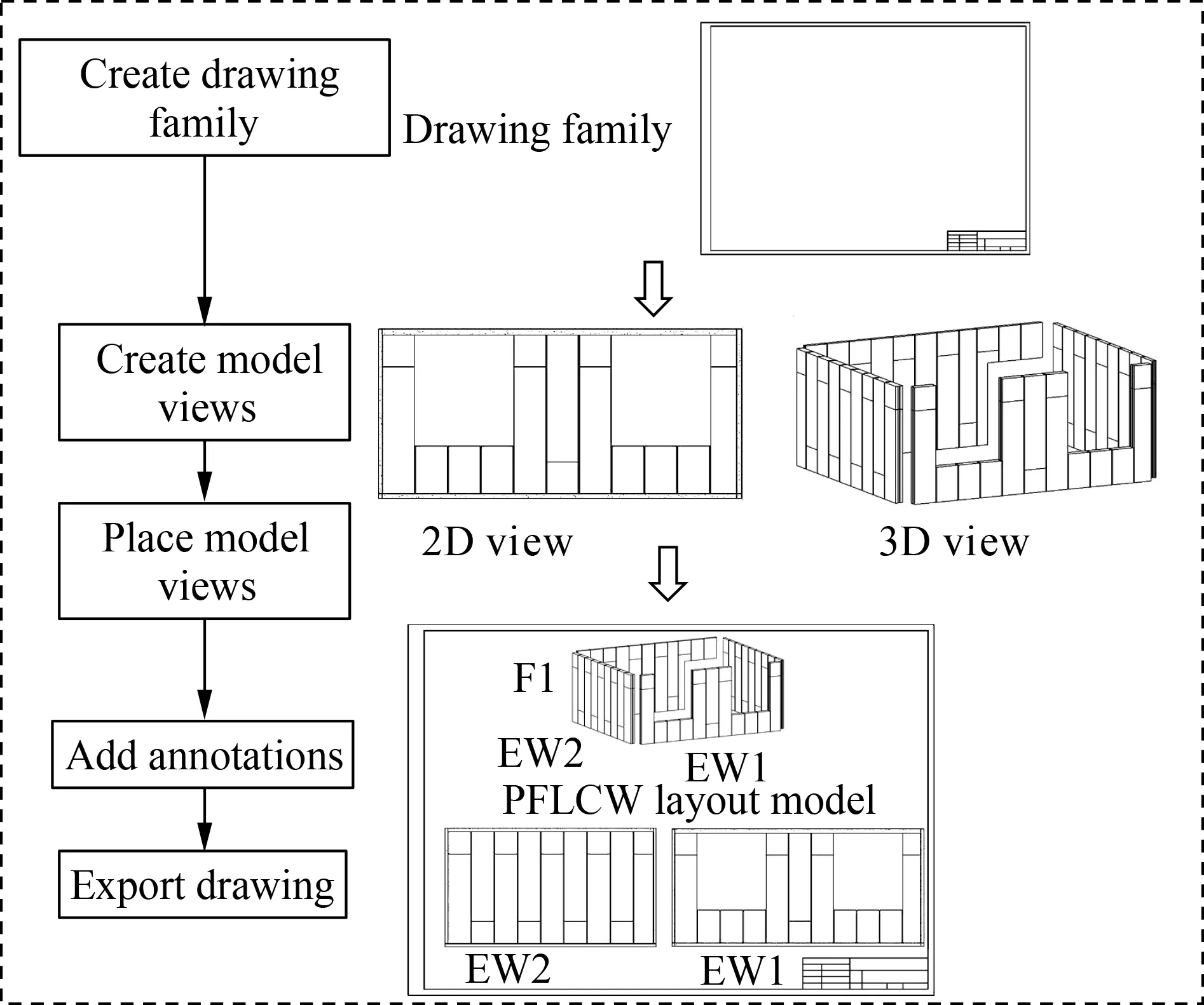
Fig.4 Implementation flow
The PFLCW layout drawing created using the proposed method is displayed in Fig.5. The enclosure wall is divided into EW11, EW12, EW13, EW14 and EW15 in the picture. The model-based drawings created are correlated with the model in real time, and the PFLCW cutting information simulated in the model is associated with the PFLCW layout drawing in real time. The proposed method is different from the traditional 2D drawing method. The proposed method realises 3D + 2D visual drawing generation, which enhances the visual expression of the drawing and helps guide construction, making up for the poor operation accuracy and low operation efficiency caused by the lack of experience of construction workers in the traditional construction mode to a certain extent.

Fig.5 PFLCW layout drawing (unit: mm)
4 Model-Based Quantity Generation Framework for PFLCW
4.1 Methodology
The extraction of information from the BIM model can provide data support for the construction process of a building[16]. A framework is established for model-based automatic quantity generation, as displayed in Fig.6, which is divided into three parts, namely, the regularisation of component coding, the standardisation of the quantity table and the automation of information extraction. By running the developed programme, the framework can extract the PFLCW information from the BIM model and immediately output Excel files.

Fig.6 Framework of the method
4.2 Component coding
Component coding is the basis for quantity statistics, which is divided into three parts, namely, item code, item name and component characteristic.
Item code is used to classify the bills of quantities by the unique item code. The four-level hierarchical coding is taken to name the item code in digital form following the Chinese code GB/T 51269—2017[17], and the different levels are connected by “.”, as shown in Fig.7. The first-level coding represents the speciality category, where 10 indicates the architecture speciality. The second-level coding represents the subdivisional work, where 03 indicates the concrete project. The third-level coding represents the component type, where 40 indicates the precast wallboard. The fourth-level coding represents the component name, where 30 indicates the PFLCW.

Fig.7 Item code
The item name is used to determine the object of quantity, corresponding to the item code, which is PFLCW in this study.
The component name is used to distinguish between PFLCW components in the parameterised model. The three-level hierarchical description is used to name the components in this paper with “-” connecting different levels. The first-level description indicates the component number, where OW represents the exterior wallboard, IW represents the interior wallboard, 10 represents the wallboard without an opening, and 20 represents the wallboard with an opening. The second-level description indicates the size of the component, that is, describing the length, width, and height of components without an opening and the length, width, and opening height for components with an opening. The third-level description indicates the component material information.
4.3 Determination of extracted parameters
Three methods to obtain the model parameters are provided in the Revit API, namely, BuiltInParameter, LookupParameter and Property. The mapping relationships between parameters in the bills of quantities and parameters in Revit are shown in Tab.2, where BuiltInParameter and Property are used to extract the system parameters stored in the model, whereas LookupParameter is used to extract the custom parameters stored in the model.

Tab.2 Mapping relationships between parameters
4.4 Programme development for automatic data extraction
4.4.1 Development tools
In this study, the quantity extraction programme is developed using the extended command provided by the Revit API. Visual Studio 2019 is selected as the programming tool, and C# is used as the programming language during secondary development[18].
4.4.2 Development process
The programme development process is depicted in Fig.8. The primary implementation steps and programme code are as follows:
1) Obtain the current document of the model using commandData. Application.ActiveUIDocument.Document.
2) Obtain all family instances
The programme will obtain all family instances in the selected document through the filtering component category, and the filtered family instances are stored in the created collector.
var collector = new FilteredElementCollector(doc)
var categoryFilter =collector.OfCategory(BuiltIn-Category.OST_GenericModel)
var classFilter = categoryFilter.OfClass(typeof(FamilyInstance))
3) Extract the parameters
First, the PFLCW family in the collector is selected through item encoding. Then, the foreach command is utilised to traverse the collector. Finally, the BuiltInParameter, LookupParameter and Property interfaces are called to obtain the parameters used for generating the PFLCW quantity table.
foreach (FamilyInstance parameter in the collector)
{var XMBM = parameter. LookupParameter (item code);

Fig.8 Flow of programme development
var zuName = parameter.get_Parameter
(BuiltInParameter. ELEM_FAMILY_PARAM);
var ID = parameter. Id;
……}
4) Export Excel table
The extracted data are inputted into the created Excel table by citing the Excel class library NPOI in Visual Studio and saving the Excel file to the specified path.
4.5 Result analysis
With the parameters listed in Tab.2 selected as the statistical parameters, the model shown in Fig.3 is used to test the effectiveness of the framework.
4.5.1 Validation
The bills of quantities for some PFLCW formed by the model-based quantity generation framework are shown in Tab.3. The development programme can automatically export the bills of quantities and directly extract the item code, item name, family name, component ID, component name, level, length, width, height, volume and weight of the PFLCW, demonstrating the effectiveness and feasibility of the model-based method. The extraction and modelling of the quantity statistics of PFLCW are conducted using Revit without the help of professional quantity statistics software to ensure no loss and error in information transmission. This approach not only ensures the accuracy of the extracted data but also improves the efficiency of engineering quantity statistics and the utilisation rate of information in the parameterised model.

Tab.3 Results of quantity statistics
4.5.2 Quantity of the components
Before the production of precast components, the amount and material dosage of the components required for construction need to be determined.
The statistical results shown in Tab.4 indicate that the volume and number of components can be obtained by the framework. The volume and amount of PFLCW obtained using the model can provide an accurate basis for the material procurement required for PFLCW production, facilitating the rational arrangement of raw materials and mould and helping with the improvement of production efficiency and the reduction of the construction period.

Tab.4 Quantity results
4.5.3 Information on the components
The on-site installation of PFLCWs can be directed by obtaining accurate and effective dimensional information. Using the dimensional information of the PFLCW shown in Tab.5, combined with the layout drawing of the PFLCW (see Fig.5), construction workers can intuitively understand the shape features of each component, accurately guide cutting the PFLCW on-site, reduce material waste and improve the efficiency of PFLCW installation. Moreover, the on-site transportation of PFLCW can be conveniently arranged using the extracted component weight.
In summary, the advantages of BIM in PFLCW construction are mainly reflected in the following aspects: Parameterisation, visualisation and informatisation. For parametrisation, the parameterised modelling method based on BIM can realise the rapid modelling of different sizes of PFLCWs through the use of a standardised parameter family. For visualisation, the 3D BIM model with the advantage of visualisation helps construction workers understand the precise layout details of PFLCWs intuitively. For informatisation, the model built using the parameterised modelling method provides dimension and attribute information that can be used for the quantity statistics of PFLCW. Therefore, the use of BIM technology helps guide the construction of PFLCWs in the manner of visualisation and informatisation, to a certain extent, making up for the poor accuracy and low efficiency of the PFLCW layout design and quantity statistics under the 2D CAD mode.

Tab.5 Component information of the PFLCW
5 Conclusions
1) The constructed BIM-based parameterised modelling method can improve the layout design efficiency of PFLCWs and store the parameter data in the model for quantity statistics.
2) The proposed drawing generation method can realise model-based forward drawing and improve the generation efficiency of PFLWC layout drawing.
3) The automatic generation of PFLCW quantities is realised by establishing the model-based quantity generation framework while ensuring the reliability and efficiency of quantity statistics.
4) This study primarily focused on the implementation of the PFLCW parameterised modelling method. Thus, further research on the quantitative analysis of PFLCW layout efficiency is needed. To further promote the digital construction of PFLCWs, application research for new technologies should be conducted. Examples include the automatic arrangement of PFLCW based on intelligent algorithms, construction simulation and construction management based on visualisation platforms.
杂志排行

Journal of Southeast University(English Edition)的其它文章
- Improved PBFT protocol based on phase voting and threshold signature
- Predictive current control system of PMSM based on LADRC
- Temperature prediction model for a high-speed motorized spindle based on back-propagation neural network optimized by adaptive particle swarm optimization
- Analysis on resonant shake table with novel variable stiffness mechanism
- Analysis on degradation behaviors of sisal fibers at various pH conditions
- Application of polypyrrole nanofibers in the selective extraction of methotrexate and its polyglutamate metabolites from hospital effluents