A modified time domain interpolation method for LS channel estimation in OFDM systems
2022-10-18ZhangYenanXuFeiyunJiaMinping
Zhang Yenan Xu Feiyun Jia Minping
(School of Mechanical Engineering, Southeast University, Nanjing 211189, China)
Abstract:A modified time domain interpolation method is proposed for orthogonal frequency division multiplexing (OFDM) systems to address the problem that time domain interpolation in the least square (LS) channel estimation method based on comb-type pilots cannot choose the pilot spacing flexibly. Firstly, the estimated channel frequency response (CFR) at pilot positions in the frequency domain is obtained by LS channel estimation based on comb-type pilots, and the estimated channel impulse response (CIR) in the time domain is obtained by linear interpolation and inverse fast Fourier transform (IFFT). Secondly, the error of the estimated CIR obtained by linear interpolation is analyzed by theoretical deduction, and a method for correcting it is proposed. Finally, an estimated CFR at all subcarrier positions in the frequency domain is obtained by performing zero padding in the time domain and fast Fourier transform (FFT) on the modified CIR. The simulation results suggest that the proposed method gives similar performance to time domain interpolation, yet it does not need to meet the condition of time domain interpolation that the number of subcarriers must be an integral multiple of pilot spacing to use it. The proposed method allows for flexible pilot spacing, reducing the number of pilots and the consumption of subcarriers used for channel estimation.
Key words:orthogonal frequency division multiplexing (OFDM); channel estimation; linear interpolation; time domain interpolation
Orthogonal frequency division multiplexing (OFDM) is a multicarrier modulation technique with high bandwidth efficiency, high transmission rate, and robustness to multipath fading. It has been adopted in wireline applications such as digital audio broadcasting (DAB)[1], underwater acoustic communication (UWA)[2], and digital video broadcasting (DVB)[3], fifth generation (5G)[4], etc.
Channel estimation is essential for OFDM systems; the influence of the channel needs to be estimated at the receiver. Pilot-based approaches are widely used in channel estimation. Pilot tones can be inserted into the time domain or frequency domain, called block-type and comb-type. The comb-type pilot arrangement has better performance than the block-type for fast-fading channels[5]. The estimated channel frequency response (CFR) at the pilot positions can be obtained by least square (LS) or minimum mean square error (MMSE)[6]. MMSE algorithm provides better performance with high complexity. LS algorithm utilizes the least-squares criterion and has been widely used due to its low complexity.
The LS estimated CFR is interpolated to obtain CFR at all subcarriers. The interpolation methods can be divided into frequency domain interpolation, transform domain interpolation, and time domain interpolation. The frequency domain interpolation methods include linear interpolation, Gaussian interpolation, and spline cubic interpolation[7]. Transform domain interpolation uses the discrete Fourier transform (DFT) to transform the LS estimated CFR into the transform domain. High-resolution interpolation with low complexity is based on zero-padding in the transform domain and inverse DFT (IDFT)[8].
Time domain interpolation has a similar process to transform domain interpolation. The LS estimated CFR is transformed into the time domain by IDFT, and the estimated channel impulse response (CIR) is obtained. CFR at all subcarriers is obtained by zero padding and DFT. Time domain interpolation has been proven to have a lower bit error rate (BER) than linear interpolation[7]. Time domain interpolation has a better performance than transform domain interpolation, as shown in Ref.[8]. Furthermore, as demonstrated in Ref.[9], time domain interpolation outperforms linear, cubic, and low pass interpolation. Time domain interpolation has been investigated for OFDM systems with virtual subcarriers in Refs.[10, 11].
Time domain interpolation is accurate if the channel delays are integral multiples of the sample time of the OFDM symbol and the sample length of CIR is less than the number of pilots[12]. Furthermore, DFT and IDFT are easy to realize using the fast Fourier transform (FFT) algorithm[13]. Thus, time domain interpolation is widely used. Noise has the potential to affect LS, and noise reduction in the time domain is widely used[14-16]. Time domain interpolation is realized by zero-padding in the time domain. Therefore, it can be used with various time domain noise reduction methods.
However, pilot subcarrier spacing is determined by the channel’s maximum excess delay[11]. The pilot subcarriers used in channel estimation will consume a significant amount of subcarrier resources for the channel with a large delay spread[17]. To use time domain interpolation, the number of subcarriers must be an integral multiple of the pilot subcarrier spacing[18], which may cause a larger consumption of pilots. A reasonable pilot spacing should ensure good channel estimation performance while minimizing the number of subcarriers consumed by the pilots[19]. The subcarriers’ distribution is essential, especially for applications with narrow channel bandwidth[20-21].
In this paper,the modified time domain interpolation method is proposed to address the disadvantage of time domain interpolation in which the number of subcarriers must be an integral multiple of the pilot subcarrier spacing. Firstly, the OFDM system model is presented and the relationship between the estimated CIR from LS based on linear interpolation and the actual CIR is analyzed. Secondly, the disadvantages of time domain interpolation are examined and a modified time domain interpolation method is proposed. Then, simulation results are presented and analyzed.
1 Analysis of LS Channel Estimation Based on Linear Interpolation
1.1 System model
We consider an OFDM system that hasNsubcarriers. The transmitted signal at each subcarrier is {X[k],k=0, 1, …,N-1}, wherekrepresents the subcarrier index. The transmitted signal is transformed to a discrete-time domain by IDFT, given by
(1)
wherenis the sample index of the OFDM signal in the time domain. This is the modulation process of the OFDM system. Considering the effect of multipath effects, discrete-time CIR is given by
(2)
wherelis the index of the different paths;αlis the path complex gain of thel-th path;τlis the delay of thel-th path; andLis the total number of channel paths. If reasonable CP guard samples are used after passing through a multipath channel and removing CP, the received OFDM signal is represented by
r[n]=x[n]⊗h[n]+z[n]
(3)
where ⊗ denotes anN-point circular convolution operation, andz[n] denotes time domain samples of independent and identical distributed additive white Gaussian noise (AWGN). Assuming perfect synchronization, thek-th subcarrier symbol in the frequency domain is given by
R[k]=DFTN{r[n]}=X[k]H[k]+Z[k]
(4)
whereZ[k] are AWGN samples in frequency domain.Z[k]=DFTN{z[n]},H[k]=DFTN{h[n]}, and DFTN{} representsN-point DFT.
By inserting pilot tones at some subcarriers,CFR at pilot positions can be obtained by
(5)
This method is called LS estimation.
1.2 Analysis of linear interpolation


(6)

(7)
(8)
whereWN=exp(-j2π/N), called the rotation factor. By the properties of the rotation factor[22], we have
(9)
when 0≤n≤K-1,

(10)
By Eqs.(9) and (10), we have
(11)
wherePN,m[n] is defined by
(12)
The condition thatN/mis not an integer is then considered, and the other conditions are the same. The number of pilotsK=

(13)

(14)
WhenNis large, the last two parts of Eq.(14) are insignificant. Then we have
(15)
2 Proposed Interpolation Method
2.1 Analysis of time domain interpolation

(16)

(17)
The second one is padding at the middle of the sequence[23], given by
(18)
The first one is studied in this paper.
The estimated CFR at all subcarriers is obtained byN-point FFT:
(19)

(20)
(21)
As a result, time domain interpolation is a high-resolution method that is easy to realize. However, the number of subcarriersNmust be the integral multiple of the pilot spacingmto use time domain interpolation, i.e.,N/mmust be an integer.mis determined by the maximum delayτm. The maximum pilot spacing that satisfiesτm≤Kdoes not always satisfy the requirement of time domain interpolation. Smaller pilot spacing can be designed to satisfy both requirements, but it increases the number of pilot subcarriers and reduces system efficiency. To overcome the limitation of time domain interpolation, the modified time domain interpolation method is proposed.
2.2 Modified time domain interpolation

(22)
AssumingmK/N≈1 andWN≈WmK, similarly to Eqs.(20) and (21), we have
(23)

(24)
PmK,m[n] is close to 0 whennis close toK, as shown in Fig. 1.
In Eq.(15),I[n] in Eq.(14) is ignored. The error of Eq.(15) is given by
(25)
The smaller the value ofPmK,m[n], the greater the error caused by simplification in Eq.(15), and the error becomes significant whennis close toK. Thus, considering the accuracy of calculation and ease of implementation, the last quarter ofPmK,m[n] with a smaller value is discarded, and the approximate calculation results of
h[n] are as follows:
(26)
(27)
The calculation process of the proposed method is shown in Fig. 2.
3 Simulation Results and Discussion
3.1 Description of simulation
In this section, we analyze the performance of the proposed method on multipath channels. The OFDM system has 1 024 subcarriers and is modulated with 16-QAM. To

(a)

(b)

Fig.2 Calculation process of the proposed method
investigate the performance of the proposed method separately, the synchronization is assumed to be perfect.
The channel is the Advanced Television Technology Center and the Grand Alliance DTV Laboratory’s ensemble E model[16], and CIR for the static case is given by
h[n]=δ[n]+0.316 2δ[n-2]+0.199 5δ[n-17]+
0.129 6δ[n-36]+0.1δ[n-75]+0.1δ[n-137]
(28)
The unit delay is assumed to be the same as the sample period; there are no power losses caused by the non-spaced sample[24].

3.2 Comparison with common interpolation methods
Figs. 3 and 4 show the BER and MSE performance of various interpolation methods against SNR. The legends “linear, cubic, spline, and proposed method” denote LS channel estimation based on comb-type pilots with linear interpolation, cubic interpolation, cubic spline interpolation, and modified time domain interpolation.

(a)

(b)

(a)

(b)
It is obvious that
1) When the pilot spacing is small (m=3), the modified time domain interpolation outperforms linear interpolation and cubic interpolation in BER performance and has similar BER performance to cubic spline interpolation. Additionally, time domain interpolation is shown to be much better than other interpolation methods in MSE performance. The performance of linear interpolation is the worst.
2) When the pilot spacing is increased (m=4), the BER and MSE performance of cubic interpolation and cubic spline interpolation decrease rapidly, approaching linear interpolation, whereas the modified time domain interpolation method retains its good performance.
3.3 Comparison with time domain interpolation
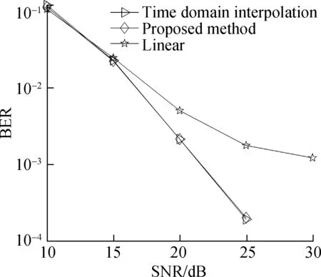
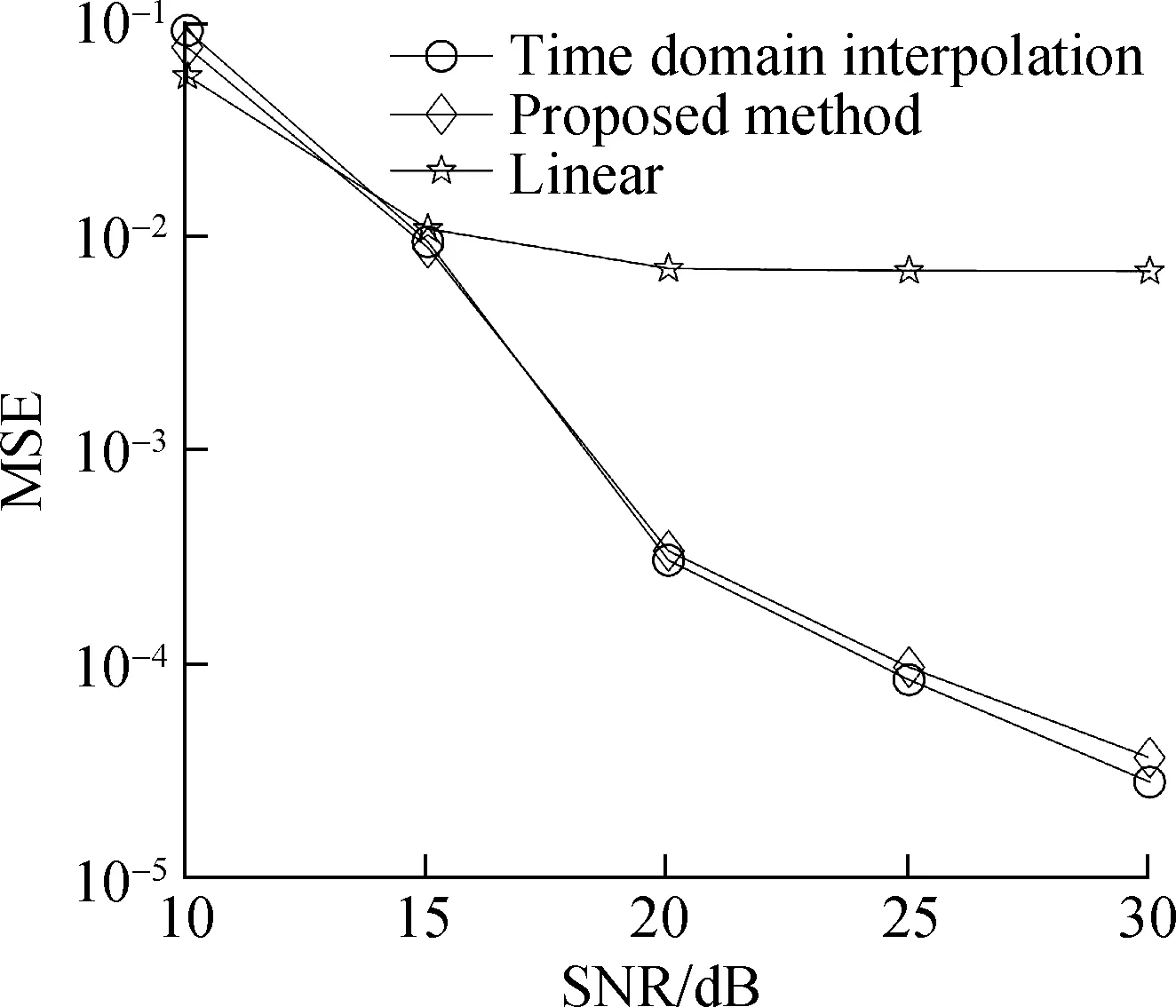
Whenm=4, the time domain interpolation method meets the requirements for use. The legends “time domain interpolation, proposed method, and linear” denote LS channel estimation based on comb-type pilots with time domain interpolation, modified time domain interpolation, and linear interpolation in Fig. 5.
It is obvious that time domain interpolation and the proposed method provide comparable BER and MSE performance, which is significantly better than linear interpolation.

(a)

(b)
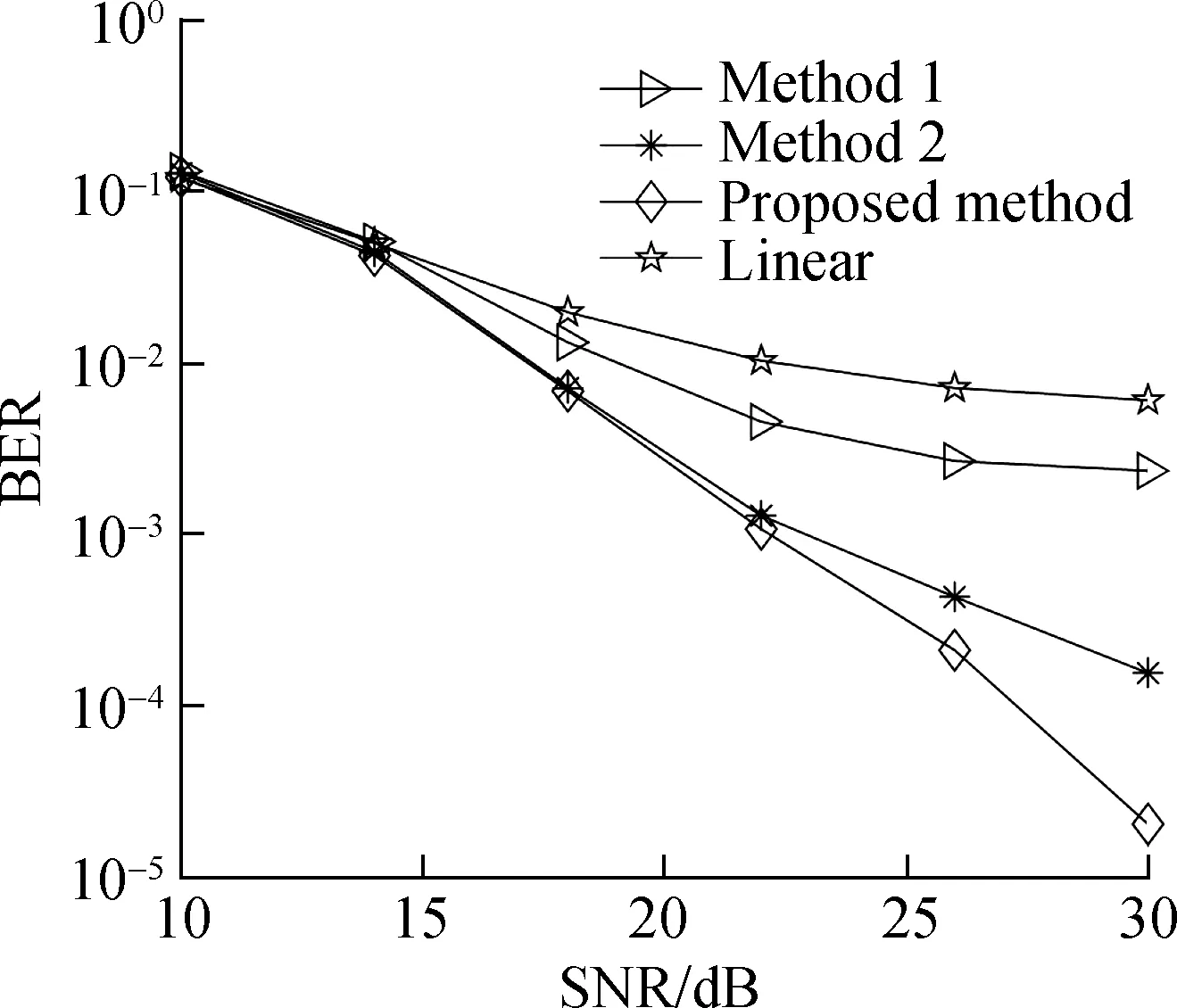
Time domain interpolation cannot be directly used whenm=5 andm=6. The following methods are used to compare with the modified time domain interpolation.


The comparison between modified time domain interpolation, method 1, and method 2 is shown in Figs. 6 and 7. The legends “method 1, method 2, proposed method, linear” denote LS channel estimation based on comb-type pilots with method 1, method 2, the proposed method, and linear interpolation.
In the case of no noise, the CIR calculated by the modified time domain interpolation method (Eq.(26)) and the CIR calculated by performingK-point IDFT on the LS estimated CFR (Eq.(23)) are shown in Tabs. 1 and 2.
It can be seen that

(a)

(b)

(a)

(b)
1)Methods 1 and 2 useK-point IDFT on the LS estimated CFR to calculate CIR; the amplitude of the estimated CIR is relatively accurate, but the phase error is significant and increases as indexnincreases.
2)Methods 1 and 2 outperform linear interpolation, but themK-point DFT andK-point IDFT used do not meet the use conditions of the FFT algorithm (the number of FFT points must be a power of 2). Thus, the amount of calculation is very large. Methods 1 and 2 have low practical value and are only used as comparisons with the proposed method.
3) The modified time domain interpolation method outperforms methods 1 and 2 because it has similar calculation accuracy in the amplitude of the estimated CIR to methods 1 and 2, and the phase error is much smaller, as shown in Tabs. 1 and 2.

Tab. 1 CIR and the estimated CIR by the proposed method and IDFT (m=5)

Tab. 2 CIR and the estimated CIR by the proposed method and IDFT (m=6)
3.4 Computational complexity analysis
In practice, the reciprocals ofPmK,m[n] can be stored, and division in Eq.(26) can be realized by multiplication. Using the proposed method, the computation amount includes three aspects: (N-K)-point linear interpolation,N-point IFFT, and Eq.(26). The computation amount for each step is shown in Tab. 3. (2N-K+(Nlog2N)/2) complex multiplications and (N-K+Nlog2N) complex additions are required. The proposed method has low computational complexity.

Tab. 3 Computation amount of the proposed method
4 Conclusions
1) LS channel estimation based on linear interpolation is theoretically deduced, and the relationship between the estimated CIR from LS based on linear interpolation and the ideal CIR is analyzed.
2) The modified time domain interpolation method is proposed, which uses CIR obtained by LS based on linear interpolation to calculate actual CIR, and interpolation is realized by zero-padding in the time domain, such as time domain interpolation.
3) LS estimations based on comb-type pilots of different pilot spacings with the proposed method, time domain interpolation, and interpolation methods in the frequency domain, such as linear interpolation, cubic interpolation, and cubic spline interpolation, are simulated and compared. The simulation results indicate that the proposed method performs similarly to and outperforms time domain interpolation with low complexity.
4) The proposed method is exempt from the requirement that the number of subcarriers is an integral multiple of pilot spacing. The consumption of subcarriers used for channel estimation can be reduced.
杂志排行
Journal of Southeast University(English Edition)的其它文章
- Improved PBFT protocol based on phase voting and threshold signature
- Predictive current control system of PMSM based on LADRC
- Temperature prediction model for a high-speed motorized spindle based on back-propagation neural network optimized by adaptive particle swarm optimization
- Analysis on resonant shake table with novel variable stiffness mechanism
- BIM-based construction technologies for precast foamed lightweight concrete wallboards
- Analysis on degradation behaviors of sisal fibers at various pH conditions
