Fabrication of segregated poly(arylene sulfide sulfone)/graphene nanoplate composites reinforced by polymer fibers for electromagnetic interference shielding
2022-10-09ChenggongChangJiacaoYangGangZhangShengruLongXiaojunWangJieYang
Cheng-gong Chang ,Jia-cao Yang ,Gang Zhang ,Sheng-ru Long ,Xiao-jun Wang* ,Jie Yang,c
a College of Polymer Science and Engineering,Sichuan University,Chengdu,610065,China
b Analytical and Testing Center,Sichuan University,Chengdu,610064,China
c State Key Laboratory of Polymer Materials Engineering,Sichuan University,Chengdu,610065,China
d Jiangsu JITRI Advanced Polymer Materials Research Institute Co.,Ltd,China
Keywords:Segregated structure EMI shielding Interfacial interaction Mechanical properties
ABSTRACT Poly(arylene sulfide sulfone)/graphene nanoplate (PASS/GNP) composites with segregated structure based on continuous polymer fiber skeletons were fabricated by coating a thin conductive layer on the PASS fibers and then performing compression molding.The formation of a unique segregated conductive network endowed the PASS/GNP composites with high electrical conductivity and excellent electromagnetic interference (EMI) shielding effectiveness(SE),reaching 17.8 S/m and 30.1 dB,respectively,when the content of the GNPs in the conductive layer was 20 wt%.The PASS/GNP composites also exhibited outstanding mechanical properties,which was attributed to the continuous PASS fiber skeletons that could withstand large loads and the strong interfacial interaction between the conductive layers and the PASS fibers that could provide good stress transfer.This approach is suitable for most soluble polymers.
1.Introduction
Nowadays,electromagnetic pollution is very common and cannot be ignored,because it will seriously affect social production activities and threaten human health[1–4].Hence,EMI shielding materials have been widely used to block harmful electromagnetic radiation.Metallic materials were regarded as the best solution for EMI shielding in the past,but problems caused by large density,poor processability and easy corrosion gradually emerged during the application process.In addition,metallic materials with ultra-high electrical conductivity have extraordinary ability to reflect electromagnetic waves,which cause secondary pollution[5–9].Fortunately,conductive polymer composites (CPCs) have shown great prospects for EMI shielding applications[10,11].For conventional CPCs,various conductive fillers (such as carbon nanotubes and graphene)simply fill in the polymer matrix.Satisfactory EMI shielding can only be obtained when the loading of the fillers is high due to the low construction efficiency of the conductive network and the agglomeration of fillers,which will inevitably decrease the processability and mechanical properties of the CPCs[12–15].Therefore,it is necessary to develop CPCs with excellent EMI shielding while reducing the filler content as much as possible.
Unlike conventional CPCs,in which conductive fillers are spread evenly in the whole matrix,emerging CPCs,where the fillers are located at the boundaries of resin micro-regions via a volume exclusion mechanism [16],can form continuous conductive paths more efficiently than conventional CPCs and achieve high EMI shielding at low filler content.For example,the segregated carbon nanotube/polyethylene composites prepared by Jia exhibit a high EMI shielding effectiveness (SE) value of 46.4 dB with just 5 wt%of CNTs[17].Segregated CPCs for EMI shielding have been a research hotspot because of the excellent EMI shielding,but the practical application of segregated CPCs has been limited because the mechanical performance of the segregated CPCs is poor,which is determined by the structure.In the typical segregated CPCs,the resin matrix is segregated into micro-regions linked together by a conductive filler network.The interaction between the conductive network and the polymer micro-regions is weak because of the low processing temperature needed to ensure the restriction of the distribution of the filler [16].
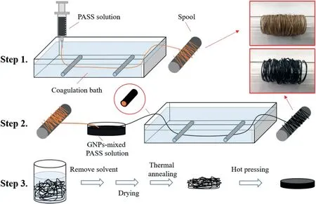
Fig.1.Schematic of the preparation of the PASS/GNP composites with novel segregated structure.
In recent years,much work has been done to improve the mechanical properties of segregated CPCs.One approach is to improve the interfacial interactions between the segregated micro-regions and the conductive network [18–24].For instance,Shi et al.fabricated poly(-l-lactide)/poly(ε-caprolactone)/multiwall carbon nanotube (PLLA/PCL/MWCNT) composites with electrically conductive segregated networks,and the Young's modulus of the segregated CPCs was ca.10%higher than that of pure PLLA[25].
In addition to enhancing the interfacial interaction and reducing the number of weak points,the interface between the filler and the polymer is also expected to improve the mechanical properties.Powders[20–22,25]are typically used for the fabrication of segregated CPCs and a large amount of interfacial area is introduced.Fibers,especially functional fibers [26–28],are an important form of material.Inspired by functional fibers and the idea of reducing the interface in segregated composites,we take fibers instead of powder as the segregated region,reducing much of the interface and potentially improving the mechanical properties.
In this work,poly(arylene sulfide sulfone)/graphene nanoplate(PASS/GNP) composites with a novel segregated structure were fabricated by coating PASS/GNPs on PASS fibers and performing compression molding.PASS is a specific engineering polymer with excellent comprehensive properties,and has proved to be a promising matrix of EMI shielding composites for the harsh environment[24].A conductive coating was deposited through a facile phase separation process,and then thermal annealing reduced the voids in the polymer matrix and strengthened the interfaces between the conductive coatings and the PASS fibers.The PASS/GNP composites exhibited high EMI shielding and enhanced mechanical properties.
2.Experimental data
2.1.Materials
PASS powders were obtained from our laboratory (the inherent viscosity is 0.6 dL/g) [29].GNPs (purity >99%) were purchased from The Sixth Element Co.,Ltd (China).N-Methyl pyrrolidone (NMP,AR grade)was supplied by the Chengdu Kelong Chemical Reagent Factory(China).Conductive silver paint was obtained from Guangzhou Kaixiang Electronics Co.,Ltd(China).
2.2.Preparation of the PASS/GNP composites with segregated structure
Fig.1 shows the fabrication procedure of the PASS/GNP composites with segregated structure.The procedure involves three main steps:preparing PASS fibers by a wet spinning method(Step 1),coating PASS/GNPs on PASS fibers (Step 2) and post-processing and compression molding(Step 3).
Firstly,the wet spinning solution was obtained by adding PASS powders to the NMP and stirring at 180°C for 3 h(the concentration of PASS was 20 wt%).Then,the PASS solution was poured into a syringe and injected into water coagulation liquid at a speed of 30 mL/h after removing air bubbles.PASS fibers could be formed immediately and their diameter could be controlled by changing the inner diameter of the needle(the inner diameter of the needle used in this work was 0.6 mm).Finally,the PASS fibers were collected on a long cylindrical-shaped spool.
The coating of the conductive layer was achieved by precipitating a dilute GNP-mixed PASS solution on the surface of the PASS fibers.Firstly,GNPs were uniformly dispersed in the NMP by ultrasonication for 1 h.Then,the GNP-mixed PASS solution was obtained by adding PASS powders to the suspension and stirring vigorously at 180°C for 1 h(the concentration of PASS/GNPs was 7 wt%).Finally,the continuous PASS fibers prepared by wet spinning passed through the cooled GNP-mixed PASS solution under tractive effort after removing large water droplets on the surface,and then entered a water coagulation bath and were collected on a long cylindrical-shaped spool.
The post-processing was divided into boiling water washing and thermal annealing.Firstly,the PASS fibers coated with a conductive layer were soaked in boiling water for 6 h to remove residual solvent.Then,the fibers were dried in an oven at 100°C for 8 h and annealed at 260°C(approximately 40°C higher than the Tgof PASS) for 1 h to reduce the voids in the polymer matrix and strengthen the interfaces between the conductive coatings and the PASS fibers.Finally,the fiber clusters were compressed into samples at 260°C and 2.5 MPa for 10 min.The PASS/GNP composites with segregated structure were named S-x,where x represents the mass fraction of GNPs in the conductive layer.
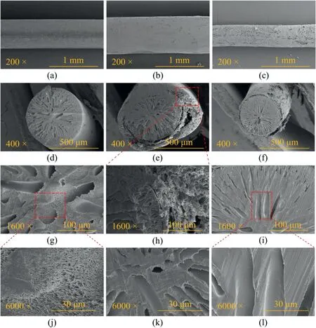
Fig.2.SEM images of the surface of pristine PASS fibers(a)and cross-section(d,g,j),the surface of PASS fibers coated with PASS+10 wt%GNPs(b)and cross-section(e,h,k) before thermal annealing,and the surface of the PASS fibers coated with PASS+10 wt% GNPs (c) and cross-section (f,i,l) after a 1 h thermal annealing at 260 °C.
2.3.Characterization
The morphology and microstructure of the pristine PASS fibers,the PASS fibers coated with a conductive layer and the PASS/GNP composites were characterized by a field-emission scanning electron microscope(FE-SEM)(JSM-7500,JEOL,Japan)at an accelerating voltage of 5 kV.A cross-section of the fiber samples was obtained by cutting with a blade.A cross-section of the composite samples was obtained from brittle fracture after immersing into liquid nitrogen and the tensile test.All samples were sprayed with a gold layer before testing.
The electrical conductivity of the PASS/GNP composites was calculated based on the resistance measured by a digital multimeter (17B,Fluke,USA) at room temperature (23°C) and the dimensions of the samples (13 × 4.0 × 2.1 mm3).Five specimens were tested for each PASS/GNP composite and the results were averaged.Before the test,silver paint was coated on both ends of the specimens and then cured at 100°C for 1 h to eliminate contact resistance.
The EMI shielding of the specimens was evaluated using a vector network analyzer(N5230,Agilent,USA)in X-band(8.2–12.4 GHz),with the sample dimensions of 12 mm in diameter and 2.1 mm in thickness.The reflection coefficient(R),absorption coefficient(A)and transmission coefficient (T) were calculated by the scattering parameters of S11and S21.Total EMI shielding effectiveness (SET),absorption shielding (SEA),and reflection shielding(SER)can further be obtained using the following equations[17].
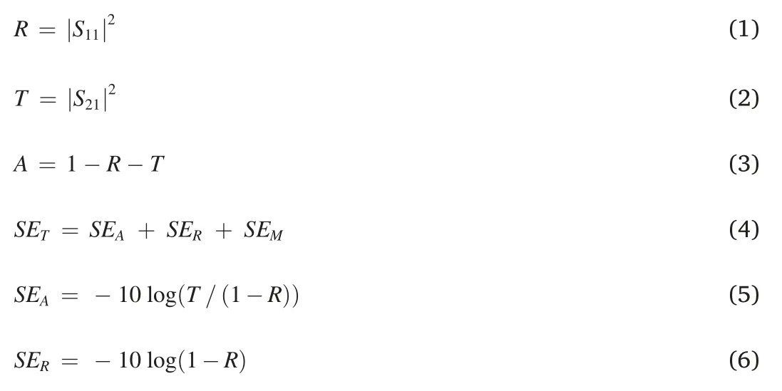
Generally,multiple reflection shielding (SEM) can be ignored when SETis above 15 dB[30].
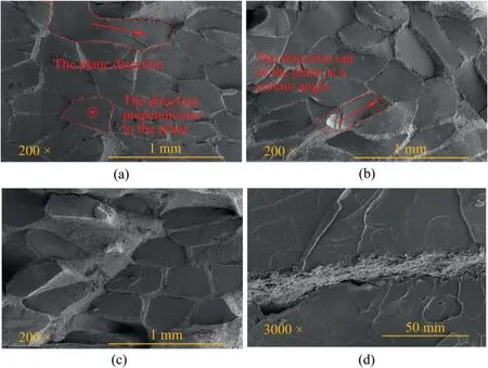
Fig.3.SEM images of the brittle fracture section of S-4 composites (a),S-8 composites (b) and S-20 composites (c,d).
A tensile test was conducted by a universal testing machine (E45,MTS,China)at a strain rate of 5 mm/min and a gauge length of 20 mm.The averaged results were obtained from at least five specimens.
3.Results and discussion
3.1.Morphology of pristine PASS fibers and PASS fibers coated with a conductive layer
Fig.2 shows the morphology of the surface and cross-section of pristine PASS fibers and PASS fibers coated with PASS+10 wt% GNPs.The pristine PASS fibers had a smooth and dense surface (Fig.2a),and cross-section images exhibited a thin top layer and a sponge-like structure with large finger-like cavities(Figs.2d,2g,and 2j)This phenomenon was caused by a typical phase separation process,and since the diffusion rate of the solvent inside the fiber was different,these voids presented a unique shape and distribution [31] The diameter of the fiber increased significantly when the PASS fiber was coated with PASS+10 wt%GNPs,and the surface morphology was relatively rough because the conductive layer contained large amounts of GNPs (Fig.2b).The PASS fibers were not damaged by the solvent during the coating process(Fig.2e).This was because the water existing on the surface and inside of the undried PASS wet-spun fibers could prevent the dissolution and the residence time of the PASS fibers in the mixed-GNPs PASS solution was very short.However,there were still defects among the interphase of the conductive layer and the PASS fiber,and there were a large number of voids in both(Figs.2e,2h,and 2k),which might cause the conductive layer to peel off and the fibers to deform severely during the fabrication of the composites.The diameter of the PASS fibers coated with a conductive layer decreased significantly after thermal annealing because most of the voids were eliminated (Figs.2e,2i,and 2l).In addition,the conductive layer was tightly attached to the surface of the PASS fiber,which proved that the combination of both had become stronger(Fig.2f).
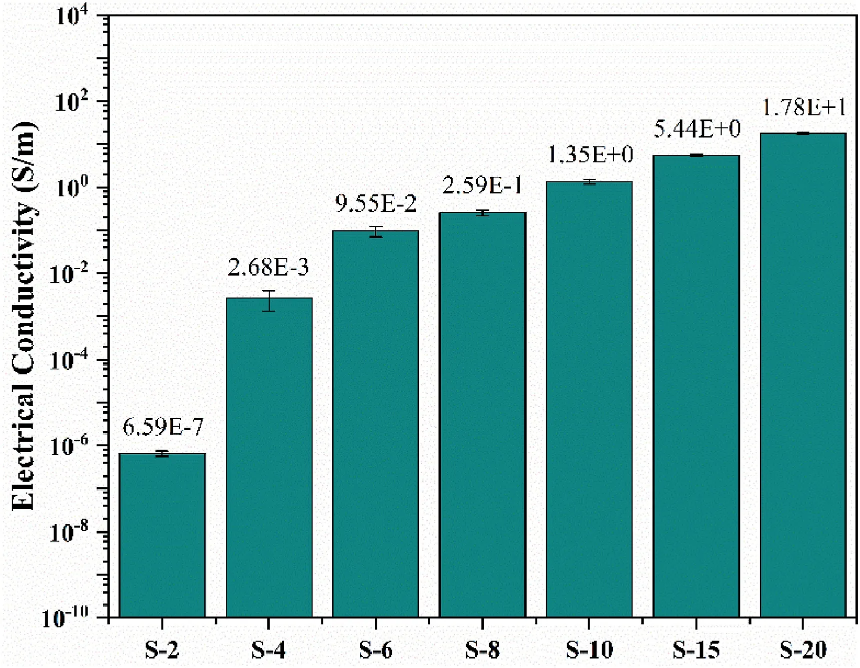
Fig.4.Electrical conductivity of the PASS/GNP composites.
3.2.Morphology of PASS/GNP composites
Fig.3 shows the morphology of the brittle fracture section of the PASS/GNP composites.The PASS/GNP conductive network was located at the interfaces among the PASS fibers,which indicated that the segregated structure was successfully constructed in the PASS/GNP composites(Figs.3a,3b,and 3c).The conductive network was relatively continuous and uniform,which further proved that the special coating process and thermal annealing process made the combination of the conductive PASS/GNP coatings and PASS fibers stronger,and they would not diffuse each other,which was because the PASS had poor fluidity at a temperature only 40°C higher than its glass transition temperature and a small molding pressure.In addition,the polymer fibers were arranged in the plane direction,the direction perpendicular to the plane,and the direction out of the plane at a certain angle in the PASS/GNP composites,which was completely different from the conventional segregated structure (Figs.3a and 3b).No obvious cracks were observed at the interface between the PASS/GNP phase and the PASS fibers (Fig.3d).This phenomenon indicates that extremely high interfacial interaction was achieved when the same resin was used as the matrix,which was very beneficial to improve the mechanical properties of the composites.
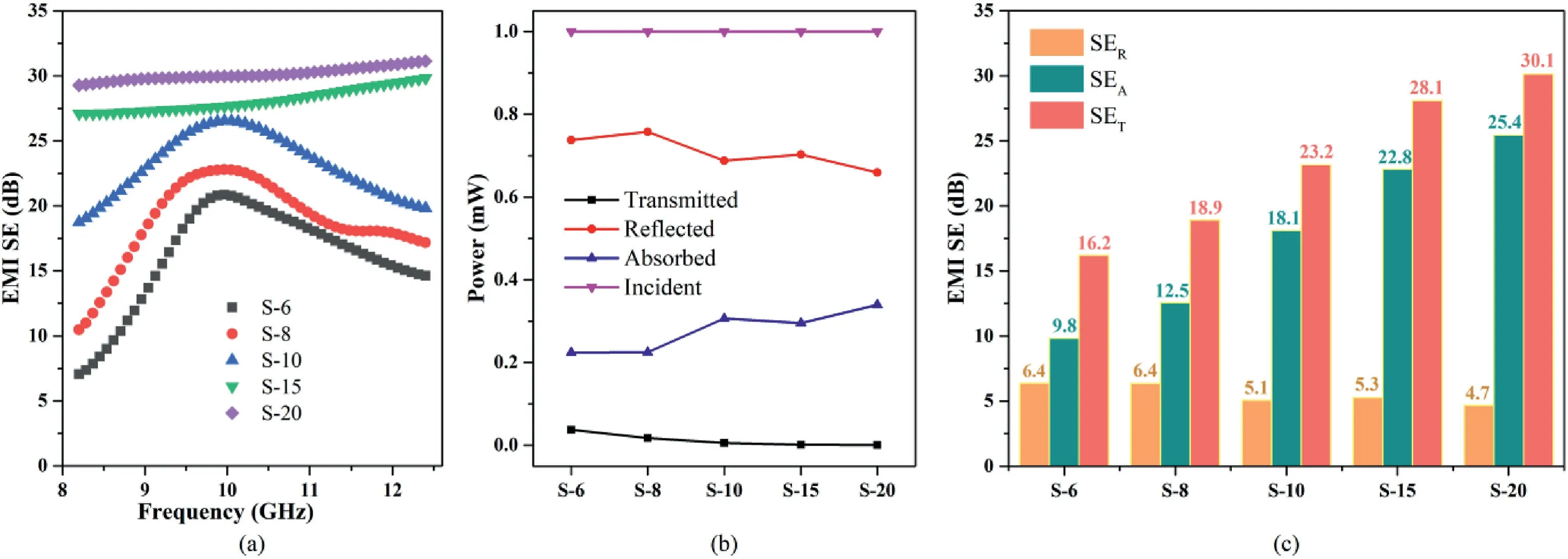
Fig.5.(a)EMI SE of the PASS/GNP composites with various GNP content in the conductive layer as a function of frequency in the X-band;(b)average power balance of different composites;(c) comparison of average SER,SEA,and SET of the PASS/GNP composites.
3.3.Electrical properties of PASS/GNP composites
Fig.4 shows the electrical conductivity of the PASS/GNP composites with various GNP content in the conductive layer.The electrical conductivity of the PASS/GNP composites increased with the increasing GNP content in the conductive layer.According to classical percolation theory,the electrical conductivity of CPCs is very sensitive to the content of conductive fillers in the process of perfecting conductive networks,but after that,the increase rate of the electrical conductivity becomes slower[5].As expected,the S-2 composites exhibited low electrical conductivity,but the electrical conductivity of the PASS/GNP composites was increased by 4 orders of magnitude when the GNP content in the conductive layer reached 4 wt%.The electrical conductivity of the S-10 composites exceeded 1 S/m,which meant that the CPCs could meet commercial requirement,and the electrical conductivity of the S-15 and S-20 composites further increased to 5.44 and 17.8 S/m,respectively.
3.4.Effectiveness of the EMI shielding of PASS/GNP composites
Fig.5a shows the effectiveness of the EMI shielding of the PASS/GNP composites with various GNP content at the frequency range of 8.2–12.4 GHz(X-band).The EMI SE of the PASS/GNP composites increased with the increasing content of GNPs in the conductive layer.For the S-6 composites,the effectiveness of the EMI shielding was about 16.2 dB.The effectiveness of the EMI shielding of the PASS/GNP composites was 18.9,23.3,28.1 and 30.1 dB when the GNP content in the conductive layer was increased to 8,10,15 and 20 wt%,respectively.Especially,for the S-20 composites,at least 99.9%of the electromagnetic waves could be shielded.This trend was consistent with the trend of electrical conductivity of the PASS/GNP composites,suggesting that high electrical conductivity could enhance the ability to attenuate electromagnetic waves.
In order to investigate the EMI shielding mechanism of the composites,the reflected power,transmitted power and absorbed power were first calculated based on the obtained scattering parameters (Eqs.(1)–(3)).The results are shown in Fig.5b.It can be seen that the R is always bigger than A for all composites,indicating that the reflection is the more decisive mechanism due to the impedance mismatch at the interface due to high electrical conductivity [32].This may be due to little power transmitted into the sample as a result of high reflection characteristics.
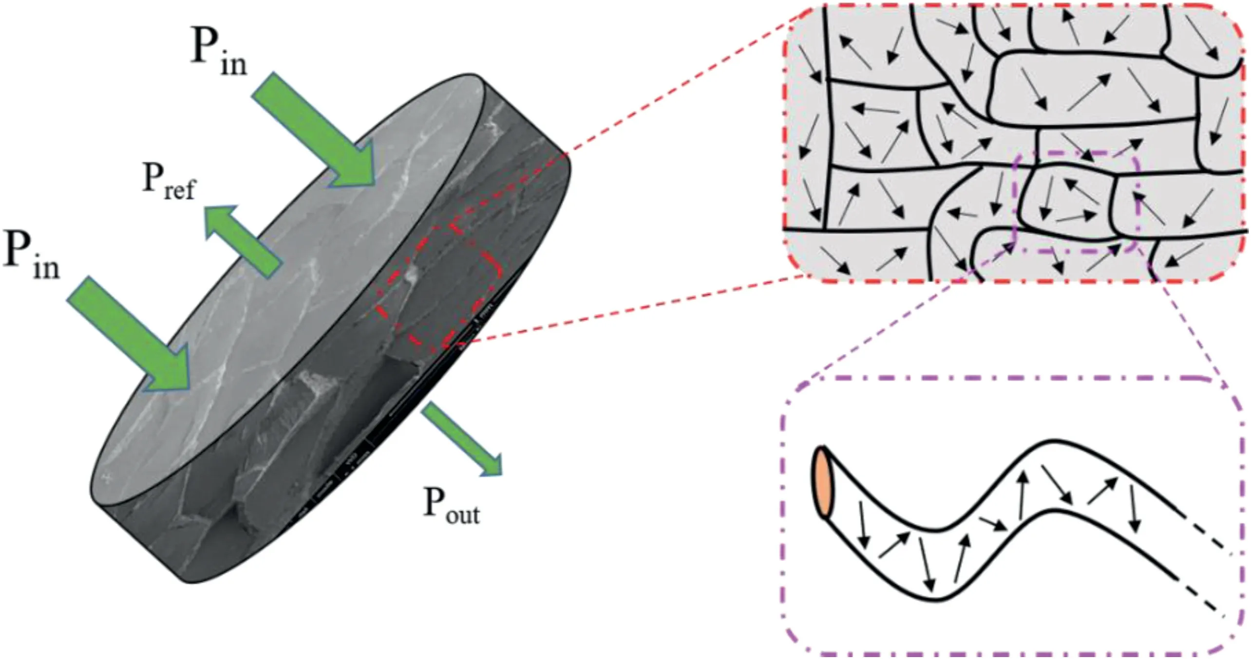
Fig.6.Illustration of attenuation mechanism of electromagnetic waves of the PASS/GNP composites.
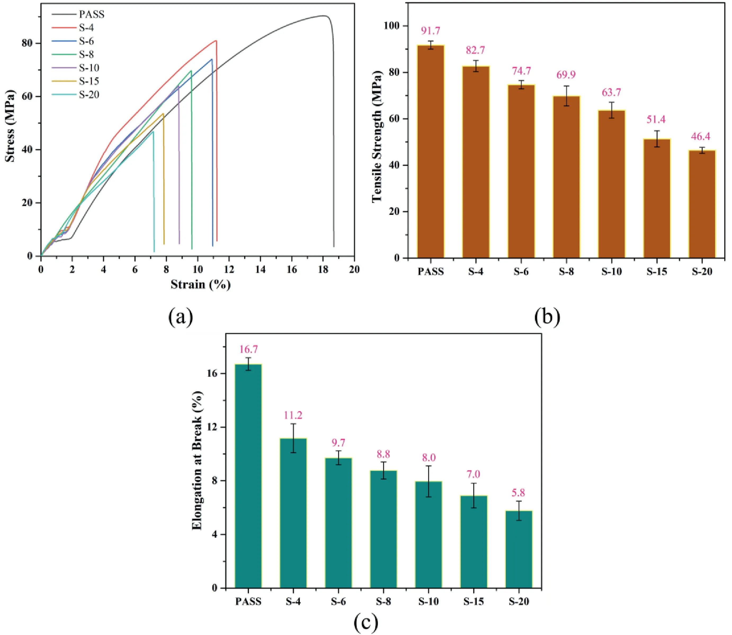
Fig.7.Typical stress–strain curves (a),tensile strength (b) and elongation at break (c) of PASS/GNP composites.
The reflected and absorbed power are quantitative characteristics of power balance when electromagnetic radiation is incident on a shielding material when the EMI SE is a relative quantity and it has nothing to do with the absolute power values [17,32].To further clarify the EMI shielding mechanism of the PASS/GNP composites,the average values of SER,SEAand SETin the X-band were calculated and plotted in Fig.5c.The SERof all specimens exhibited low values below 7.0 dB and showed weak dependence on GNP loading,while SEAgradually increased with the increase of the GNP content in the conductive layer,which meant that the contribution to SETmainly came from SEA.For instance,the SER,SEAand SETof the S-6 composites were 6.4,9.8 and 16.2 dB,respectively.For the S-20 composites,the SERwas only 4.7 dB,but the SEAand SETwere increased to 25.4 and 30.1 dB,respectively.This result indicated that the EMI shielding of the PASS/GNP composites was dominated by microwave absorption.
The electromagnetic shielding capacity originated in its multiscale structure.First,the graphene nanosheets were restricted at the fiber coatings instead of being distributed throughout the entire composites which can contact with each other so that more electrons can overcome the barrier and transport,leading to high capacity of attenuating electromagnetic interference [33].In addition,the defects of graphene nanosheets and interfaces between fillers and matrix provide abundant dipoles,which can also absorb electromagnetic wave[34,35].Third,the conductive coatings can act as an “electromagnetic wire”.The electromagnetic wave would be trapped in the fiber and reflected many times,as illustrated in Fig.6,because of the impedance mismatch between the fiber and the conductive coatings,and finally transferred into heat [28,36,37].
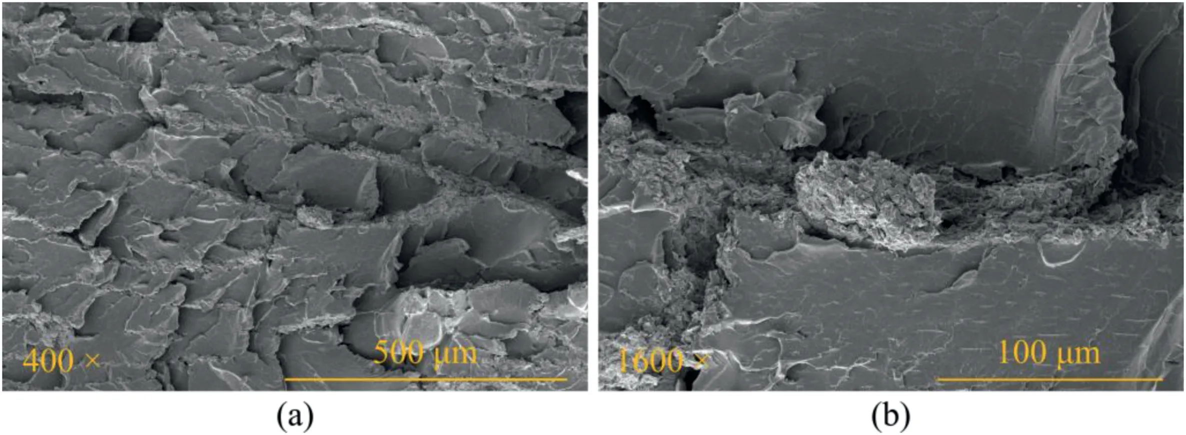
Fig.8.SEM images of the tensile fracture surface of S-6 composite (a) and the magnified micrograph of a (b).
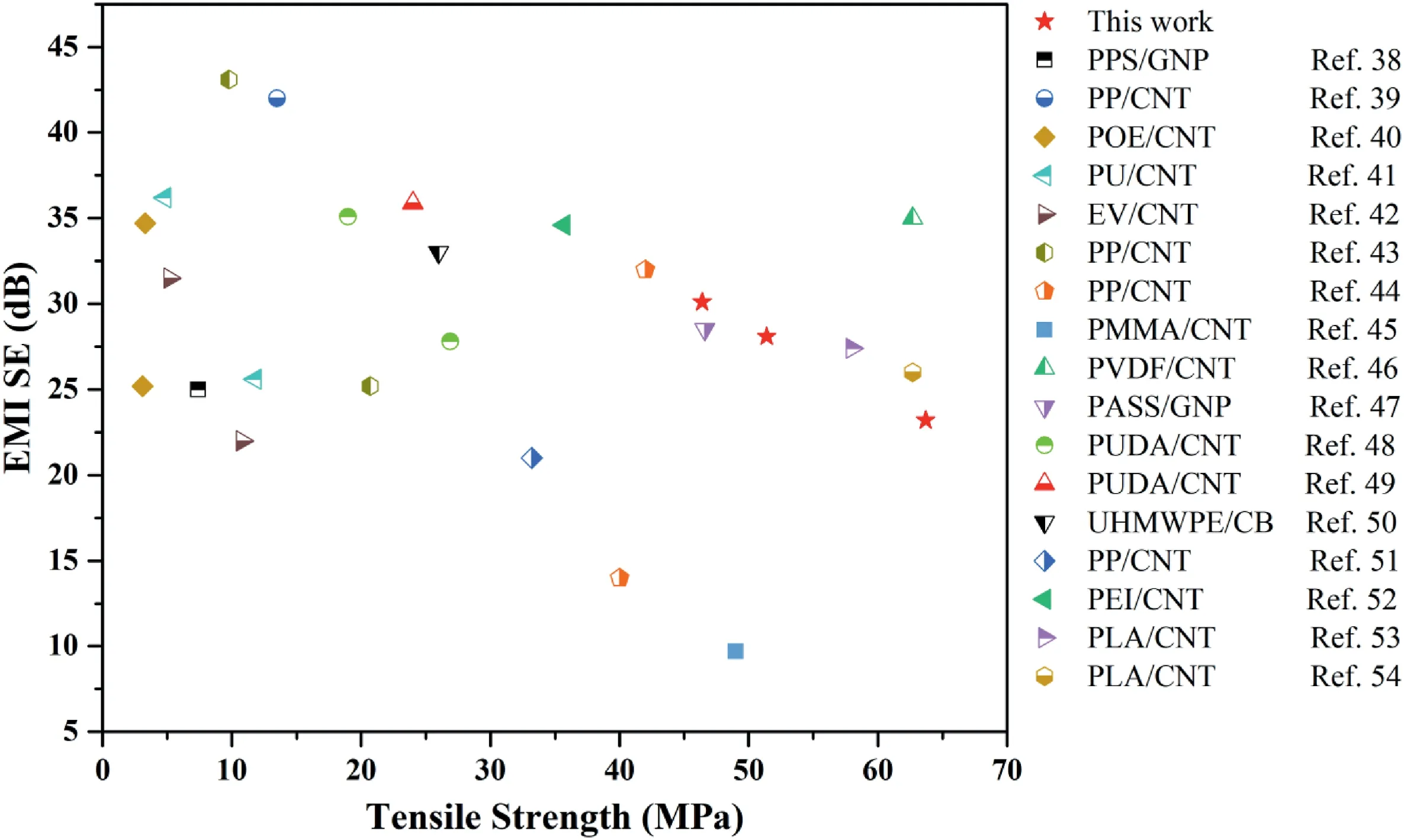
Fig.9.Comparation of EMI SE and tensile strength of our PASS/GNPs composites with carbon-based filler/polymer composites reported in the literature.The thickness of the samples for the electromagnetic interference shielding test is 2.1 ± 0.1 mm.
3.5.Mechanical properties of PASS/GNP composites
High mechanical properties are expected for PASS/GNP composites with a novel segregated structure.Typical stress–strain curves of the PASS/GNP composites are shown in Fig.7a and exhibited a significant trend with increasing GNP content.The tensile strength and elongation at the break are compared in Figs.7b and 7c.It can be clearly observed that the tensile strength and elongation at the break of the PASS/GNP composites decreased with the increasing content of the GNPs in the conductive layer.The tensile strength and elongation at the break of pure PASS were 91.7 MPa and 16.7%,respectively.For the S-4 composites,the tensile strength and elongation at the break were still excellent,reaching 82.7 MPa and 11.2%,respectively.The results proved that the construction of the novel segregated structure will not excessively deteriorate the mechanical properties of the composites.What's more,the tensile strength and elongation at the break of the PASS/GNP composites with novel segregated structure decreased very slowly with the increasing GNP content in the conductive layer.For the S-20 composites,the tensile strength and elongation at the break still reached 46.4 MPa and 5.8%,which were only reduced by 49.4% and 65.3%,respectively,compared with pure PASS.
It has been reported that the construction of conventional segregated conductive networks was very harmful to the mechanical properties of CPCs,and the tensile strength decreased sharply with the increasing content of conductive fillers.To figure out the reasons for the enhanced mechanical performance of the PASS/GNP composites,the tensile fracture surface was observed,as shown in Fig.8.For conventional segregated CPCs,polymer particles were easy to peel off when the composites were under stress due to poor interfacial interaction between the polymer matrix and the fillers.However,the segregated structure was well maintained,and no matter what direction the PASS fibers were arranged along the tensile fracture section,they always tended to break rather than peel off (Fig.8a).In addition,there were no defects at the interface between the PASS fiber and the PASS/GNP conductive layer,as shown in Fig.8b.This phenomenon indicated that the interfacial adhesion between PASS fibers and the conductive layer remained stable even if polymer fibers broke under stress.Therefore,it can be concluded that there are two main reasons why PASS/GNP composites possess excellent mechanical properties: continuous polymer fibers and strong interfacial adhesion.On the one hand,the polymer matrix is interconnected by continuous fibers to form polymer skeletons,which can withstand bigger loads.On the other hand,the introduction of PASS in the conductive layer strengthens the adhesion between the polymer fibers.
Many approaches have been used to improve the performance of the EMI shielding or the mechanical properties of polymer-based composites.The comprehensive comparison of EMI shielding performance and the mechanical properties of many CPCs,including ours,is shown in Fig.9.High EMI shielding effectiveness could be obtained in poly(ethylene-cooctene)(POE)/CNT,polyurethane(PU)/CNT,epoxy vitrimers(EV)/CNT,poly(phenylene sulfide) (PPS)/GNP and polypropylene (PP)/CNT composites,however,the mechanical properties were sacrificed because of high loading of filler or structural defects [38–43].PP/CNT and polymethyl methacrylate (PMMA)/CNT composites possessed enhanced tensile strength,but the effectiveness of the EMI shielding was not satisfactory due to the low electrical conductivity [44,45].Fortunately,CPCs with good EMI shielding performance and mechanical properties have been successfully prepared [46–54].In clear contrast,our PASS/GNP composites exhibited excellent improvement in both EMI shielding performance and mechanical properties.
4.Conclusions
A novel segregated conductive network was constructed in PASS/GNPs composites by coating PASS/GNPs on PASS fibers and performing compression molding.A thin conductive layer was deposited and firmly bonded to the surface of the PASS fiber by phase separation and thermal annealing.We fabricated PASS/GNP composites with different electrical properties and EMI shielding performance by adjusting the content of the GNPs in the conductive layer.For instance,PASS/GNP composites obtained the highest average EMI shielding effectiveness of 30.1 dB in Xband when the content of the GNPs in the conductive layer was 20 wt%,which indicated that at least 99.9% of the electromagnetic waves were shielded.What's more,the PASS/GNP composites exhibited excellent mechanical properties.On the one hand,the polymer matrix was interconnected by continuous fibers to form polymer skeletons in the novel segregated structure,which could withstand a bigger load.On the other hand,a strong interfacial interaction was achieved between the conductive layer and the continuous fiber as the same resin was used in both.We believe that this strategy can promote the application of CPCs with segregated structure.
Declaration of competing interest
The authors declare that they have no conflict of interest.
Acknowledgements
The authors are grateful to the Natural Science Foundation of China(Grant No.21274094,21304060 and 51573103) and the Jiangsu Provincial Key Research and Development Program(Grant No.BE2019008)for providing financial support.
杂志排行
Namo Materials Science的其它文章
- In situ polymerization preparation and mechanical properties of nanocomposites based on PA10T/10I-block-PEG copolymer and graphene oxide
- CNT toughened aluminium and CFRP interface for strong adhesive bonding
- Abnormal enhancement to the quality factors of carbon nanotube via defects engineering
- Fracture behavior of hybrid epoxy nanocomposites based on multi-walled carbon nanotube and core-shell rubber
- Anti-corrosion and electrically conductive inorganic conversion coatings based on aligned graphene derivatives by electrodeposition
- Atomic insights into synergistic effect of pillared graphene by carbon nanotube on the mechanical properties of polymer nanocomposites