Static control method using gradient–genetic algorithm for grillage adaptive beam string structures based on minimal internal force
2022-09-26YanbinSHENHaosongSUNAndongLEIXiaoyuanYINGGuangYANGYaozhiLUO
Yan-bin SHEN, Hao-song SUN, An-dong LEI,2, Xiao-yuan YING, Guang YANG, Yao-zhi LUO
Research Article
Static control method using gradient–genetic algorithm for grillage adaptive beam string structures based on minimal internal force
Yan-bin SHEN, Hao-song SUN1, An-dong LEI1,2, Xiao-yuan YING1, Guang YANG1, Yao-zhi LUO1
1College of Civil Engineering and Architecture, Zhejiang University, Hangzhou 310058, China2China State Construction Engineering (Hong Kong) Limited, Hong Kong 999077, China
The grillage adaptive beam string structure (GABSS) is a new type of smart structure that can self-adjust its deformation and internal forces through a group of active struts (actuators) in response to changes in environmental conditions. In this paper, an internal force control method based on a gradient–genetic algorithm (GGA) is proposed for the static control of a tensioned structure (especially the GABSS). Specifically, an optimization model of the GABSS is established in which the adjustment values of the actuators are set as the control variables, and the internal force of the beam is set as the objective function. The improved algorithm has the advantage of the global optimization ability of the genetic algorithm and the local search ability of the gradient algorithm. Two examples are provided to illustrate the application of the GGA method. The results show that the proposed method is practical for solving the internal force control problem of the GABSS.
Grillage adaptive beam string structure (GABSS); Gradient–genetic algorithm (GGA); Structural control; Adaptive structure; Actuator
1 Introduction
Spatial structures have become more lightweight and efficient, resulting in the emergence of adaptive structures. An adaptive structure is based on the idea that the behavior of a structure is not established during the initial design phase and the structural response is controlled continuously in a predesigned and beneficial manner (Korkmaz, 2011). An adaptive structure can monitor and self-adjust its working status according to environmental conditions through the integration of sensing and active components. Adaptive structures are widely used to manipulate internal stresses and displacements and to control vibrations (Venanzi, 2016). In recent years, most studies on adaptive structures have focused on vibration control. Various types of devices have been used, such as active mass dampers (Bailey and Ubbard, 1985), magneto-rheological dampers (Cha and Agrawal, 2013a, 2013b), concentrically braced frames (Li and Fahnestock, 2013; Li et al., 2013), and active vibration isolation (Hoque et al., 2011; Yun and Li, 2011; Li et al., 2012; Sun et al., 2014; Xu and Sun, 2015). However, the study of the control of adaptive structures (Li and Wang, 2015; van Bommel et al., 2016) using static characteristics (e.g., deformation and internal force) has been relatively limited.
A beam string structure (BSS) is a hybrid tension structure consisting of an upper beam (or truss), a lower cable, and a vertical link strut. The upper beam and the lower string work together to reduce the stress and deformation of the beam effectively by applying a prestress. The BSS exhibits good mechanical behavior owing to the full use of rigid and flexible materials and has wide applications with the additional advantages of beautiful form and convenient construction. Most conventional BSSs are unidirectional, and are formed by the parallel arrangement of a single BSS through a longitudinal bracing cable. Grillage beam string structures (GBSSs) are formed by intersecting the BSS in two orthogonal directions, and radiated beam string structures (RBSSs) are formed by placing the beam radially from the center when the struts are connected to a loop or diagonal cable. Compared with unidirectional BSSs, GBSSs and RBSSs can provide more space and better out-of-plane stability. Thus, they have been widely used in engineering designs, such as the National Indoor Stadium and Table-Tennis Gymnasium for the Beijing Olympic Games in China.
The vertical link strut plays an important role in the BSS despite its light internal force. A slight change in the strut length can lead to stress redistribution in the entire structure. Using the vertical strut as an adjustable component, the traditional BSS becomes an adaptive structure with self-adjustment ability. This is called an "adaptive beam string structure" (ABSS). By using a control system consisting of two basic modules (sensors on the beam and actuators on the struts), the ABSS has better working performance and a stronger environmental adaptability than the traditional BSS.
The ABSS is a new type of adaptive structure and little work has been done on it. Similar studies on other adaptive structures have been reported, including tensegrity, cable domes, and trusses. A multi-objective shape optimization control model with a reinforcement-learning process (Adam and Smith, 2007, 2008) was proposed for a five-module tensegrity and the control framework was validated experimentally on an active tensegrity structure. A newly deve loped Levy form adaptive cable dome (Kmet and Mojdis, 2015), which can alter its stiffness configuration and stress properties, has been described adapting its behavior to current loading conditions. To verify the superiority of the adaptive truss structure in terms of building energy consumption and structural performance under linear and nonlinear conditions, an active control optimization model of truss structures (Senatore et al., 2013, 2018a, 2018b), based on a sequential quadratic programming algorithm, was built. For BSSs, the structural displacement was set as the control objective to study the two-strut BSS control problem (Sobek and Teuffel, 2001). The hydraulic cylinder was set as the strut (Noack et al., 2006) to change the shape of the BSS, and the displacement control strategy of a one-strut BSS under a moving load was studied from theoretical and experimental perspectives.
The above studies focused on a unidirectional BSS with a small number of active components so that an exhaustive algorithm could obtain the optimal solution that effectively leads the structure to the control target. In addition, in a previous study, it was proved that a unidirectional ABSS has better adaptivity and capability than an uncontrolled one. As the structural span increases, the feasible space of the control instructions increases significantly while traditional algorithms seem to be less applicable owing to their limitations of efficiency and time. Therefore, it is necessary to develop a large-space random search algorithm to solve this problem effectively and efficiently (Xu and Luo, 2009). A static displacement control model of a unidirectional BSS (Shen et al., 2013) was developed in which a simulated annealing algorithm was used to calculate the adjustment values of the struts by taking the structural displacement as the control objective. The traditional random search algorithm converges slowly and is less efficient, which highlights the need to develop an algorithm with a high local and global search efficiency.
In this study, an algorithm was developed for the active control of a grillage adaptive beam string structure (GABSS), which combined the genetic algorithm (GA) and the gradient algorithm as a gradient–genetic algorithm (GGA). This algorithm is also suitable for the static control of other tensegrity structures but it has a greater advantage in multivariable calculations in large spaces, such as grillage beam string structures and suspend-domes. The GABSS internal force control model was established by considering the elongation of the actuator as the control variable and the internal force as the control target. The GGA was used to search for the optimal elongations of the actuating struts. Several examples were used to verify the effectiveness of this method for the active control of GABSSs.
2 Optimization model of internal force control for GABSSs
To control a GABSS, as shown in Fig. 1, the following underlying assumptions are set:

Fig. 1 Diagram of a GABSS
(1) The joints connecting the cable and strut are hinges.
(2) The weight of the structure is converted into equivalent dead loads on the beam.
(3) The plane load of the GABSS is converted into a beam load.
Currently, in the active control process of the tensegrity structure, most actuators use electric push rods to realize the expansion and contraction of struts with discrete steps. As shown in Fig. 2, the extendable rods travel a certain distance when the motor rotates once. In this study, the electric push rod produced by Lim-Tec Transmission Equipment Co., Ltd., China, model LAP25, was used. Its relevant parameters are a rated load of 2000 N, a worm gear reduction ratio of 1:10, and a rated stroke of 200 mm.
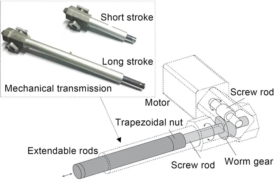
Fig. 2 Electric push rod structure diagram
In the BSS system, the cables and struts are set to improve the performance of the upper beam; thus, the working state of the upper beam can be considered the working state of the entire structure. To measure the stress state of the GABSS precisely each upper beam is divided intosections. The internal force coefficientof the upper beams is defined as:
(1)
(2)
The working state coefficient of the whole structure is defined as:
(3)
The internal force optimization model of a GABSS is
(4)
The control optimization process in Eq. (4) is performed using the GGA described in the next section.
3 Internal force control through the gradient–genetic algorithm
The GA is a widely used random search algorithm inspired by the natural selection and genetic mechanisms of biology (Sampson, 1976). Specifically, the initial population is generated randomly and a new solution is generated by selecting, crossing, and mutating. The principle of proportional selection is typically used to calculate a selection operator. The main idea is that individuals with high fitness values have a high probability of selection. Then, if the pro bability of an individual selection is:
(5)
whereandFare the population size and the fitness value of theth individual, respectively.
Then each individual in the population represents a solution to the problem, and the solution is measured using a fitness function. Individuals with higher fitness values have a greater probability of forming the next-generation population by crossing and mutating. When the number of final iterations is reached or the results converge, the obtained individual is determined to be the optimal solution to the problem.
The GA has excellent global search capabilities, but it may be less efficient in the local search area.
The gradient descent method is a descent method based on the minimization of the negative gradient direction of the objective function, as shown in Fig. 3. The linear search is performed first at the initial iteration point, and then the step sizeand gradientare obtained. The position of the initial point is updated as
(6)
Fig. 3 Schematic diagram of gradient descent method
The gradient descent algorithm obtains the local optimal point near the iterative point more quickly and easily. However, this method fails to find other local optimal solutions away from the current location for an optimization problem with many local optima. So it is difficult to find a global optimal solution using the gradient descent algorithm.
To optimize the working state of the GABSS, an improved GA, the GGA, was developed. It has the global search ability of the GA and the local search ability of the gradient algorithm. The gradient algorithm is used to improve the local search ability, convergence speed, and search precision of the new algorithm, whereas the GA improves the diversity of the population by crossing and mutating. This new GGA method combines the advantages of the GA and the gradient algorithm to achieve global optimization.
The GGA process is as follows. First, the gradient operator is introduced into the GA; then, the result of the GA is taken as the initial value after a certain number of evolutions. Subsequently, local optimization is carried out using the gradient algorithm, and the optimal value of the search is compared with the optimal value of the GA. A better result is set as a new generation of individuals. The GGA has five steps.
Step 1: The initial population is randomly gene rated using real coding, and each chromosome is a real vector.
Step 2: The evolution process=1 is initiated, and the fitness value corresponding to each elongation group is calculated. The fitness function is used to distinguish the quality of the individual, generally transformed by the objective function.
Step 3: Choosing, crossing, and mutating operations are used to generate a new generation of groups.
Step 4: It is determined whether the gradient algorithm needs to be optimized. If so, the gradient algorithm is used for the local optimization of the new offspring population and the superior offspring is used to replace the parent to join the new population.
Step 5: It is determined whether the termination conditions are met. If so, the optimal solution is returned; otherwise,=+1 and go to Step 2.
The flowchart of GGA for control of the GABSS is shown in Fig. 4.
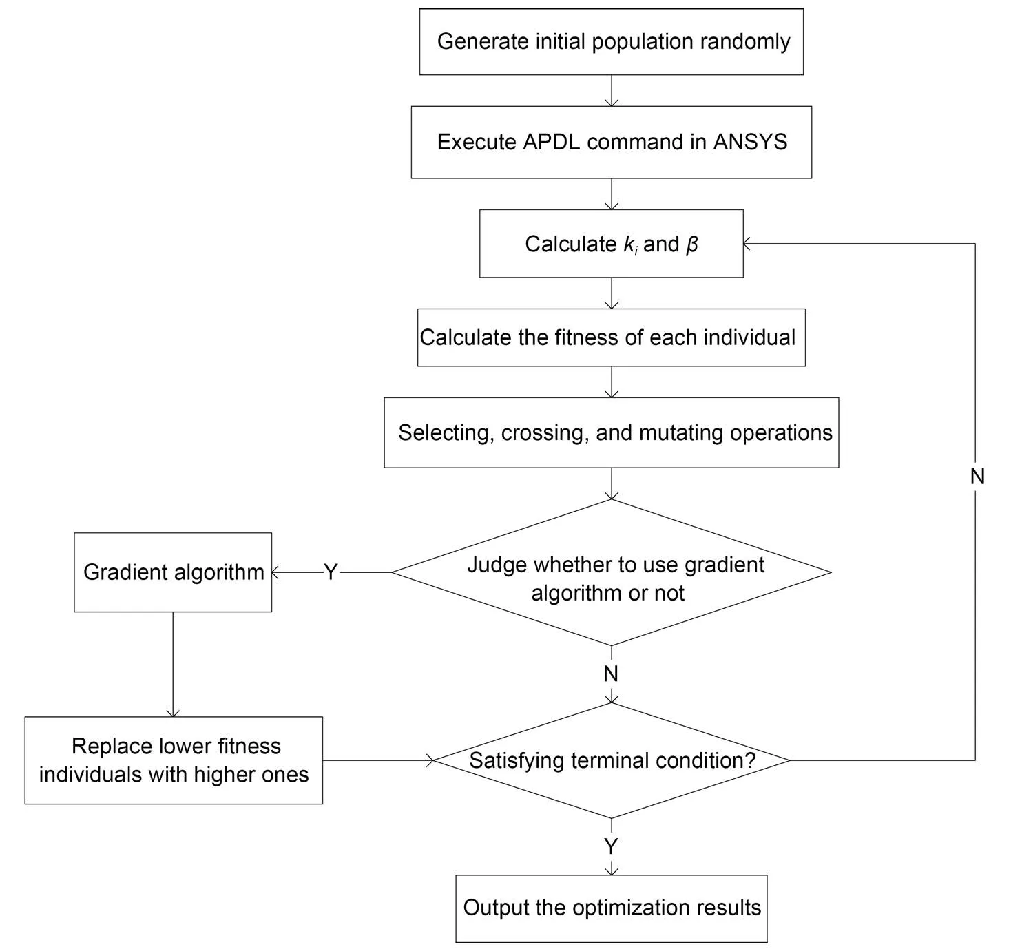
Fig. 4 Flowchart of GGA for control of GABSS. kiand β are the internal force coefficient and the working state coefficient of the whole structure, respectively. APDL means ANSYS parametric design language
4 Example 1
A conventional 2×2 orthogonal tension beam with a span of 24 m in both the- and-directions was considered as an example to verify the control algorithm, as illustrated in Fig. 5. To make the structure reach a state of large deformation and critical failure internal force under the uncontrolled load case, the relevant parameters were set after a set of trial calculations.
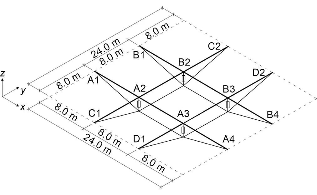
Fig. 5 Schematic diagram of GABSS. A1, A2,···, D2 are the node numbers of the upper beam section of the GABSS
The inverted rise is 2.4 m, to make the height to span ratio reach 1/10. The cross-section of the four crossing straight beams is a square steel tube with dimensions of 150 mm (width)×300 mm (height)×15 mm (thickness). The four active struts are circular pipes with a cross-sectional area of 1200 mm2. The cable consists of six steel wires with a diameter of 12.7 mm.
The elasticity modulus of the beam and struts is 2.06×10⁵N/mm2, and the elasticity modulus of the cable is 1.95×10⁵N/mm2. The constraint conditions are listed in Table 1.
For the roof structure, there are usually four types of external load: the dead load=4 kN/m, the full-span live load1, the half-span live load2, and the upward wind load. Three typical load cases are considered: Load case 1, 1.0+1.01; Load case 2, 1.0+1.02; Load case 3, 1.0+1.0. A load distribution diagram is shown in Fig. 6.
4.1 Load case 1
The ultimate load of1for the uncontrolled GBSS is calculated as1=4.65 kN/m, and the results of the uncontrolled (before control, BC) GABSS, the linear force control (LFC), the nonlinear force control (NFC, when geometric nonlinearities of large deformations are considered), and the traditional GA (NFC) are shown in Table 2.
Table 2 demonstrates that, under Load case 1, the working state coefficients of the GBSS after LFC and NFC decreased by 20.15% and 19.71%, respectively, using the GGA. The maximum displacements of the beam were significantly reduced, decreasing by 82.57% and 83.12%, respectively. The results of LFC and NFC were very close, which shows that the beam was in a small deformation state during the control process and thus the influence of geometric nonlinearity was extremely small and could be ignored. The results for the GGA were superior to those of the traditional GA. This may be because the traditional GA has poor local search performance and is prone to premature situations; the gradient algorithm was added to improve that.
The convergence trends of the GGA and GA vary with the algebra, as shown in Fig. 7. In the fourth-generation population for the gradient search, the objective function quickly converges to the optimal value, proving the efficiency and stability of the algorithm.

Table 1 Constraint conditions for the static control of GABSS (Example 1)

Fig. 6 Schematic diagram of load distribution: (a) full-span variable live load Q1; (b) half-span variable live load Q2; (c) wind load W

Table 2 Results under Load case 1 of the GBSS (Q1=4.65kN/m)
The displacement change of the beam is shown in Fig. 8, and the change in the bending moment is shown in Fig. 9. The geometrical shape of the beam is improved when the internal force of the beam is reduced, which is of great significance for the GBSS.
The ultimate load of1for the GABSS is calculated as1=20.5 kN/m, and the results are shown in Table 3. In other words, the load capacity of GABSS increased by up to 340.86% after NFC. It can significantly improve the bearing capacity of the BSS, thus providing better environmental adaptability. Comparing Tables 2 and 3 reveals that the ultimate bearing capacity of the GBSS is controlled byof the upper beam under the action of a full-span uniform live load, whereas the bearing capacity limit of the GABSS is controlled byand the range of the actuator elongation. The bearing capacity of the materials can be fully utilized after control.
4.2 Load case 2
The ultimate load of2for the uncontrolled BSS is calculated as2=4.97 kN/m, and the results of the uncontrolled GABSS, LFC, and NFC are shown in Table 4. Similar to Load case 1, the effect is significant after control. The displacement change in the beam is shown in Fig. 10, and the change in bending moment is shown in Fig. 11.
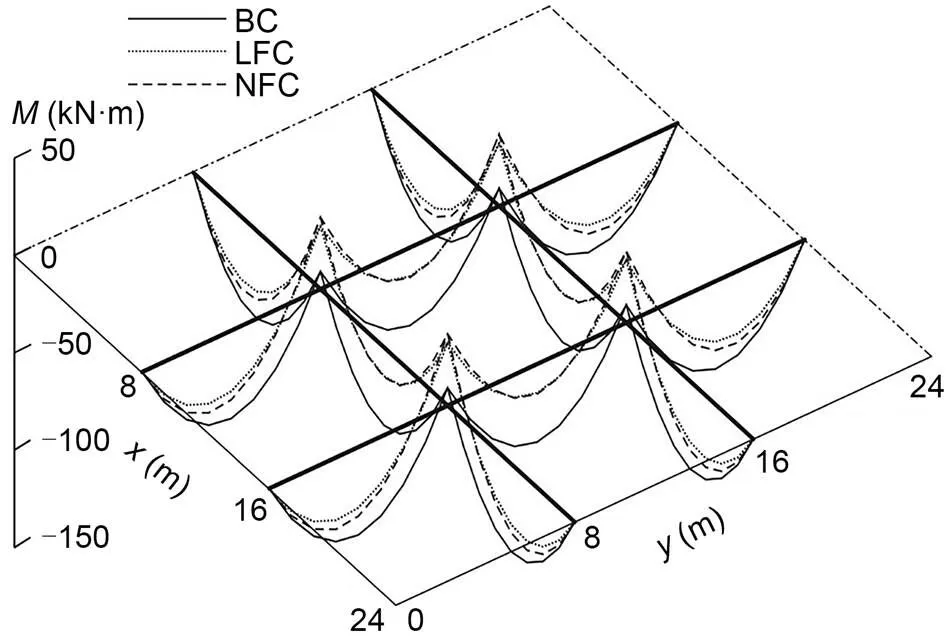
Fig. 9 Bending moment (M) change of GABSS under Load case 1
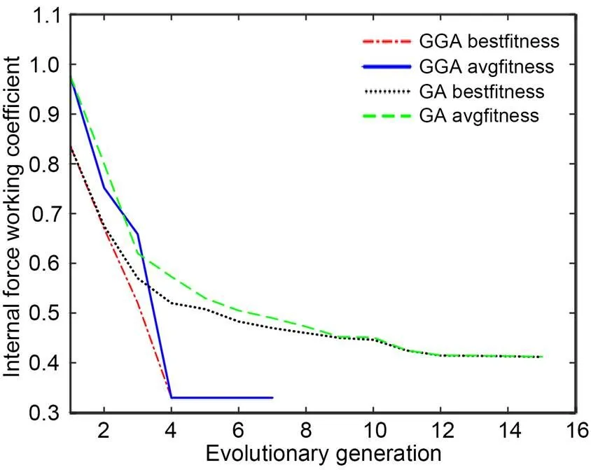
Fig. 7 Convergence trends of GGA and GA
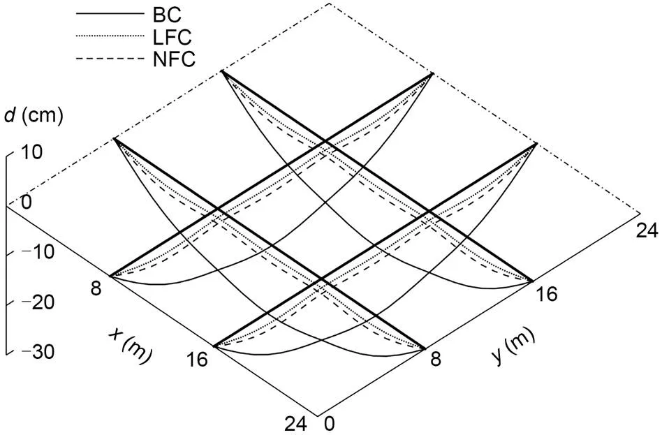
Fig. 8 Displacement (d) change of GABSS under Load case 1

Table 3 Results under Load case 1 of the GABSS (Q1=20.5 kN/m)

Table 4 Results under Load case 2 of the GBSS (Q2=4.97 kN/m)
*The load capacity is controlled by this independent variable

Table 5 Results under Load case 2 of the GABSS (Q2=18.18 kN/m)
*The load capacity is controlled by this independent variable
As shown in Figs. 8 and 9, when geometric nonlinearity is considered, the redistribution of displacement and bending moment of beams C1, C2 and D1, D2 is better.
The ultimate load of2for the GABSS is calculated as2=18.18 kN/m, and the results are listed in Table 5.
The load capacity of the GABSS improved by 265.79% after NFC. The ultimate bearing capacity of the GABSS is controlled byof the upper beam under the action of a full-span uniform live load, whereas the bearing capacity limit of the GABSS is controlled byand the range of the actuator elongation.
4.3 Load case 3
The ultimate loads offor the uncontrolled BSS and the GABSS are calculated as 2.90 and 3.49 kN/m (increase of 20.34%), respectively and the results are shown in Table 6. The changes in the displacement and bending moment of the beam are shown in Fig. 12.
Before the regulation, the cable of the GBSS was slack. Through the NFC, the cable becomes tight under the action of the wind load, thus ensuring that all components of the structure work together to achieve better performance.
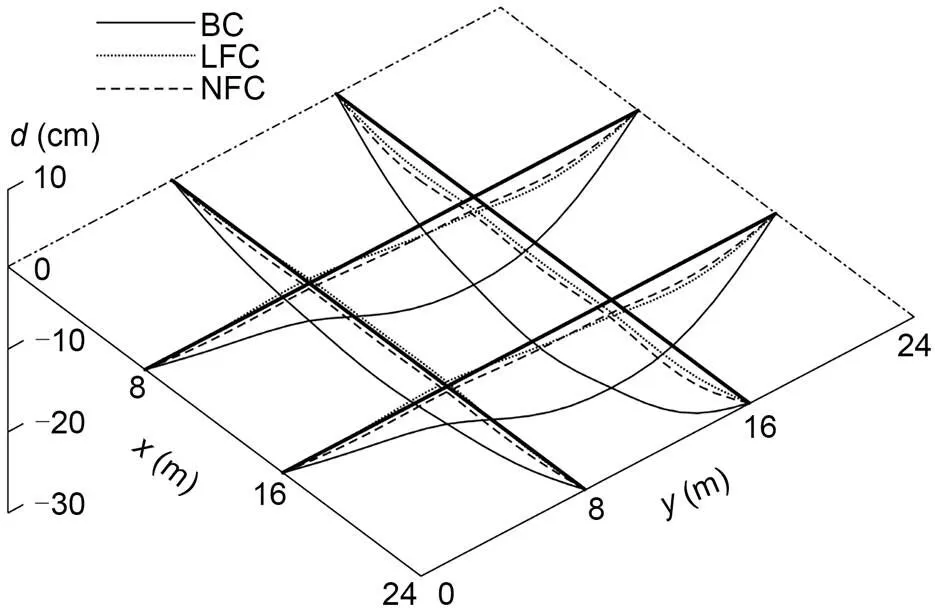
Fig. 10 Displacement change of GABSS under Load case 2
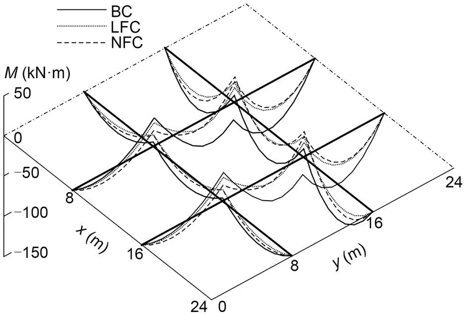
Fig. 11 Bending moment change of GABSS under Load case 2
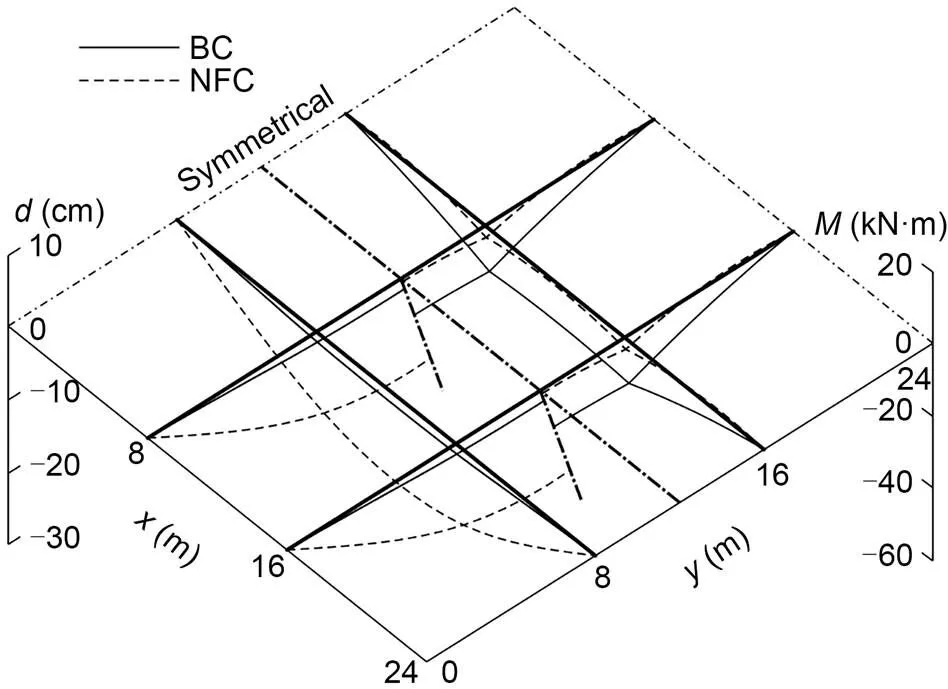
Fig. 12 Displacement and bending moment changes of the GABSS under Load case 3
5 Example 2
As the structure becomes complex, the feasible space of the control solution increases owing to the increasing number of active struts. Therefore, the effectiveness and efficiency of the control algorithm must be verified. As a result, a more complex GABSS model with 3×3 crossing beams was established as shown in Fig. 13. It was the same as in Example 1, except that the inverted rise was 3.2 m. The constraint conditions are listed in Table 7. Example 2 was much more indeterminate and complicated, with six prestressed cables and nine active struts. However, the operation time did not increase much compared with Example 1, which verified the high efficiency and fast convergence speed of the GGA.

Table 6 Results under Load case 3 of the GABSS
*The load capacity is controlled by this independent variable
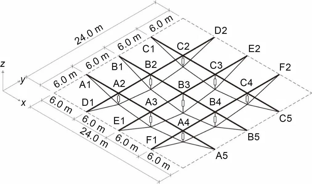
Fig. 13 Schematic diagram of GABSS
Similarly, four types of external load and three typical load cases were considered. A load distribution diagram is shown in Fig. 14.
5.1 Load case 1
The ultimate load of1for the uncontrolled BSS is calculated as1=5.5 kN/m, and the results of the uncontrolled GABSS and NFC are shown in Table 8. The displacement change of the beam is shown in Fig. 15, and the change in bending moment is shown in Fig. 16.
The ultimate load of1for GABSS is calculated as1=19.27 kN/m (an increase of 250.36%), and the results are shown in Table 9.
5.2 Load case 2
The ultimate load of2for uncontrolled BSS is calculated as2=2.4 kN/m, and the results of the uncontrolled GABSS and NFC are shown in Table 10.
Similar to Load case 1, the effect is significant after control. The displacement change of the beam is shown in Fig. 17, and the change in bending moment is shown in Fig. 18.

Fig. 14 Schematic diagram of load distribution: (a) full-span variable live load Q1; (b) half-span variable live load Q2; (c) wind load W

Table 7 Constraint conditions for the static control of GABSS (Example 2)

Table 8 Results under Load case 1 of the GBSS
*The load capacity is controlled by this independent variable

Table 9 Results under Load case 1 of the GABSS
*The load capacity is controlled by this independent variable

Table 10 Results under Load case 2 of the GBSS
*The load capacity is controlled by this independent variable
The ultimate load of2for GABSS is calculated as2=10.87 kN/m (an increase of 352.92%), and the results are listed in Table 11.
5.3 Load case 3
The ultimate loads offor the uncontrolled BSS and the GABSS are calculated as 3.40 and 3.53 kN/m (an increase of 3.8%), respectively. The results are shown in Table 12. The displacement change in the beam is shown in Fig. 19. The change in bending moment is shown in Fig. 20.

Fig. 18 Bending moment change of GABSS under Load case 2

Fig. 19 Displacement change of GABSS under Load case 3
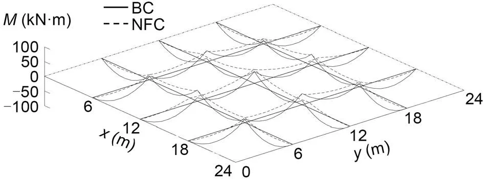
Fig. 20 Bending moment change of GABSS under Load case 3
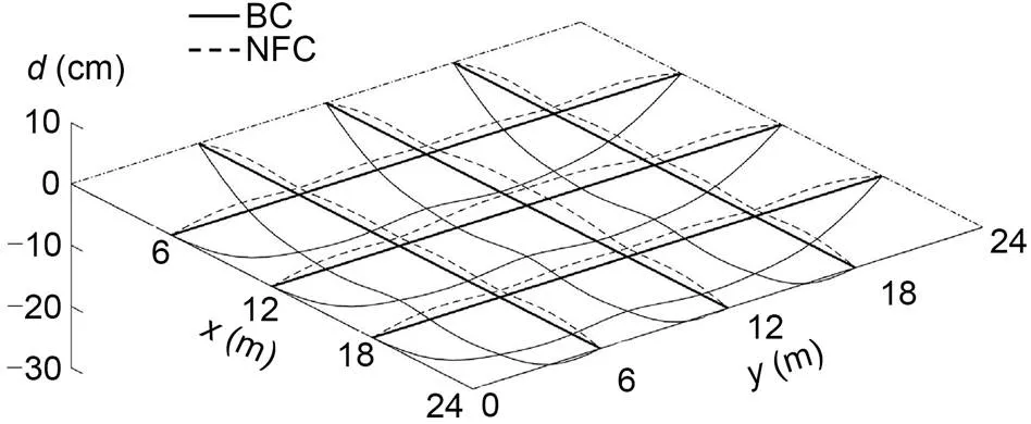
Fig. 15 Displacement change of GABSS under Load case 1
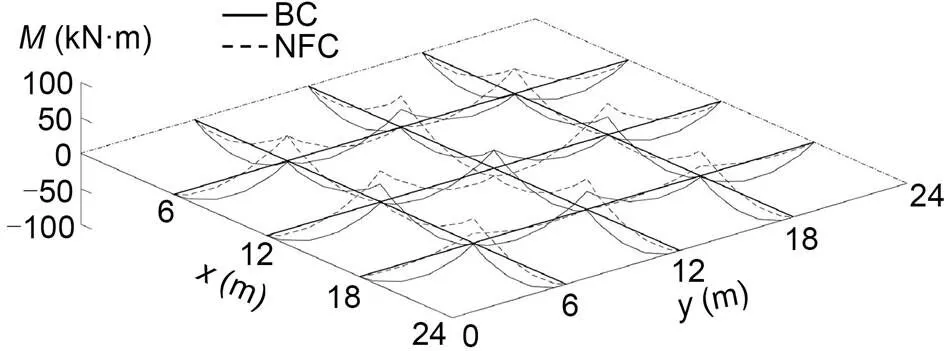
Fig. 16 Bending moment change of GABSS under Load case 1
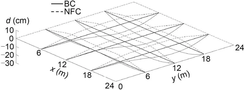
Fig. 17 Displacement change of GABSS under Load case 2

Table 11 Results under Load case 2 of the GABSS
*The load capacity is controlled by this independent variable

Table 12 Results under Load case 3 of the GABSS
6 Conclusions
A new GGA was proposed in which a gradient operator is introduced into the traditional GA. A static control method for a GABSS was developed, and an optimization model was established using the GGA. Two examples were provided to verify the feasibility and effectiveness of the GGA method. The conclusions of this study are summarized as follows:
(1) The GGA method has a good local search ability, global optimization ability, and fast convergence speed. The results of the examples show that this method has good adaptivity and can help solve the internal force control problem of the GABSS.
(2) Compared with the traditional GBSS, the load-bearing capacity of the GABSS with a static control system is increased significantly under the three designed load cases. Specifically, when the structure is subjected to a downward load, the actuator range is larger, and the ultimate bearing capacity of the structure increases.
(3) The wind load is unfavorable to the BSS because the cable has a risk of slack. After structural active control is performed in the GABSS, the tension of the structural cable can be obtained, and all the components of the structure can work together to achieve better performance.
This work is supported by the National Key R&D Program of China (No. 2017YFC0806100) and the National Natural Science Foundation of China (No. 51578491).
Yan-bin SHEN designed this study. Guang YANG and An-dong LEI processed the corresponding data. Xiao-yuan YING wrote the first draft of this manuscript. Yao-zhi LUO helped to organize the manuscript. Hao-song SUN revised and edited the final manuscript.
Yan-bin SHEN, Hao-song SUN, An-dong LEI, Xiao-yuan YING, Guang YANG, and Yao-zhi LUO declare that they have no conflict of interest.
Adam B, Smith IFC, 2007. Self-diagnosis and self-repair of an active tensegrity structure., 133(12):1752-1761. https://doi.org/10.1061/(ASCE)0733-9445(2007)133:12(1752)
Adam B, Smith IFC, 2008. Active tensegrity: a control framework for an adaptive civil-engineering structure., 86(23-24):2215-2223. https://doi.org/10.1016/j.compstruc.2008.05.006
Bailey T, Ubbard JE, 1985. Distributed piezoelectric-polymer active vibration control of a cantilever beam., 8(5):605-611. https://doi.org/10.2514/3.20029
Cha YJ, Agrawal AK, 2013a. Decentralized output feedback polynomial control of seismically excited structures using genetic algorithm., 20(3):241-258. https://doi.org/10.1002/stc.486
Cha YJ, Agrawal AK, 2013b. Velocity based semi-active turbo-Lyapunov control algorithms for seismically excited nonlinear smart structures., 20(6):1043-1056. https://doi.org/10.1002/stc.1517
Hoque E, Mizuno T, Ishino Y, et al., 2011. A three-axis vibration isolation system using modified zero-power controller with parallel mechanism technique., 21(6):1055-1062. https://doi.org/10.1016/j.mechatronics.2011.05.002
Kmet S, Mojdis M, 2015. Adaptive cable dome., 141(9):04014225. https://doi.org/10.1061/(ASCE)ST.1943-541X.0001189
Korkmaz S, 2011. A review of active structural control: challenges for engineering informatics., 89(23-24):2113-2132. https://doi.org/10.1016/j.compstruc.2011.07.010
Li B, Zhao W, Deng ZQ, 2012. Modeling and analysis of a multi-dimensional vibration isolator based on the parallel mechanism., 31(1):50-58. https://doi.org/10.1016/j.jmsy.2010.12.001
Li G, Fahnestock LA, 2013. Seismic response of single-degree-of-freedom systems representing low-ductility steel concentrically braced frames with reserve capacity., 139(2):199-211. https://doi.org/10.1061/(ASCE)ST.1943-541X.0000623
Li G, Fahnestock LA, Li HN, 2013. Simulation of steel brace hysteretic response using the force analogy method., 139(4):526-536. https://doi.org/10.1061/(ASCE)ST.1943-541X.0000664
Li SY, Wang KW, 2015. Fluidic origami: a plant-inspired adaptive structure with shape morphing and stiffness tuning., 24(10):105031. https://doi.org/10.1088/0964-1726/24/10/105031
Noack T, Ruth J, Muller U, 2006. Adaptive hybrid structures. International Conference on Adaptable Building Structures.
Sampson JR, 1976. Adaptation in natural and artificial systems (John H. Holland)., 18(3):529-530. https://doi.org/10.1137/1018105
Senatore G, Duffour P, Hanna S, et al., 2013. Designing adaptive structures for whole life energy savings. The Fifth International Conference on Structural Engineering, Mechanics and Computation, p.2105-2110. https://doi.org/10.1201/b15963-380
Senatore G, Duffour P, Winslow P, 2018a. Exploring the application domain of adaptive structures., 167:608-628. https://doi.org/10.1016/j.engstruct.2018.03.057
Senatore G, Duffour P, Winslow P, et al., 2018b. Shape control and whole-life energy assessment of an ‘infinitely stiff’ prototype adaptive structure., 27(1):015022. https://doi.org/10.1088/1361-665X/aa8cb8
Shen YB, Cheng HQ, Yang PC, et al., 2013. A static control algorithm for adaptive beam string structures based on minimal displacement., 2013:713768. https://doi.org/10.1155/2013/713768
Sobek W, Teuffel P, 2001. Adaptive systems in architecture and structural engineering. Proceedings of SPIE 4330, Smart Structures and Materials 2001: Smart Systems for Bridges, Structures, and Highways, p.36-45. https://doi.org/10.1117/12.434141
Sun XT, Xu J, Jing XJ, et al., 2014. Beneficial performance of a quasi-zero-stiffness vibration isolator with time-delayed active control., 82:32-40.
van Bommel RJT, Habraken APHW, Teuffel P, 2016. Adaptive arch: active stress minimization in a thin arch structure., 155:265-274. https://doi.org/10.1016/j.proeng.2016.08.028
Venanzi I, 2016. A review on adaptive methods for structural control., 10(1):653-667. https://doi.org/10.2174/1874149501610010653
Xu J, Sun XT, 2015. A multi-directional vibration isolator based on Quasi-Zero-Stiffness structure and time-delayed active control., 100:126-135. https://doi.org/10.1016/j.ijmecsci.2015.06.015
Xu X, Luo Y, 2009. Non-linear displacement control of prestressed cable structures., 223(7):1001-1007. https://doi.org/10.1243/09544100JAERO455
Yun Y, Li YM, 2011. A general dynamics and control model of a class of multi-DOF manipulators for active vibration control., 46(10):1549-1574. https://doi.org/10.1016/j.mechmachtheory.2011.04.010
Jan. 3, 2022;
Revision accepted May 10, 2022;
Crosschecked Aug. 10, 2022
© Zhejiang University Press 2022
杂志排行
Journal of Zhejiang University-Science A(Applied Physics & Engineering)的其它文章
- Mask R-CNN and multifeature clustering model for catenary insulator recognition and defect detection
- Effects of the mixing degree upstream of the diverging area on the pollutant allocation characteristics of a braided river
- Influence of wettability in immiscible displacements with lattice Boltzmann method
- Elastoplastic behavior of frozen sand–concrete interfaces under cyclic shear loading
- Environmental impact assessment of aircraft elevator made with new lightning protection material
