CBETor:a hybrid-kinetic particle-in-cell code for cross-beam energy transfer simulation
2022-09-06JinlongJIAO矫金龙HeziWANG汪鹤子HongyuZHOU周泓宇YanYIN银燕BinQIAO乔宾andHongbinZHUO卓红斌
Jinlong JIAO(矫金龙),Hezi WANG(汪鹤子),Hongyu ZHOU(周泓宇),Yan YIN (银燕),Bin QIAO (乔宾) and Hongbin ZHUO (卓红斌)
1 Department of Physics,National University of Defense Technology,Changsha 410073,People’s Republic of China
2 Zhejiang Institution of Modern Physics,Department of Physics,Zhejiang University,Hangzhou 310027,People’s Republic of China
3 Center for Applied Physics and Technology,HEDPS,SKLNPT,and School of Physics,Peking University,Beijing 100871,People’s Republic of China
4 Center for Advanced Material Diagnostic Technology,Shenzhen Technology University,Shenzhen 518118,People’s Republic of China
5 These authors contributed equally to this paper and should be considered co-first authors.
Abstract The parametric instability related to ion motion and the resulting cross-beam energy transfer are important aspects in the physics of inertial confinement fusion.The numerical simulation of the above physical problems still faces great technical challenges.This paper introduces a 2D hybrid-kinetic particle-in-cell(PIC)code,CBETor.In this code,the motion of ions is described by the kinetic method,the motion of electrons is described by the simplified fluid method and the propagation of laser in plasma is described by solving the wave equation.We use CBETor and the popular fully kinetic PIC code EPOCH to simulate the stimulated Brillouin scattering and cross-beam energy transfer process,respectively.The physical images are in good agreement,but CBETor can significantly reduce the amount of calculation.With the premise of correctly simulating the ion dynamics,our hybrid-kinetic code can effectively suppress the noise of numerical simulation and significantly expand the simulation scale of physical problems.CBETor is very suitable for simulating the physical process dominated by ion motion in the interaction of medium intensity laser and underdense plasma.
Keywords: cross-beam energy transfer,hybrid-PIC simulation,stimulated Brillouin scattering
1.Introduction
Stimulated Brillouin scattering(SBS),produced by the coupling of laser field and ion acoustic wave(IAW)in plasma,is an important parametric instability in laser-plasma interaction physics of inertial confinement fusion[1-6].The development and saturation of SBS often require dozens of picoseconds or even more,which poses a great challenge to numerical simulation.In the central ignition scheme of inertial confinement fusion,many laser beams are arranged in the inner cone and outer cone pointing to different parts of the cone wall,and cross at the laser incident holes[5,6].Under appropriate physical conditions,SBS will cause the energy of one laser beam to transfer to another beam crossing it,so as to change the beam symmetry[7].This process is called cross-beam energy transfer (CBET),which has attracted extensive interest in recent years,and a large number of theoretical simulation and experimental studies have been carried out [8-11].The experiments of direct-drive implosions performed on the OMEGA facility indicate that CBET is responsible for a significant reduction in hydrodynamic coupling efficiency [12].For indirect-drive experiments on the National Ignition Facility (NIF),CBET has been developed into a method to control implosion symmetry by adjusting the frequency of different laser beams[13].
The main methods to study parametric instability include the three-wave coupling model[14],fluid simulation[15,16]and kinetic simulation[17-21].The three-wave-coupling model can predict physical properties,such as instability growth rate through reasonable linearization approximation,which has high computational efficiency but ignores kinetic and nonlinear effects.Fluid simulation can describe the physical evolution on a large space-time scale,but it cannot simulate the kinetic behavior,such as random ion heating [19]and ion trapping [20].Fully kinetic simulation including the Vlasov method [17-19]and the particle-in-cell (PIC) method [20]can accurately simulate the kinetic and nonlinear effects,but the computational cost is very large because the fast electron time scale must be resolved.If the considered physical process is dominated by ion motion,such as SBS or CBET,hybrid-PIC modeling (fluid electron/particle ion) [21-23]is an appropriate method,which can not only obtain dominant characteristics of the physical system,but also greatly improve computational efficiency.
In this work,we developed a 2D parallel code CBETor(Cross Beam Energy Transfer simulator),a hybrid-PIC code with fluid electron and kinetic-ion.This paper is organized as follows.In section 2,the physical model used in the code,including physical assumptions and governing equations,is introduced.In section 3,the numerical algorithm and implementation of the code are described.In section 4,we present the simulations of SBS and CBET to show the capabilities of the code.In particular,comparisons with the fully kinetic PIC code EPOCH [24]are performed.It is shown that the simulation results of CBETor and EPOCH agree well,but the amount of calculation of CBETor is much lower than that of EPOCH.
2.The physical model
CBETor is developed to study the laser-plasma interaction in the inertial confinement fusion (ICF) regime.The laser intensity that we are concerned about mainly falls within the range of 1014-1016W cm−2,and only underdense plasma is taken into account.Under the action of such low and medium intensity laser,the motion of ions can be considered nonrelativistic,and the electron temperature can be considered constant because electron heating is not intense.The following physical assumptions are used in CBETor:
(1) only the physical process on the ion time scale is considered.The fast oscillation of electrons and the laser are both ignored;
(2) the plasma approximation is valid;
(3) the motion of ions is non-relativistic and described by Newton equation;
(4) collision in plasma is ignored;
(5) the electron temperature is not changed.
The evolution of a laser pulse in plasma is described by the wave equation [25]:

where ωpis the plasma frequency and E is the laser electric field.The change in plasma density will cause a change in plasma frequency,and then affect the evolution of the laser pulse.
The laser electric field E in equation (1) can be divided into a high-frequency component and low-frequency component.Only electrons can respond to the high-frequency oscillation of a laser field,and ions will not be directly affected due to their large inertia.The low-frequency component corresponds to the evolution of the laser intensity envelope and generates the laser ponderomotive force as the follows:

Electrons will be repelled by the ponderomotive force from ions to form an electrostatic field,and ions will move under the action of this electrostatic field.Since the ions can be considered stable within the electron response time,it can be considered that the electrostatic force acting on electrons is in balance with the laser ponderomotive force,namely,eE = FL.In addition to the charge separation field,when the plasma density has a gradient,the electrons will form a thermal pressure.In order to balance the thermal pressure,a self-generated electric field Epappears as follows:

where the electron temperature is assumed constant.Therefore,the total force acting on the ions is the sum of the above two electrostatic forces:

where Z is the ion charges.When we obtain the total force by equation (4),the position and velocity of ions can be calculated by Newton’s equation of motion:

Equations(1)-(5)are the governing equations of CBETor.
The physical quantities (time,length,laser electric field,density,plasma frequency,force,ion mass and temperature)in CBETor are normalized as follows:

where ωL,kL,me,e,c and ncare laser frequency,laser wave vector,electron mass,element charge,light speed and plasma critical density,respectively.
3.The numerical algorithm
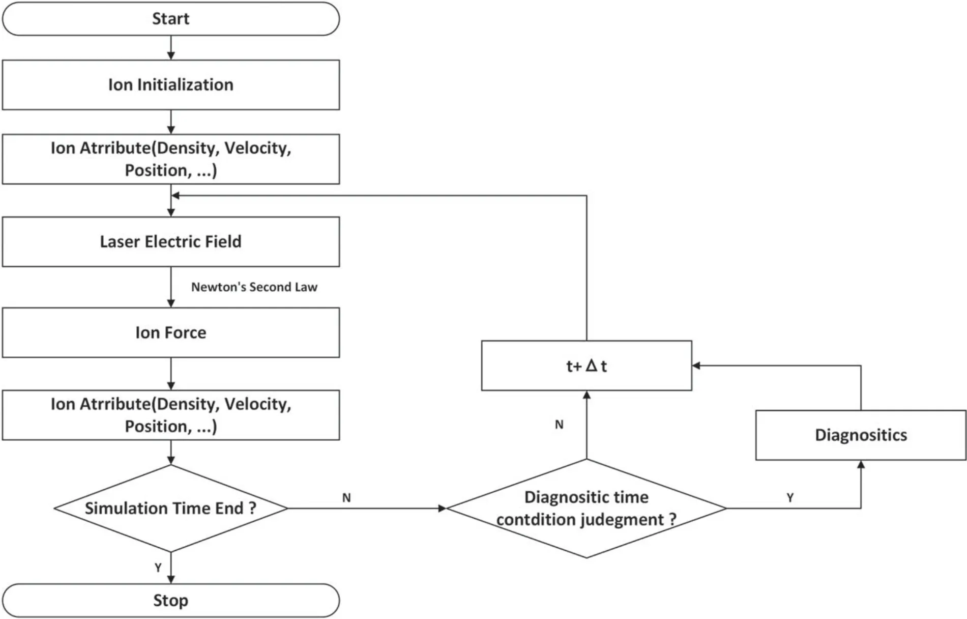
The code flow chart (figure 1) demonstrates how CBETor works.In one cycle,given the ion density,the evolution of the laser electric field can be calculated by equation (1) [24].Using the ion density and laser electric field,one can obtain the total force acting on the ions according to equation (4).The total force pushes ions,and their new positions and velocities can be obtained by advancing equation(5).Finally,the statistical data of ions with new positions give a new ion density.In order to improve computation efficiency,two different time and space scales are used to push the laser and the ions,respectively.When solving the laser wave equation,a set of finer time and space grids is needed.In order to maintain numerical stability,the laser wavelength must be resolved,and the time step must obey the Courant condition[26].When solving the ion motion equation,a set of coarser time and space grids is used,as long as the size of the space grid is large enough to resolve the wavelength of IAW and the size of the time grid is large enough to resolve the ion response time scale.This will greatly reduce the amount of computation compared with the fully kinetic PIC method.
3.1.Difference scheme of the wave equation
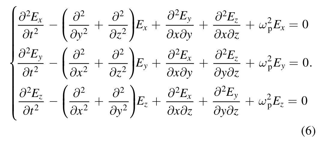
The 3D expansion of equation (1) is as follows:

In 2D geometry (e.g.in the x-y plane),the laser field can be split into two independent polarization states:P-polarization E = (Ex,Ey,0) and S-polarization E = (0,0,Ez).The above equations can be simplified and the finite difference schemes are as follows:

where the superscripts (n+1),n and (n−1) respectively denote the next,current and previous time step,and (i,j)denotes the 2D spatial coordinates (x,y).
3.2.Loading laser on the boundary
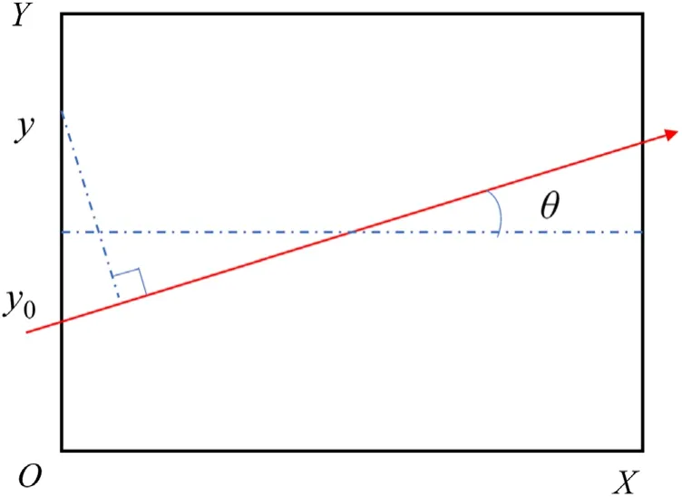
Loading the laser requires updating the laser electric field on the boundary of the simulation box at each time step.If the laser is incident from the left boundary in figure 2,the expression of the laser electric field on the left boundary is,

wherer=y−y0,Here,f and g are the time envelope and space envelope of the incident laser,respectively.A is the amplitude of the laser electric field,θis the incident angle and Φ is the initial phase.
3.3.Laser absorption boundary
The right boundary is set as the Mur absorption boundary[27],which has the advantage of low computational cost.When the laser is incident on the right boundary,it will be absorbed.Figure 3 shows the reflection of the laser on the right boundary at different incident angles,where the background is a vacuum.We define the boundary reflectivity as the ratio of reflected laser intensity to incident laser intensity.By comparing figures 3(b) and (d),it can be seen that the boundary reflectivity rises quickly when the incident angle θ increases.When θ = 5°,the reflectivity is about 4 × 10⁻⁴,while when θ = 35°,the reflectivity increases to about 4 × 10⁻³.In the two simulation examples of this paper,the incident angels are respectively θ = 0° (SBS simulation)and θ = ±5°(CBET simulation),where the Mur absorption boundary works well.

Figure 1.Code flow chart of CBETor.

Figure 2.Schematic diagram of laser loading on the boundary.
3.4.Ion motion
The difference scheme of equations (2)-(4) is as follows:

Ions are usually located inside the grid cell.Therefore,to calculate the force on an ion,it is necessary to interpolate the force on the nearest grid point.After obtaining the ion force,we use the leapfrog scheme to calculate the ion velocity and position as follows:

When the ions move to a new position,we can collect them in each grid cell to obtain a new ion density.In order to reduce the noise of density statistics,a low-pass filter is used to smooth the ion density as follows:

3.5.Ion boundary
The real plasma volume in ICF is in the order of centimeters,so it is very difficult to carry out full-scale numerical simulation.The area we simulate is always much smaller than the volume of the real system.Choosing an appropriate boundary for the simulation box is very important.The commonly used ion boundary types in PIC codes (such as EPOCH) are ‘open’,‘reflective’ and ‘hot’.These boundaries do not work well when a large number of highenergy non-thermal ions leave the simulation box.The ‘open’boundary leads to the loss of a large number of ions from the box,the ‘reflection’ boundary introduces additional high-energy ions,and the‘hot’boundary leads to the accumulation of a large number of hot ions at the simulation boundary.
Here,we propose a new ion boundary to overcome the above defects.We named it ‘ion source boundary’.This boundary introduces an ion source surrounding the simulation domain,as shown in figure 4.The density and temperature of the ion source are the same as those of the box boundary plasma.The ions in the ion source move freely.When they enter the simulation domain,we attach them to the linked list of ions in the domain.When domain ions leave the simulation box,we delete them from the linked list of domain ions.
3.6.Parallel method
According to the number of computer processes,we divide the simulation domain into several sub-domains,and each process is responsible for one sub-domain.Figure 5 shows an example of simulation domain division,in which the simulation domain is divided into npx × npy = 4 × 3 sub-domains,where npx and npy are the maximum number of sub-domains along the x-and y-axis,respectively.Each sub-domain is numbered with an message passing interface(MPI)process number(ID),as shown in figure 5.If the ID of a sub-domain is known,the coordinates(ppi,ppj) can be obtained,where ppi = mod (ID/npx) and ppj = floor (ID/npy).This coordinate can be used for communication between sub-domains.Each sub-domain is surrounded by several guard grids,as shown in figure 6(the red grids).The guard grids are used to exchange the laser electric field,ion density and force at the boundary of adjacent sub-domains.

Figure 3.Reflection of the laser on the right boundary: (a) θ = 5°,t = 20T0;(b) θ = 5°,t = 180T0;(c) θ = 35°,t = 20T0;(d) θ = 35°,t = 180T0.Value in the figure has been normalized with the peak intensity of the incident laser.

Figure 4.Schematic diagram of ‘ion source boundary’.

Figure 5.Arrangement of MPI process numbers in the simulation domain,e.g.the case of npx × npy = 4 × 3.

Figure 6.Parallel sub-region and its guard grids.

Figure 7.Dispersion relationship of the electromagnetic wave in plasma obtained by the Fourier transform of Ez simulated by(a)EPOCH and(b) CBETor.
4.Numerical simulations
In order to verify the correctness of CBETor,we compare the simulation results of CBETor and EPOCH for two specific examples.
4.1.Simulations of SBS in the linear stage
First,we simulate the occurrence of SBS during the propagation of a laser beam in plasma.An S-polarized,Gaussian laser pulse is normally incident on the left boundary.The laser intensity is 3 × 10¹⁶W cm−2,and the waist is 2.58T,where T is the period of the laser.The simulation box is[400λ,200λ],where λ is the laser wavelength.A homogeneous hydrogen plasma with density 0.2nc(ncis the critical plasma density)is in the central region of the simulation box.The length of the plasma is 360λ.The electron and proton temperatures are 2500 and 833 eV,respectively.
According to the linear theory of SBS in homogeneous plasmas [28],the angular frequency and wave number of the incident light(ω0,k0),the backscattered light(ω1,k1)and the ion acoustic wave (ωIAW,kIAW) satisfy the following resonance conditions:ω0=ω1+ωIAW,k0=k1+kIAW.Substituting the initial plasma parameters into a theoretical formula,it is easy to obtain that k0= 0.8944ω0/c,ω1= 0.9953ω0and k1= −0.8898ω0/c,where the minus signal of k1means that it is a backscattered wave.The simulation results of the CBETor and EPOCH are shown in figure 7,where the electric fieldEzis Fourier transformed both in time and space to obtain the dispersion relationship of the electromagnetic wave in plasma.Both the SBS and stimulated Raman scattering signals appear in the simulation results of EPOCH,while there is only SBS signal in that of the CBETor code because the kinetic behavior of electrons is ignored.In the two subgraphs of figure 7,it is shown that the positions of the SBS signals simulated by EPOCH and CBETor are(−0.8896ω0/c,0.9958ω0) and (−0.8895ω0/c,0.9955ω0),respectively.The results agree well and are very close to the theoretical value(−0.8898ω0/c,0.9953ω0).This shows that CBETor can reliably simulate the physical phenomena related to ion response.
4.2.Simulation of CBET
Second,we simulate the CBET effect of two laser beams crossing in a plasma.In this test case,our simulation parameters are consistent with those in [29].Two S-polarized lasers with an angle of 10°cross in a homogeneous hydrogen plasma.There is a small frequency difference between the two lasers: the wavelength is 1 μm for the pump beam and 1.00026 μm for the seed beam.The two lasers have identical temporal and spatial envelope.The laser intensity increases linearly from 0 to 1015W cm−2within 0.53 ps,and then remains constant.The spatial envelope of the laser satisfies the Gaussian functionE⊥=E0exp (−(rcosθ)2/w02)with w0= 28.8 μm in the transverse direction.The plasma density is 0.01nc,and the electron and proton temperatures are 1 keV and 333 eV,respectively.
Figure 8 shows the spatial distributions of laser intensity and ion density at t = 100 ps simulated by two codes.The ion density distributions show the modulation stripes produced by the crossing laser beams,which act as a moving grating.When laser beams interact with the moving grating,SBS-like scattering transfers the laser energy from the pump beam to the seed laser,as shown in figures 8(a)and(c).The simulation results given by EPOCH and CBETor agree well,and are coincident with the results of [29].However,CBETor has a much higher computational efficiency compared with EPOCH.When the testing case is completed,EPOCH uses 1600 computing processes to run for 78 h,while CBETor uses 224 processes to run for only 2.5 h.CBETor improves the computational efficiency by two orders of magnitude.

Figure 8.Spatial distributions of laser intensity((a),(c))and ion density((b),(d))at t = 100 ps.(a)and(b)are results of EPOCH;(c)and(d)are results of CBETor.

Figure 9.Time evolution of CBET gain simulated by CBETor and EPOCH.

Figure 10.Ion phase-space (y,py) distribution at different time simulated by CBETor.Laser intensity is I = 1015 W cm−2.
The evolution of CBET gain with time is shown in figure 9.At each moment,we integrate in the region where x∈[0.8 mm,1.0 mm]to respectively obtain the energy of seed beam and pump beam.The beam energy gain is defined as the ratio of beam energy to the averaged energy.In figure 9,the solid line denotes the energy gain of the seed beam (red) or pump beam(blue)simulated by CBETor,while the solid line with dots denotes the counterpart simulated by EPOCH.Irrespective of whether CBETor or EPOCH is used for simulation,it can be observed that there is a bump structure on the energy gain curve.The seed beam gain increases rapidly to a peak value at about 16 ps,and then decreases rapidly to the bottom value at about 55 ps.After that,the gain increases to saturation.Although the simulation results of CBETor and EPOCH are basically consistent,there are obvious differences.In the EPOCH simulation,the seed beam gain falls more steeply after 16 ps,and saturates at a lower level.
In order to study the physical origin of the bump structure and learn what is behind the difference in simulation results by CBETor and EPOCH,a set of simulations is added where the incident laser peak intensity is decreased to I′ = I/10 = 1014W cm−2,which is called the low-intensity case.The dash line denotes the energy gain of the seed beam(red) or pump beam (blue) simulated by CBETor in the lowintensity case,while the dots denote the counterpart simulated by EPOCH.In this low-intensity case,we find that the simulation results of CBETor and EPOCH are almost identical,and no bump structures are observed.This indicates that the bump structure is a nonlinear phenomenon,which occurs when the laser intensity is high.
In the high-intensity case (I = 1015W cm−2),the ion phase-space (y,py) distribution simulated by CBETor is shown in figure 10,which agrees well with the simulation result by EPOCH shown in our previous work [30].At t = 16 ps,some ions gain positive momentum in the y direction because they are accelerated by the ponderomotive force due to the interference of the crossing beams.The energetic ions can be captured by IAW,as shown in figure 10(b).The normal mode frequency of IAW is nonlinearly shifted by the ion trapping effect,resulting in a decrease in the transferred energy [31].It is shown in figures 10(c) and (d) that some captured ions effectively escape the wave’s potential due to Landau damping,so the energy gain curve rises again after t = 55 ps and gradually flattens out after t = 82 ps.In the low-intensity case(I′ = I/10),no ion trapping effect is observed,so the energy gain curve only rises slowly and tends to be stable.
It can be seen that the bump structure in figure 9 originates from the wave-particle interaction.The difference in simulation results by CBETor and EPOCH in the highintensity case can be attributed to the kinetic behavior of electrons.It is shown that IAWs are affected by the electron kinetic behavior,and the effect is very important whenZTeTi≫10[32].In the high-intensity case,the heating of electrons can be simulated by EPOCH,but the effect is absent in CBETor.In the low-intensity case,the electron heating is not strong,so the simulation results of CBETor and EPOCH agree well.
5.Summary
In this paper,a hybrid-PIC code CBETor is introduced.The physical model,numerical algorithm and implementation are described in detail.In CBETor,the electrons are regarded as fluid,while the ions are treated as particles to retain the kinetic effect.By comparison with the fully kinetic PIC simulations by EPOCH,it is shown that CBETor can simulate the evolution of SBS and CBET with high precision at a much lower computational cost.Currently,ion-ion collisions are not taken into consideration in CBETor,so the effect of collisions on the ion distribution function[20]over long time scales cannot be simulated.It should be pointed out that the scope of application of CBETor is limited.It has medium laser intensity so that the electron heating is not very strong,the plasma density is underdense so that the ion collision effect is not significant,and the incident angle is small so that the absorption boundary works well.Under appropriate physical conditions,CBETor can simulate the kinetic characteristics of the physical process dominated by ion motion with high computational efficiency.
Acknowledgments
This research was supported by National Natural Science Foundation of China (Nos.11774430,11875091,12075157 and 11975062).
ORCID iDs
杂志排行
Plasma Science and Technology的其它文章
- Cross-focusing of two chirped Gaussian laser beams and THz wave generation in plasmas of multi-ion species under a weakly relativistic and ponderomotive regime
- Simulations of energetic alpha particle loss in the presence of toroidal field ripple in the CFETR tokamak
- Impact of core electron temperature on current profile broadening with radiofrequency wave heating and current drive in EAST
- Study on divertor heat flux under n=3 and n=4 resonant magnetic perturbations using infrared thermography diagnostic in EAST
- Ionization process and distinctive characteristic of atmospheric pressure cold plasma jet driven resonantly by microwave pulses
- Experimental and simulated investigation of microdischarge characteristics in a pin-topin dielectric barrier discharge(DBD)reactor
