Method of the left-turning bus priority at intersections based on a variable lane
2022-07-13ChenYonghengLiWanningWuChangjianLiHaonan
Chen Yongheng Li Wanning Wu Changjian Li Haonan
(College of Traffic and Transportation, Jilin University, Changchun 130022, China)
Abstract:To reduce the delay of left-turning buses and improve the traffic efficiency at signalized intersections, a novel variable bus approach lane(VBAL)control method based on bus pre-signals is proposed.This method combines the variable lane with the bus priority pre-signal, and realizes the left-turning bus priority without causing great impact on other vehicles.To validate the effectiveness of the method, the VBAL scheme was compared with the single left-turn lane scheme(SLTL)and the double left-turn lane scheme(DLTL).On this basis, the delay change calculation model of left-turning buses and through vehicles were established by the cumulative curve graphic method.The influence of vehicle proportion and green split on the model was studied through sensitivity analysis.The results show that VBAL can reduce the delay of left-turning bus and the increase of through vehicle delay to the greatest extent.Finally, the scheme was applied to a real-world intersection, and the results demonstrate the effectiveness and advantage of the VBAL scheme.
Key words:traffic engineering; bus priority; dynamic lane; pre-signal; cumulative curve
Bus signal priority is of great significance to improving bus operating efficiency.Current priority methods seldom consider left turns; however, some problems cannot be ignored for left-turning buses.When a bus stop is located upstream of an intersection, left-turning buses stopping at the station always experience difficulties in maneuvering to inner left-turn lanes.More specifically, an upstream bus stop is located in a curb lane, and buses have to merge across multiple lanes to reach a left-turn bay.To solve the merging problem, approaches can be considered, including constructing double left-turn lanes(DLTLs)at intersections.However, left-turning buses still suffer from the difficulty of merging into queuing left-turning cars, which often queue upstream of bus stops during peak hours.To solve this problem, setting up a dedicated bus lane(DBL)for left-turning buses can be considered.In addition, pre-signals can be applied to provide priorities for left-turning buses.
In the present study, transit signal priority(TSP), DBLs, and intermittent bus lanes(IBLs)have been used to provide bus priorities.By adjusting traffic signal plans based on bus arrivals, the delay of buses can be reduced[1].A DBL can be combined with TSP to improve its advantage, but it is only suitable for light volumes of cars because it removes one lane from conventional lanes[2].Viegas et al.[3]proposed the use of IBLs, where cars are forbidden to use lanes downstream of advancing buses.However, when there is no bus arriving, cars using such lanes could increase discharges from the arterial[4].
In addition, as a common bus priority method, pre-signals have been widely used in urban road intersections.There are two types of pre-signals: whole pre-signal and local pre-signal.In a whole pre-signal, all lanes should be set with a pre-signal.To accurately evaluate a whole pre-signal, He et al.[5]proved that bus priorities with pre-signals could improve the intersection capacity.Follow-up studies gradually focused on the control model optimization of pre-signals and the solution method of related parameters[6-10].To meet the diverse traffic demand of intersections, local pre-signals were proposed.In local pre-signals, only one or several lanes are set with pre-signals.In this case, bus priorities can be provided without affecting other movements.A local pre-signal is usually combined with a complex, unconventional design, such as a contraflow left-turn design[11].
However, the two methods will increase the delay of non-priority vehicles and cause waste of space resources at intersections when the proportion of left-turning buses is low.Hence, in this study, a left-turning bus lane is set upstream of the adjacent lane of a left-turn lane, which is controlled by a pre-signal.The downstream of the pre-signal is a variable lane in which buses and non-priority vehicles are allowed to travel simultaneously.The aforementioned approach can save the lane-changing time for left-turning buses.Moreover, the non-priority through vehicles can enter the variable lane, which would minimize the increased delay of non-priority vehicles.
1 Design Concept of VBAL
The intersection implementing the variable bus approach lane(VBAL)scheme shall meet the following conditions:
1)There shall be at least three or more lanes at the approach.
2)A sufficient distance shall be reserved between the stop line and the upstream bus stop.
3)The saturation of the intersection should be less than 0.9.
4)There should be a relatively stable number of left-turning buses arriving in each cycle.
1.1 Geometric and phase design
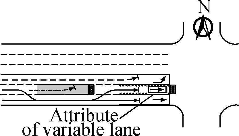
The geometric design of the VBAL is shown in Fig.1(a), while a reference design for a pre-signal and placard is shown in Fig.1(b).The variable lane is located in the zigzag marking section, which can be used by through vehicles and left-turning buses at different times.The shadow area upstream is a dedicated waiting area for left-turning buses.The section between the two areas is a lane-changing section for non-priority vehicles.

(a)
Three common phases,namely, four-step phase, single-approach-released-in-turn(SARIT)phase, and overlapping phase, will be discussed in this section.For the convenience of description, traffic methods are explained as follows in the case of the main signal being red, through green, left-turn green, and through-left green.
1)Queue distribution.Left-turning cars wait in the left-turn lane.Left-turning buses queue on the bus lane, and through vehicles wait on the variable or through lanes(see Fig.2(a)).
2)The main signal is through green.In stage 1, the through vehicles pass the intersection from a variable lane or through lanes.Left-turning cars and buses queue up on the left-turn lane and waiting area, respectively(see Fig.2(b)).In stage 2, waiting left-turning buses are allowed to enter the variable lane ahead of time(see Fig.2(c)).
3)The main signal is left-turn green.In stage 1, left-turning buses and cars would be released(see Fig.2(d)).In stage 2, after all the waiting left-turning buses are released, left-turning cars are allowed to enter the inner left-turn lane or variable area(see Fig.2(e)).
4)The main signal is through-left green.In stage 1, left-turning buses pass the intersection through a variable area(see Fig.2(f)).In stage 2, through and left-turning vehicles could be allowed to use the variable area to pass the intersection(see Fig.2(g)).
(a)
As discussed above, the traffic methods under the three phases can be obtained by recombining the above situations.In the four-step phase, the release process of the vehicle is(a)→(b)→(c)→(d)→(e).In the case of SARIT, the process is(a)→(f)→(g).In the overlapping phase, the process is(a)→(b)→(f)→(g)(see Tab.1).In addition, the pre-signal cannot turn green in advance in the SARIT phase because through vehicles would queue on the variable lane, which leads to the loss of priority for left-turning buses.Therefore, whether the SARIT phase can be applied to provide priorities for left-turning buses has great uncertainties.

Tab.1 Steps for vehicle release in the VBAL scheme under different phases
1.2 Calculation model of control parameters
The green time of a pre-signal consists of the green time starting in advanceg1and green durationg3.Left-turning buses can reach the stop line of the main signal withing1, and the stranding phenomenon is also avoided.
(1)
g3=g2-g1
(2)
wherel3andl2denote the length of the variable lane and lane changing section, m, respectively;vis the average speed of buses, m/s;Lis the lost time of vehicle starting, s; andg2is the left-turn green time of the main signal, s.
The geometric parameters of the VBAL depend onl1,l2, andl3, wherel3is equal to the approach lanes, andl1should meet the maximum queuing distance required for left-turning buses.Suppose that the number of left-turning buses arriving and departing in each signal period isaandb, respectively.Then, the probability ofαleft-turning buses queuing in the waiting area,Pα, can be given by[12]
(3)
The maximum number of queuing busesMcan be obtained by
(4)
l1andl2are given by[12]
l1=Mlb+(M-1)l
(5)
(6)
wherelbdenotes the average length of buses, m;lrepresents the safe stopping distance of buses, m;vis the speed of cars, m/s; andθdis the desired heading angle of cars.
2 Person-Based Delay Model
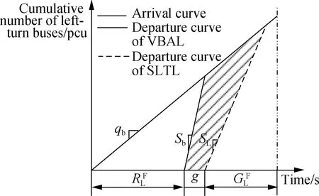
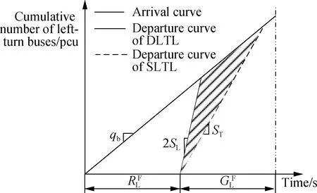
2.1 Four-phase

(a)
(7)
(8)
(9)


(10)
(11)


(12)

(a)
(13)
(14)
(15)


(16)
The average variation of delays can be calculated as
(17)
(18)
wherepb,pT, andpLare the proportions of left-turning buses, through vehicles, and left-turning cars arriving at the intersection in a cycle, respectively;obandocare the average number of passengers carried by buses and cars, respectively.
2.2 Overlapping phase

(19)
(20)


(a)
(21)
(22)

(23)
(24)

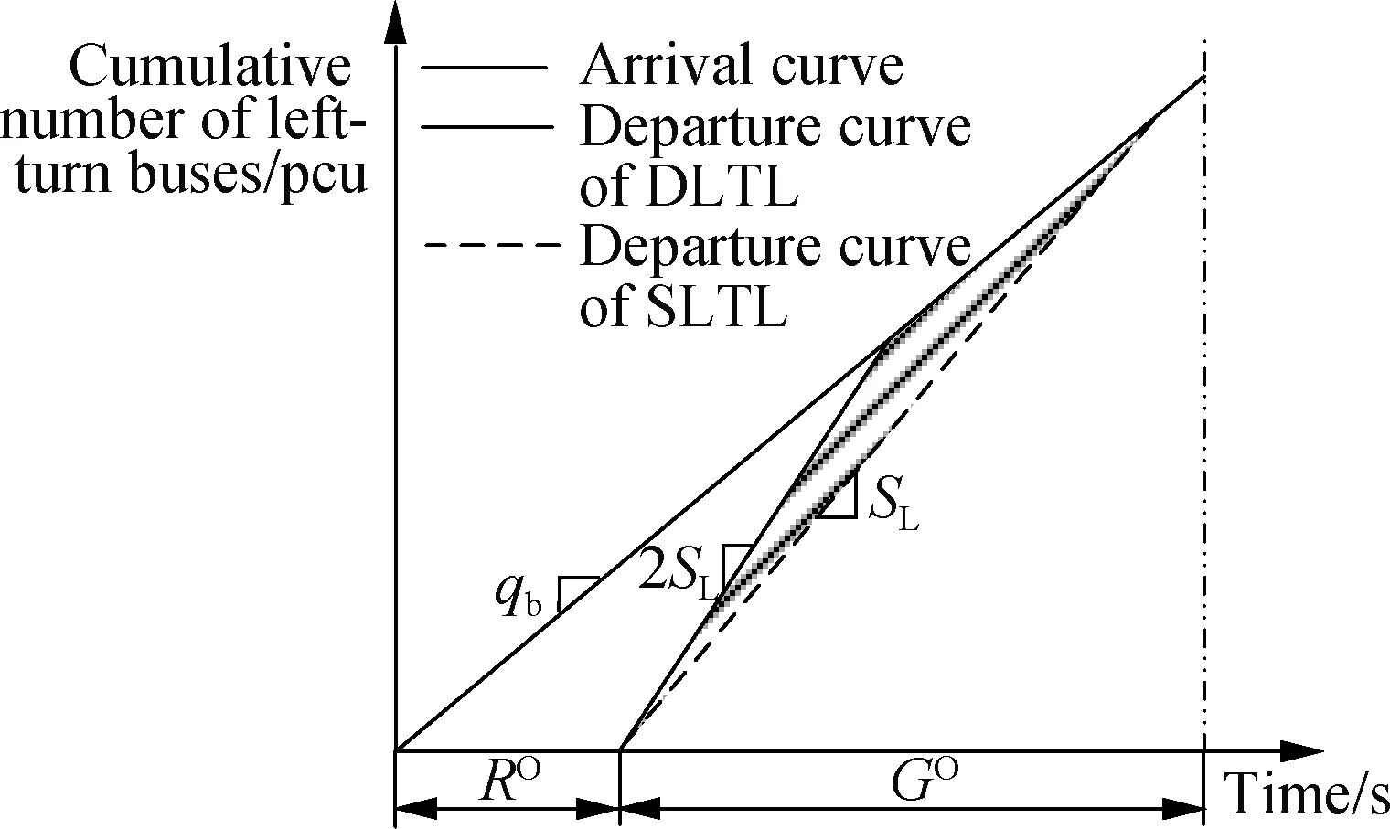
(a)
(25)


(26)
The average delay variation of the schemes can be calculated as follows:
(27)
(28)
3 Sensitivity Analysis
A sensitivity analysis was conducted using MATLAB(2017a)to analyze the impacts of the vehicle arrival rate, green split of the main signal, and proportion of vehicle types.Suppose the cycle length was 180 s.The saturation flow rates of left-turn lanes and through lanes were 0.3 and 0.6 veh/h, respectively.The saturation flow rate of left-turning bus lanes was 0.5 veh/h.The average passenger occupancy of cars and buses was 5 and 40 per/veh, respectively.The advance time of pre-signal was 9 s.
As shown in Fig.7(a), the delay reduction of left-turning buses in the VBAL scheme is larger than that in the DLTL scheme.Moreover, the VBAL scheme with an overlapping phase has the largest reduction of left-turning bus delay.The greater the arrival rate of left-turning buses, the greater the delay reduction.As shown in Fig.7(b), with the increase in green split, the reduction in the left-turning-bus delay gradually decreases.In the two phases, the reduction in the left-turning-bus delay in the VBAL is greater than that in the DLTL.

(a)
As shown in Fig.8(a), the delay increase of the VBAL scheme is the lowest under the overlapping phase, and the curve of the increase in delay tends to be flat with the increase in the arrival rate of through vehicles.While the arrival rate of through vehicles reaches approximately 3 000 veh/h, the increase in delay would significantly increase.As shown in Fig.8(b), the increase in delay under the VBAL scheme is lower than that in the DLTL scheme.Clearly, the curve of the VBAL scheme gently changes around 0, which proves the implementation advantage of the VBAL scheme again.

(a)
As shown in Fig.9(a), the greater the proportion of left-turning buses, the greater the reduction of delay on the approach road.The DLTL scheme under the overlapping phase is not suitable for intersections because although its delay shows a downward trend, the variation of delay is always positive.In the other three schemes, the VBAL scheme with an overlapping phase has the largest delay reduction.As shown in Fig.9(b), it has the opposite tendency as compared to that in Fig.9(a).The VBAL scheme with an overlapping phase has the largest delay reduction.

(a)
4 Case Study
The effectiveness of the three schemes was evaluated at an intersection, i.e., the Furong-Xinyao Road located in Changsha.The traffic volume during the peak period is shown in Tab.2.The overlapping phase was adopted inthe north approach.Hence, the north approach was selected to evaluate the three schemes.Meanwhile, the signal timing of the VBAL scheme was obtained based on Eqs.(1)and(2), as shown in Fig.10.According to Eqs.(3)to(6),l3andl2are 32 and 14 m, respectively.
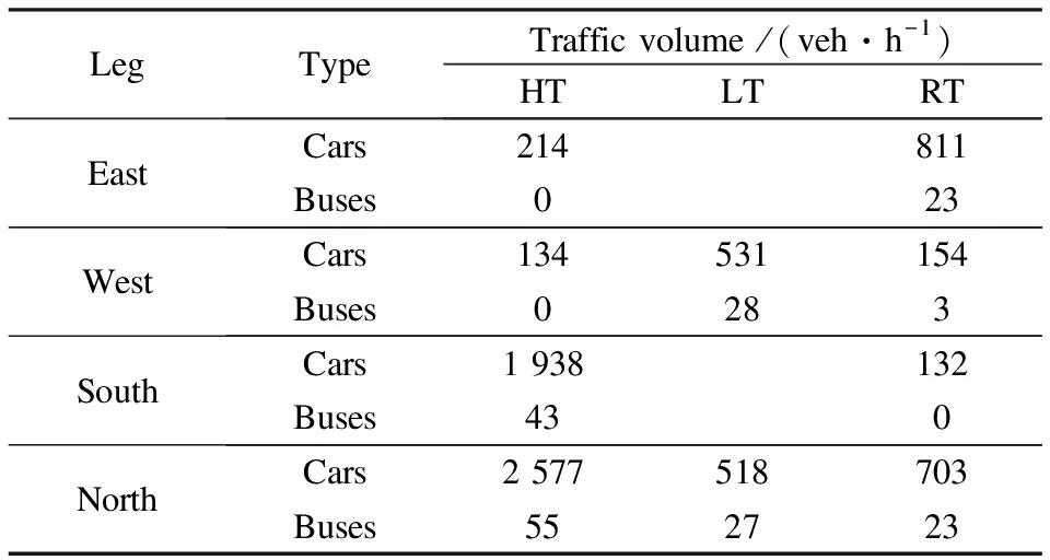
Tab.2 Traffic flow at the intersection
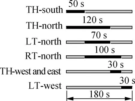
(a)
We inputted the above data into the delay model, and the results are shown in Tab.3.In the VBAL scheme, the delay of left-turning buses decreased by 5.56 s, whereas in the DLTL scheme, it only decreased by 0.05 s.For through vehicles, the delay of the DLTL and VBAL schemes increased by 8.2 and 0.85 s, respectively.Hence, the VBAL scheme can effectively reduce the delay of left-turning buses and minimize the increase in through-vehicle delay.

Tab.3 Comparison of the average variations
To further verify the applicability of the method, VISSIM11.0 was used to simulate the three schemes.As shown in Tab.4, the delay reduction of left-turning buses is lower under the DLTL scheme than that under the VBAL scheme, whereas the delay of through vehicles was significantly increased.The queue length of the left-turn lane in the VBAL scheme was less than that of the DLTL scheme, but the queue length of through vehicles was slightly increased.Hence, the VBAL scheme is more suitable than the DLTL scheme.

Tab.4 Simulation results of each scheme
5 Conclusions
1)This paper presents a novel left-turning bus priority method called VBAL.Under this method, left-turning buses are provided with priorities by combining a variable lane and local pre-signal.Accordingly, the increase in through-vehicle delay can be minimized.
2)As an evaluation method, a cumulative curve was used to establish a delay calculation model.On this basis, the VBAL, DLTL, and SLTL schemes were compared through sensitivity analyses and case studies, and the results validated the feasibility of the VBAL scheme.
3)In the real world, variable areas are crowded with other vehicles, and a through vehicle getting stuck in a VBAL would occur.These problems need the implementation of electronic signs, movable guardrails, and other traffic facilities.
杂志排行
Journal of Southeast University(English Edition)的其它文章
- Multi-head attention-based long short-term memory model for speech emotion recognition
- Graph-enhanced neural interactive collaborative filtering
- Path prediction of flexible needles based on Fokker-Planck equation and disjunctive Kriging model
- Mapping relationship analysis of welding assembly properties for thin-walled parts with finite element and machine learning algorithm
- Dependency-based importance measures of components in mechatronic systems with complex network theory
- Feasibility analysis of using biomass gas or hydrogen in the tobacco curing system
