Seismic performance of a reinforced concrete building retrofitted with self-centering shape memory alloy braces
2022-07-12MassimilianoFerraioliAntonioConcilioandCarmineMolitierno
Massimiliano Ferraioli, Antonio Concilio and Carmine Molitierno
1.Department of Engineering, University of Campania “Luigi Vanvitelli”, via Roma 29, 81031 Aversa (CE), Italy
2.Adaptive Structures Div., the Italian Aerospace Research Centre (CIRA), via Maiorise, 81043 Capua (CE), Italy
3.Department of Structures for Engineering and Architecture, University of Naples “Federico II”, via Claudio 21, 80125, Napoli, Italy
Abstract: Self-centering earthquake-resistant structures have received increased attention due to their ability to reduce post-earthquake residual deformations and, thus, repair time and cost.This stimulated the development of recentering shape memory alloy (SMA) dampers that use superelastic nitinol wires to dissipate energy and self-center the structure.However,there are still a few case studies applications on full-scale RC buildings in the literature.Moreover, general guidelines or even simplified approaches for the practical design of SMA damped braces are still lacking.This paper focuses on evaluating the effect of using self-centering shape memory alloy dampers for buckling-restrained braces applied for the seismic retrofit of a complex RC building structure.A design method originally proposed for elastoplastic dampers was implemented to size the SMA dampers to be placed on selected spans and stories of a building.The effectiveness of the design procedure was demonstrated by nonlinear time-history analyses under different sets of earthquake strong ground motions.The analysis results show that the recentering shape memory alloy bracing system is effective in limiting the maximum transient inter-story drifts and reducing the residual inter-story drifts after strong seismic events, due to its excellent recentering behavior together with its not negligible energy dissipation capacity.
Keywords: RC buildings; seismic retrofit; buckling-restrained braces; shape memory alloys dampers; self-centering
1 Introduction
1.1 Background
The collapse of RC buildings is often the major cause of loss of life and property during earthquake ground motions.Buildings designed for gravity loads only suffer heavy damage and often collapse from the effects of strong earthquakes.On the other hand, seismically designed buildings are expected to possess the necessary properties to withstand the design earthquake excitations corresponding to the life safety (LS) limit state.However, the LS performance is based on significant structural damage to dissipate seismic energy.Thus,large lateral drifts may occur during seismic events,thus leading to extensive damage.Moreover, large residual inter-story drifts may be experienced, thus exceeding the repairable limit of 0.005%.Therefore,protection against economic loss is not guaranteed since residual inter-story drifts make demolishing a damaged structure more favorable than the option of repairing it.Starting from these considerations, a new generation of seismic codes has placed increased emphasis not only on stiffness, strength, and ductility requirements but also on structural resilience, which is the ability to rapidly resume the use of buildings and structures following an earthquake.The main goal of the seismic design codes is being shifted from collapse prevention to repairable damage to minimize the economic impact of earthquake hazards.According to this new design concept, both damaging and residual deformation of a building after an earthquake should be controlled.Thus,new seismic resisting systems are needed to dissipate energy, minimize structural damage, and return the structure to its initial position (self-centering capability),making it repairable after high-intensity earthquakes.The conventional retrofit strategies for RC buildings generally use concrete or steel jacketing for add new structural systems, such as RC shear walls or concentric braces, to absorb most seismic actions.Other retrofit strategies are based on passive control, thus involving the reduction of seismic demand by seismic isolation and supplemental damping (Ferraioli and Mandara,2016, 2017; Zhouet al., 2018; Yanget al., 2020).An alternative approach introduces energy dissipation devices (such as viscous fluid dampers, friction dampers,and steel hysteretic dampers) that are incorporated in steel braces that connect two consecutive stories.This solution overcomes the main limitation of conventional concentric bracing systems (CBSs) that perform poorly due to the buckling of compression braces.Energy dissipation devices are activated before structural elements enter into the plastic or buckling stage.Thus,by restraining the buckling of the bracing members, the buckling restrained braces (BRBs) exhibit high ductility and stable hysteretic energy dissipation capacity in both tension and compression.However, their energy dissipation capacity under strong earthquake ground motions often involves high plastic strains.Therefore,like some other energy dissipation devices, the BRBs undergo excessive deformations and permanent residual drifts and do not recover their original shape after unloading (Zhuet al., 2008; Erochkoet al., 2011; Qiuet al., 2018; Ghowsiet al., 2013, 2015 and 2019).These considerable residual inter-story drifts increase repair time and costs following earthquakes and, in many cases,require building demolition.Moreover, aftershocks or subsequent earthquakes can induce additional permanent residual drifts, thus increasing the cumulative damage and probability of collapse.To reduce residual story drift,Kigginset al.(2006) suggested a dual system design by which the addition of special moment-resisting frames can serve as a restorative force mechanism to partially re-center a building after strong earthquake ground motions.However, the problem of providing selfcentering capability, even under the influence of strong earthquakes, still deserves to be investigated since it remains a significant issue in controlling repair costs and downtime.
1.2 Relevant prior research
Many types of self-centering (SC) systems have emerged as promising passive dampers for seismic applications because of their ability to significantly reduce residual inter-story drifts even after strong ground motions.Replaceable yielding and friction energy dissipation elements have been developed; they easily can be substituted following the occurrence of strong ground motions (Christopouloset al., 2008; Dowdenet al., 2011; Claytonet al., 2012; Eathertonet al., 2014;Chouet al., 2014; Xuet al., 2016).The use of innovative materials may be useful for limiting residual Inter-story drifts.Among them, shape memory alloys (SMAs) are gaining increasing relevance.The alloy of nickel and titanium (NiTi based SMAs) is the most common SMA material used in applications for civil structures.This material has been extensively used for vibration control devices (i.e., base isolation systems, energy-dissipating dampers, bridge restrainers, beam-column connections,concentric braces, reinforcement or prestressing bars) because of its high energy dissipation capacity,excellent corrosion, and fatigue resistance (Concilioet al., 2021).Moreover, NiTi SMAs elastically recover large deformations (up to 8%) and this superelastic behavior allows for developing flag-shape hysteretic loops under cyclic axial loading with negligible residual deformations.This situation makes the structure usable and repairable even after strong ground motions(DesRocheset al., 2004; Zhuet al., 2007; McCormicket al., 2007; Yanget al., 2010).Many studies in the literature have focused on self-centering SMA-based devices of different shapes and operating principles.In particular, the first studies used SMA wires to develop restrainers, braces, and dampers (Dolceet al., 2001;Songet al., 2006; Zhanget al., 2008; Padgettet al., 2010;Fanget al., 2015; Qiu and Zhu, 2017).Subsequently, SC systems based on SMA bars have been developed, since the bars were found to be easier to connect and better meet strength seismic demand when compared to wires(Fukutaet al., 2004; Speicheret al., 2009; Fanget al.,2014; Youssefet al., 2015; Wanget al., 2017).Various forms have been studied, such as helical springs (Fanget al., 2015; Zhuanget al., 2016), wires and bars (Rohlfet al., 2012; DesRocheet al., 2004; Qiuet al., 2020; Soulet al., 2015), special braces for framed structures, and isolation devices for buildings and bridges (Dolceet al.,2000; Dinget al., 2011), tensile tendons that provide the self-centering force (Abolmaaliet al., 2006; Jankeet al.,2005) and are concentrically braced (Qiuet al., 2017;2018).In general, self-centering systems can be grouped into three categories: 1) braced frame systems (Zhuet al., 2007; Christopouloset al., 2008; Yanget al., 2010);2) rocking systems (Perezet al., 2007; Eathertonet al.,2014); and 3) systems with horizontal post-tensioned(PT) steel elements (bars or strands) (Ricleset al., 2001;Christopouloset al., 2002).SMA-based bracing systems seem to be more promising for practical exploitation.Thus, many studies on the subject have been presented in the literature.Auricchioet al.(2006) used large diameter,superelastic Nitinol bars as an innovative bracing system for steel structures.McCormicket al.(2007) developed an extensive analysis of concentrically braced frame systems, implementing either conventional steel braces or superelastic shape memory alloy braces.Speicheret al.(2009) developed and tested a device designed to allow Nitinol forms to be used in compression in bracing systems.Ozbulutet al.(2010) highlighted the advantages of using SMA damping devices for the seismic protection of steel frame structures.Yanget al.(2010) developed a hybrid seismic device composed of a set of re-centering wires fabricated from SMA material, two energy-absorbing struts, and two highstrength steel tubes to guide the movement of a hybrid device.Asgarianet al.(2011) investigated the seismic performance of steel frames equipped with superelastic SMA braces with various bracing configurations.Kariet al.(2011) conducted a numerical study to investigate the benefit of using a combination of buckling restrained braces and SMA braces for both new design and a seismic retrofit of existing structures.Milleret al.(2012)presented the development and experimental validationof a self-centering (SC), buckling-restrained brace(BRB), which uses pre-tensioned superelastic nickeltitanium (NiTi) shape memory alloy (SMA) rods to provide self-centering and additional energy dissipation.Jalaeefaret al.(2012) proposed an innovative SMA-based device using NiTi SMA bars tested under cyclic tension-compression loading.Qianet al.(2013)proposed a recentering shape memory alloy damper(RSMAD) that uses superelastic nitinol wires as energy dissipation components.Moradiet al.(2014) conducted an extensive numerical study of the seismic performance of braced frames with either BRBs or superelastic SMA braces.Huet al.(2014) proposed a new innovative system that achieves superior recentering behavior by using superelastic SMA into BRB.Eathertonet al.(2014) developed and experimentally validated a selfcentering buckling-restrained brace (SC-BRB) that uses concentric tubes held flush with pre-tensioned shape memory alloy rods.Chouet al.(2014) developed a new steel dual-core, self-centering brace (DC-SCB) to effect a flag-shaped re-centering hysteretic response under cyclic loads.Yeet al.(2020) proposed an innovative re-centering energy dissipation brace (named RCED)by which re-centering is provided through the use of two groups of steel cables without pretension, thus overcoming the problem of pretension loss.Zhanget al.(2020) evaluated the structural behavior of steel frames with RCED braces by means of experimental tests on three full-scaled structures with various bolt pretensions and cable diameters.Donget al.(2019) first experimentally investigated the mechanical properties of SMA cables and studied the seismic response of steel frame structures equipped with self-centering energy dissipation braces based on SMA cables.Fanget al.(2020) studied the seismic performance of steel frame buildings with SMA-based, self-centering bracing systems using a probabilistic method.Liuet al.(2018) theoretically and numerically investigated the effect of trilinear hysteresis behavior on the seismic response of self-centering, buckling-restrained, braced steel frames.Ghowsiet al.(2020c) developed and tested hybrid buckling-restrained braces with Fe-based SMA core elements.Ghowsiet al.(2020a) focused on finding the optimal design parameters of SMA bars to maximize hysteretic energy dissipation and re-centering behavior of SC-BRBs.Qiuet al.(2020) numerically and experimentally investigated a new SMA-steel damper,which combines steel dampers based on bending steel plates and SMA bars.Ghowsiet al.(2020b) studied the seismic performance of low- to high-rise steel buckling restrained braced frames (BRBFs) equipped with SCBRBs under near-field ground motions.
1.3 Research objective
Although many studies have been presented in the literature on SMA bracing systems, most of them are devoted to experimental and numerical investigations on small-scale SMA devices or brace components and focus on the hysteretic behavior of SMA-based devices under cyclic loading.Many studies are dedicated to SMA-brace devices applied to steel moment frames containing concentric bracing.Only a few studies focus their attention on the application of SMA-brace devices to RC buildings, particularly for the seismic retrofit of existing structures.Moreover, these studies generally present numerical analyses or experiments on small scale brace-components to test their applicability to the seismic retrofit of steel and reinforced concrete frames, while applications to RC buildings are still lacking.Thus, more insights are necessary to understand the complex nonlinear response of full-scale building structures retrofitted with SMA-based braces.Moreover,little has been done in developing effective modeling techniques and design procedures for seismic loadings.Thus, further efforts seem necessary to implement general guidelines or simplified approaches for the practical design of these systems.The innovation of this article is to investigate the potentiality of the SMA-based system when implemented on an actual building.To this aim, effective modeling techniques and design procedures were developed and applied to size the buckling-restrained SMA braces.Their effectiveness as a re-centering and damping structural element was finally evaluated through nonlinear static and dynamic analyses based on suites of earthquake ground motion records that represented different seismic hazard levels.
2 Self-Centering shape memory alloy braces
2.1 Mechanical properties of SMAs
Shape memory alloys display unique properties that are not present in all traditional civil engineering materials.Their thermomechanical behavior depends not only on stress and strain but also on temperature(Fig.1).Basically, it may exist in two different states,called phases, at the same temperature as a function of the imposed stress field, or at the same level of stress as different temperatures are imposed.For materials whose austenite transition is higher than the environmental (or operational) temperature (austenite start,As), a residual strain remains after unload.This residual strain is completely recovered if the SMA is heated beyond the austenite finish temperature (Af).This phenomenon is commonly known as the Shape Memory Effect (SME).Coherently, for materials whose austenite complete transition is lower than the environmental (or operational)temperature (T≥Af), the stress-strain diagram shows different behavior, namely,: 1) the elastic response of austenite at low strains; 2) a stress plateau due to the transformation from austenite to martensite; 3) an elastic response during the martensite phase for large strains;4) the elastic recovery of strain upon stress removal; 5)the recovery of strain at almost constant stress due to the transformation from martensite to austenite; and 6) theelastic recovery of strain in the austenite phase after the above conversion is completed.The subsequent nonlinear stress-strain relationship leads to a flag-shaped hysteresis loop that shows the property of SMA to dissipate a significant amount of energy and recover its original shape after experiencing large strains.This property is known as super-elasticity (SE) or pseudo-elasticity(PE).Finally, if the working temperature exceeds the maximum temperatureMdat which martensite occurs(T≥Md), the SMA behaves like an elastic-plastic material.The super-elastic hysteretic properties are strictly related to the elastic modulus of each phase (EAandEM), the characteristic transition stresses (namely,σMsandσMfin the phase transformation from austenite to martensite;σAsandσAfin the phase transformation from martensite to austenite), and the corresponding strains.The constitutive diagram may be schematically summarized by using straight lines that define the complete domain boundary (Fig.2).These lines may have different slopes as a consequence of stiffness and transition properties modulation, depending, in turn, on SMA composition.These parameters affect the hysteresis area and, thus, the energy dissipation capacity; therefore, they may be key design points for the realization of suitable SMA-based dampers.Thus, the selection of the SMA material should be done to provide a large hysteresis area exhibiting the max difference:
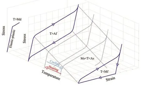
Fig.1 3D stress-strain-temperature diagram of NiTi-based SMA

Three parametersα,β, andγ(Fig.2) are generally used to determine the postyield stiffness ratio (α), the hysteresis width (β), and the ratio (γ) of martensite stiffness to austenite stiffness for describing the hardening behavior.In general, the hardening behavior may induce significant residual deformation.However, for FeNiCuAlTaB- and CuAlBe-based SMAs the ductilityμ(that is defined as the ratio ofεMftoεMs) is very high and, thus, only their superelastic strain is exploited.The NiTi-based SMA (which is the most widely used SMA in seismic applications) has the lowest ductility compared to other shape memory alloys (i.e., a superelastic strain up to 6%-8%) followed by hardening behavior.The martensitic hardening characteristics of SMAs under large amplitudes may critically affect their behavioral performance for structural safety protection under strong earthquake ground motions.However, the strain hardening behavior caused by the martensite phase can be avoided through proper treatment (Dolceet al., 2000;Dolce and Cardone, 2001).Liet al.(2021), reports that nano-grains and dislocation networks can lead to a homogeneous distribution of NiTi grains, reinforcing the original matrix and resisting the plasticity process during repetitive martensitic transformation, thereby finally improving stability during cyclic superelastic loading.In general, it can be stated that (Kanget al., 2020) the increased use of SMA in civil applications is increasingly drawing attention to treatments and technology to improve materials performance.Whenever it may occur, induced strain hardening in a deformed SMA can be eliminated by a specific heating process (Benafanet al., 2015; Hendersonet al., 2011).Since overheating could damage the shape memory alloys material and reduce its expected lifespan, this action should be performed carefully (Janiet al., 2013).Different authors have suggested limiting the temperature excess to 40 or 50°C (Hendersonet al., 2011; Fukutaet al., 2004).As stated above, the strain hardening behavior caused by the martensite phase is not considered in this study.
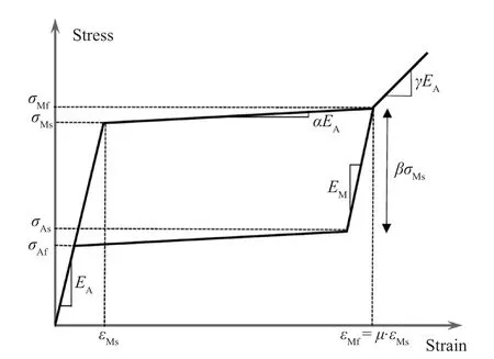
Fig.2 Stress-strain model of NiTi-based SMA
2.2 Modeling and material identification
In the case of SMA braces, the damped brace is divided into two segments to reduce the length of the required SMAs: 1) a super-elastic and re-centering SMA damper, and 2) a brace designed to avoid buckling(Fig.3).This paper applies an innovative re-centering SMA damper (RSMAD) developed and experimentally validated by Qianet al.(2013).This damper uses the recentering and energy dissipating features of superelastic nitinol SMAs.Figure 4 shows the schematic representation of the re-centering SMA damper.The RSMAD is composed of: (a) an outer cylinder, (b) aninner cylinder, (c) a left pull plate, (d) a right pull plate,(e) pre-tensioned shape memory alloy nitinol cables, (f)a retaining plate with fixed bolt, (g) a pre-strain adjusting plate with an adjusting bolt, (h) a push-pull rod, (i) a grip, (j) end caps, and (k) a connecting fitting.The prestrain adjusting plate and the corresponding adjusting bolt are used to adjust the pre-strain of the superelastic cables.The RSMAD damper is connected to the structure by using the push-pull rod and the connecting fitting.When subjected to cyclic loading, the push-pull rod moves in both directions (forward and reversed),and provides damping, thanks to the energy dissipation capacity of the SMA cables.It then returns to its initial position (demonstrating its self-centering capability).The SMA cables are always subjected to axial tension for any phase of applied cyclic loading.In this paper,the computational model of SMA cables was calibrated by comparing the predicted hysteretic response with past test results that are available in the literature.To this end, uniaxial tests carried out by Rizzoniet al.(2015)on commercial super-elastic NiTi wires were used for calibration.The wires have a diameter of 1 mm and a an Ni content of 54.8%.The ranges of transformation temperatures of NiTi-based SMA are plotted in Table 1.The mechanical properties were derived by Rizzoniet al.(2015) through the use of uniaxial tensile tests performed on test specimens having an overall length of 200 mm.Material identification was based on the stress-strain curves obtained at a temperature of 25° for a strain rate of 1 mm/min.Figure 5 shows the corresponding stressstrain curve obtained from the experimental test.In this paper, the hysteresis behavior of SMA under cyclic loadings was modeled using the uniaxial loading model originally proposed by Auricchio and Sacco (1997) and then modified by Fugazza (2003).This model (hereafter referred to as the AF model) is based on the following simplifying hypotheses:
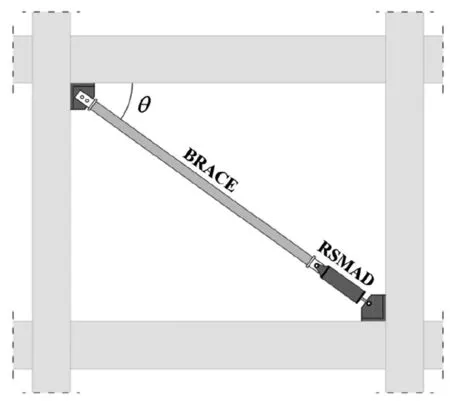
Fig.3 Self-Centering SMA (SC-SMA) brace
· the response is assumed to be symmetric in tension and compression;
· the stress-strain behavior is represented by a series of straight lines;
· strength deterioration due to cyclic loading is neglected; and
· the same stiffness for the fully austenite and fully martensite states is considered (i.e.,EA=EM).
Figure 5 compares the experimental stress-strain curve with the simulations obtained by employing different numerical models: a) Kim and Abeyaratne′s model (1995) (named the KA model); b) Isothermal′s approximation of the KA model; c) Auricchio, Fugazza and Des Roches′ model (2008) (named the AFD model);and d) the AF model implemented in SAP 2000 using the damper friction spring model (named the AF-SAP model).More details about the experimental data and the parameters identification of the KA model, the isothermal KA model, and the AFD model may be found in Rizzoniet al.(2015).For small and moderately large strain rates, all the models show good agreement with the experimental data.At large strain rates, the isothermal approximation of the KA model and the AFD model exhibit smaller stresses near the end of the transformation.
Figure 5 shows that the AF-SAP model may successfully reproduce the hysteretic response of SMA under cyclic loading.However, it is worth highlighting that the AF model used in this paper is valid within certain boundaries.First, it is aimed at representing super-elastic behavior only.In other words, it is assumed that the temperature field is such that the material naturally and entirely transforms into austenite as the load system isremoved.The superelastic behavior is characterized by a flag-shapes constitutive diagram that is representative of load-unload cycles.The hysteretic loops under cyclic excitation allow the dissipation of adequate amounts of energy.The property of fully recovering even large strains(namely, more than 10%) with no residual deformation makes the self-centering, buckling-restrained braces(SC-BRBs) different from conventional BRBs that exhibit nearly ideal bilinear hysteretic loops.Moreover,the AF-SAP model is independent of strain rate and temperature (within the aforementioned boundaries,i.e., the temperature field will never exceed low values to inhibit fully austenite recovery) and, therefore, it cannot capture stress that increases with loading rate and temperature.The same holds true for the case in which the external temperature falls below a certain threshold (a twinned martensite start).Finally, it neglects martensitic hardening behavior.However, for the NiTi-based SMA,the onset of strain hardening behavior starts at around 6%-8% of the true strain and, thus, the SMA damper may be designed to not exceed this limit.In any case, a specific heat treatment may be applied to minimize that particular phenomenon (Benafanet al., 2015; Hendersonet al., 2011).Since NiTi-based SMAs are substantially independent of oscillation frequency in the range of interest for seismic applications, the implemented model can be sufficient for describing the overall behavior of the system, as per the defined operational hypotheses.In the same way, other physical characteristics are nearly insensitive to temperature and are compatible with typical applications of structural engineering.Therefore,despite the aforementioned simplifying hypothesis, the overall schematization may be said to be adequate to simulate system behavior within established conditions,and the results obtained are expected to be reproduced in a complete approach.
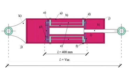
Fig.4 Recentering SMA damper (RSMAD)
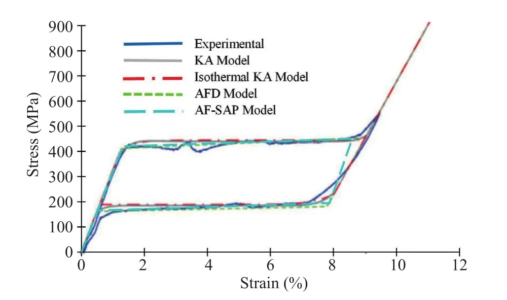
Fig.5 Force-displacement model of SMA wire
3 Building modeling and seismic analysis
The use of hysteretic dampers for the seismic retrofit of existing frame structures is an effective strategy for mitigating earthquake-induced risks.However, its application in current practice is rather limited since simple and efficient design methods are still lacking.Many of the design procedures available in the literature are based on shear beam models and simplified hypotheses.Some of them apply the proportional stiffness criterion to distribute lateral loads on damped braces.Consequently,engineers must consider the mode shapes of the structure unchanged even after inserting the damped braces.
Therefore, these design methods may fail in many existing RC buildings since they are often irregular inplan and/or elevation, and may exhibit poor seismic behavior (e.g., lateral-torsional coupling effects, softstory mechanisms, non-ductile columns, and so on).This is the reason why applications to complex multi-story buildings are still lacking.This paper contributes to filling this gap by presenting an interesting application of SC buckling, restrained SMA braces to a complex case study.The building considered in this paper is an eight-story school/residential building built at the end of the 1950s in Pisa (Tuscany, Italy) (Fig.6).The structure is composed of reinforced concrete frames in both directions and floors composed of cast-in-place concrete and brick.The construction drawings were integrated by a direct visual survey to provide geometric and structural details.In-situ testing provided (fcm=27.5 MPa) and steel rebar strength (fym=378 MPa).The design strength is equal to the mean strength since confidence factor CF=1 may be considered due to the extensive measuring and testing,which yields the full knowledge level KL3 based on the Italian Code (NTC-Instructions, 2019) and Annex B of EN 1998-3 (2005).Soil investigation revealed that the subsoil is type D, while the slope category isT1, and thus no topographic amplification factor should be applied to spectral acceleration.The design response spectra of the Italian Code (NTC-Guidelines, 2018) corresponding to a reference lifeVRof 75 years (a nominal life of 50 years and a coefficient of useCUof 1.5) were considered in the analysis (Table 2).The RC school/residential building was modeled using the SAP 2000 (2019) computer code(Fig.7).Figure 8 shows that the floor plan is rectangular for the first two levels and L-shaped for other floors.However, according to Italian Code provisions (2018),the diaphragms may be considered rigid.Therefore, the hollow bricks and concrete floors were not explicitly modeled.The building model was restrained at the base,and soil-structure interaction was not accounted for.The stress-strain model proposed by Manderet al.(1988)was considered for concrete, while an elastic-plastichardening relationship was used for steel.The first four mode shapes are plotted in Fig.9.The corresponding dynamic properties (i.e., natural periods, frequencies,and modal mass ratios) are shown in Table 3.A seismic performance assessment was carried out using the nonlinear static procedure, as implemented in the Italian Code (2018) and Annex B of EN 1998-3 (2005).For thispurpose, a fiber hinge model was used to define the plastic hinges for columns and beams.A pushover analysis was carried out for both modal and uniform patterns of lateral forces, considering an accidental eccentricity of 5%.The limit states of immediate occupancy (IO), damage limitation (DL), and life safety (LS) were checked based on the acceptance criteria of the Italian Code (2018) and Annex B of EN 1998-3 (2005).The limit state of LS for ductile and brittle members was checked regarding chord rotation and shear strength, respectively.The chord rotation for the limit state of LS was calculated based on formula A.1 of EN 1998-3 (2005).The results of the seismic performance assessment (i.e., capacity peak ground acceleration (ag), corresponding return period(T), and safety index (ζE), are synthesized in Table 4.The existing building shows many deficiencies.First, lateral stiffness is inadequate, especially in theX-direction(ζE=0.561 for the limit state of immediate occupancy andζE=0.727 for the limit state of damage limitation).Second,the shear capacity of RC members and beam-column joints is insufficient (i.e.,ζE=0.056 for the shear failure of RC members andζE=0.112 for beam-column joint failure).Finally, the chord rotation capacity of ductile members at the limit state of Life Safety also is inadequate(i.e.,ζE=0.093).Specifically, the first-story columns of the staircase structure show a very low ductility capacity due to their poor reinforcement with respect to detailing and high axial force under seismic loading produced by the staircase knee beams.
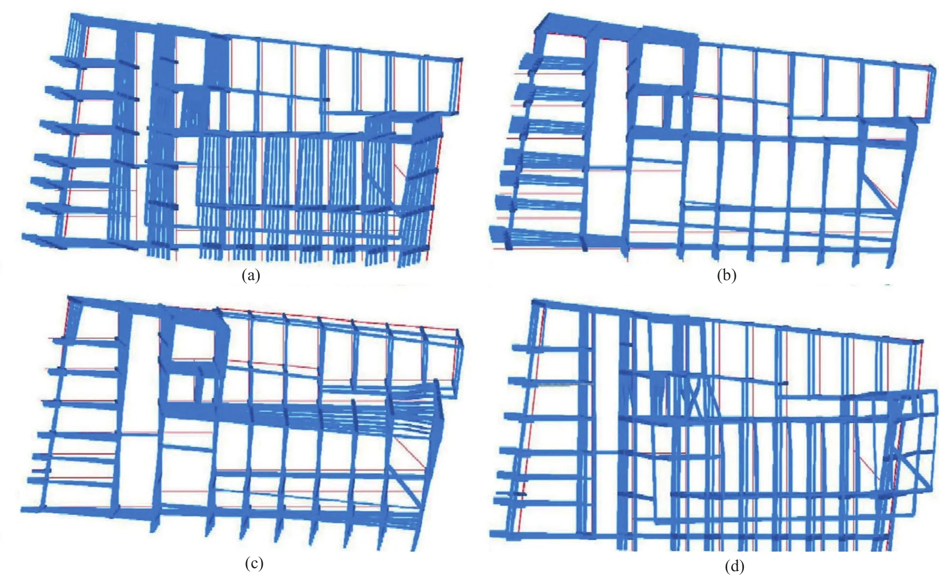
Fig.9 Mode shapes of the existing building: a) 1st mode shape; b) 2nd mode shape; c) 3rd mode shape; d) 4th mode shape

Table 1 Parameters of NiTi-based SMA
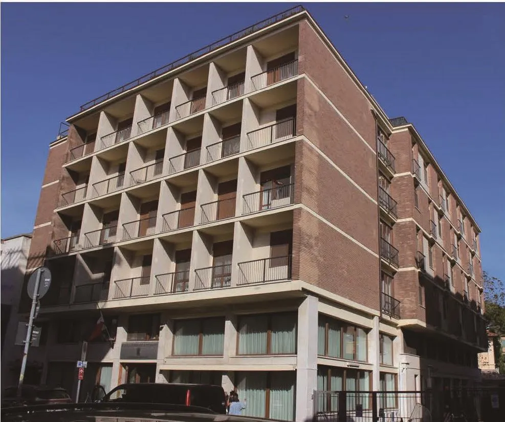
Fig.6 External view of the building
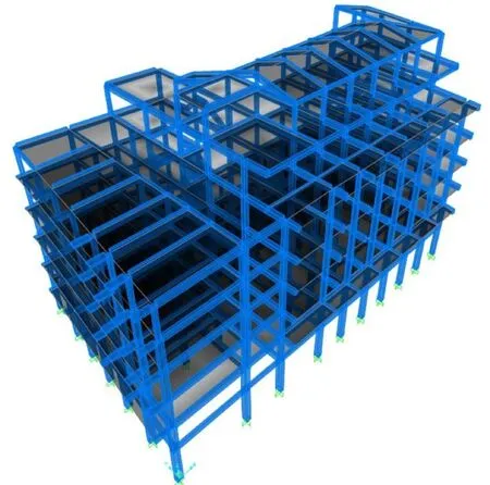
Fig.7 3D model of the building
4 Design of SC-SMA braces
The design of self-centering shape memory alloy(SC-SMA) braces was carried out using a procedure that gave optimal dampers distributions based on themethod first proposed by Kasaiet al.(2004) and then implemented in the JSSI Manual (2007).More details about the design procedure can be found in Ferraioliet al.(2021).In this paper, this procedure, originally proposed for elasto-plastically damped systems, was applied for the design of SMA dampers that exhibited flag-shaped hysteresis loops.At first, a preliminary pushover analysis of the existing building was carried out using a linear elastic first-mode distribution of lateral forces.In general, this choice could be questionable since existing pre-seismic code buildings are often irregular in plan or elevation.Therefore, the higher mode effects in the plan(torsion) and elevation can be considerable (Ferraioli,2015).Moreover, the structure enters an inelastic state during pushover analysis and can exhibit local or soft story mechanisms.Therefore, the linear elastic mode shapes may be not representative of the nonlinear response of the building (Ferraioli, 2017; Ferraioliet al.,2016; Ferraioli and Lavino, 2018).However, it must be highlighted that for the case study herein, these effects are negligible since the first mode is dominant and no local or soft story mechanisms occur.Figure 10 shows the pushover curves (i.e., story shear force vs inter-story drift) of the bare frame structure.It should be observed that floors 1 and 2 were not considered since the design retrofit includes the addition of RC shear walls in the first two stories.In the same way, the eighth floor was not included in the design procedure since the SC-SMA bracing of an attic floor is not necessary.Figure 11 shows the trilinear model of pushover curves that are idealized using the degrading Takeda model (1970) by employing the following hypothesis: a) elastic stiffness equal to the initial tangent stiffness of the pushover curve; b)zero post-yield stiffness; c) the equal energy criterion.Figure 12 shows the simplified trilinear model of the pushover curves obtained by considering the same yield displacement and the same maximum displacement for all the floors, calculated as the average of the values for each floor.The frame system (Fig.13(a)) was idealized using a simplified MDOF system (Fig.13(b)) by which each story is characterized by mass (mi), a total height above the top of the rigid basement (Hi) (Table 5), and a simplified trilinear pushover curve (Fig.12).This MDOF system was then idealized as an equivalent bilinear SDOF system (Fig.13(c)) with equivalent height (Heq=10.59 m) and mass (Meq=1648.75 kN.s2/m),calculated using the following relations:
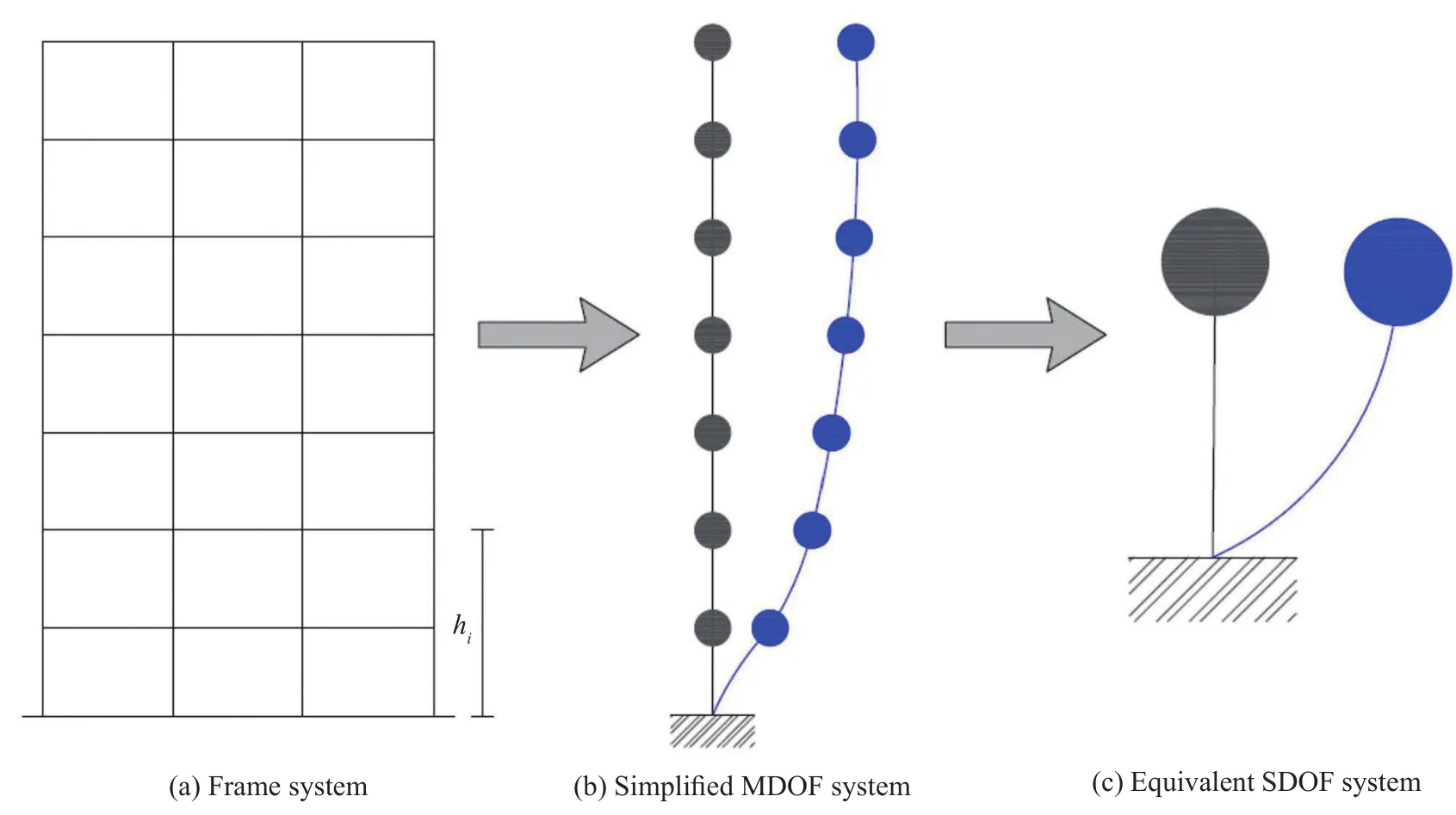
Fig.13 Frame building modeling
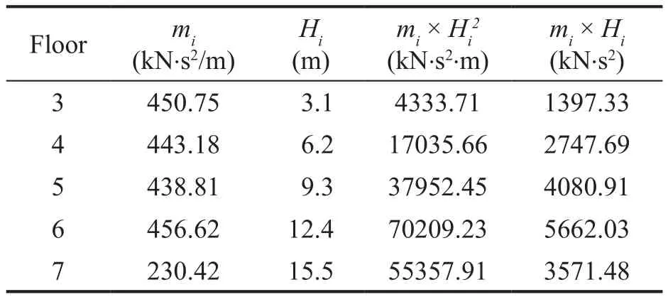
Table 5 Story mass and height

Fig.12 Simplified trilinear pushover curves.a) Pushover in the X-direction; b) Pushover in the Y-direction
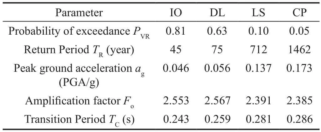
Table 2 Parameters of elastic response spectra (NTC, 2018)

Table 3 Periods, frequencies, and modal mass ratios
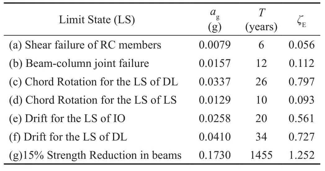
Table 4Capacity peak ground acceleration (ag), and corresponding return period (T) and safety index (ζE)
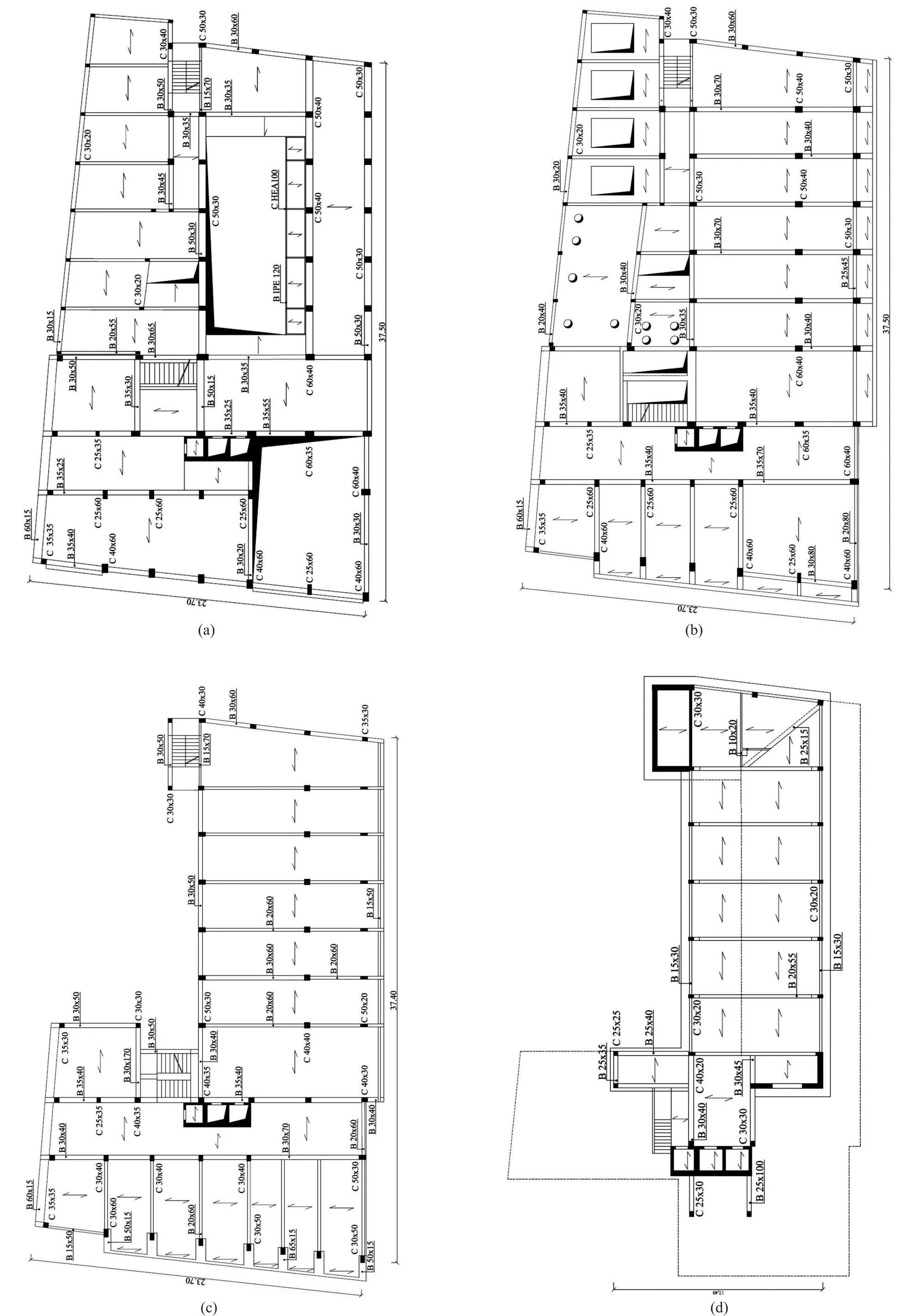
Fig.8 Plan view of a) 1st floor; b) 2nd floor; c) 3rd, 4th, and 5th floors; d) 8th floor

whereuiis the first mode displacement at thei-th floor.
The secant periodof the equivalent SDOF system and the corresponding displacement demanduowere calculated as follows:
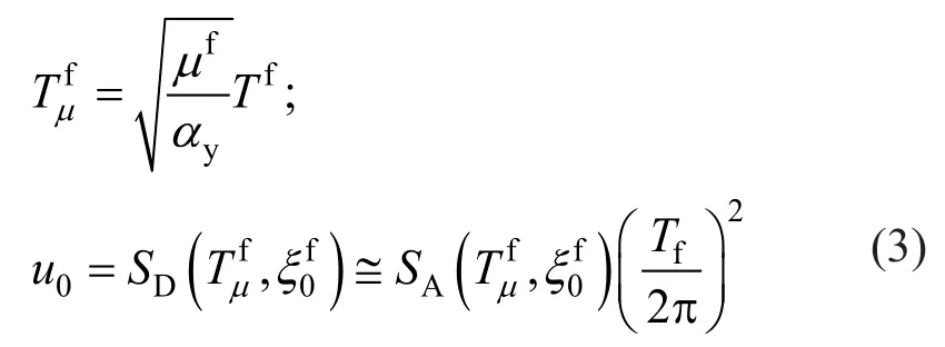
whereTfis the fundamental period,μfandayare,respectively, the ductility ratio and the post-elastic to elastic stiffness ratio;u0is the displacement of the MDOF model at the equivalent height;Heq,SDandSAare, respectively, the spectral displacement and spectral acceleration of the equivalent SDOF system; andis the equivalent viscous damping of the frame system.The equivalent SDOF system of the frame building is the starting point for designing the equivalent SDOF system of the SC-SMA braces (Fig.14(a)).For this purpose, the optimal damper to the RC frame stiffness ratiord=Kd/Kfwas calculated based on the closed-form expression(Kasaiet al., 2004):
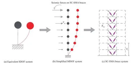
Fig.14 Design procedure of SC-SMA braces

Fig.10 Pushover curves plot: story shear force vs.inter-story drift for each story.a) Pushover in the X-direction; b) Pushover in the Y-direction

Fig.11 Idealized trilinear pushover curves.a) Pushover in the X-direction; b) Pushover in the Y-direction

where the stiffness reduction coefficientp=/Kfis the ratio between the secant and initial stiffness;θf=u0/Heqis the drift angle of the equivalent SDOF system of the frame building;θtis the pre-fixed target drift angle;μcis the cracking ductility ratio of the bare frame;μdis the damper ductility ratio;γsis the steel frame-damper stiffness ratio(γs=0 since no steel frame is used to connect the damped braces to the structure); and finally,a=25,λ=0.5,R=0.6.It should be observed that the ductility ratio demand of dampersμdis unknown.
Thus, an iterative procedure is required.In the first step, the ductility ratio demand of the damperswas assumed to be equal to their ductility ratio capacity.Table 6 shows the design parameters of the SDOF model of the SC-SMA braces.The optimal damper to the RC frame stiffness ratiordhas different values in the two directions (i.e.,rd=1.04 in theX-direction andrd=0.57 in theY-direction) since the period of the equivalent SDOF system of the bare frame assumes different values in theX- andY- directions.The optimal stiffness distribution along the height of the building was selected based on the following assumptions: a) a uniform distribution of the yield drift angle of the dampers; b) a uniform distribution of the drift demand of the dampers; c) an equal equivalent viscous damping ratio for MDOF and SDOF systems.This provides the following distribution rule of lateral stiffnessKd,iof the damped braces (Sutcuet al.,2014):

whereViandQiare, respectively, the design shear force and lateral force at thei-th story, whileis the secant stiffness of the bare frame at thei-th story.Figure 15 shows the distribution of lateral stiffness for the height of the building in theX- andY-directions.The building case study is a lower-deformed type of building, since drift in the lower stories increases.In this case, the design procedure provides a lateral stiffnessKd,iof the damped braces that progressively decreases, along with the height of the building, to assure yielding of the SCSMA dampers, even on the highest floors.It should be highlighted that in other case studies the design procedure could impart a negative stiffness of the damped braces in the upper stories.This situation means that the story stiffness of the RC frame in the upper stories is too high,thus preventing the yielding of damped braces.The design strength of the damped braces at thei-th story was calculated as follows:

Lateral stiffness (Kd,i) and strength (Vd,i) define the simplified MDOF model of the damped braces (Fig.14(b)).The axial stiffness () and strength () of the j-th damped brace at thei-th floor can be selected to furnish the required design stiffness and strength of the SC-SMA brace system (Fig.14(c)), as follows:

whereθjis the inclination angle of thej-th brace andnis the number of the damped braces.The layout inplan of damped braces was selected to increase torsional stiffness of the building, with a minimal impact on architectural functionality (Fig.16).
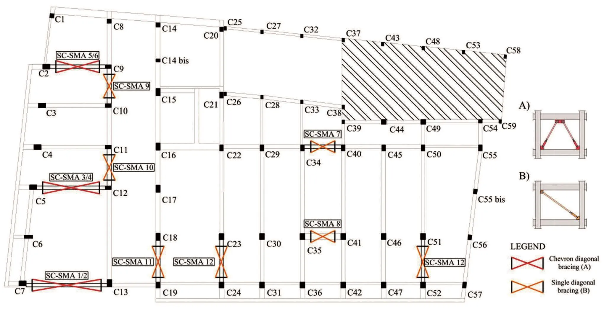
Fig.16 Layout in-plan of the SC-SMA braces
The design lateral stiffness and strength of the SCSMA braces are plotted in Tables 7 and 8, respectively,for theX- andY-directions.The axial stiffness ()of each damped bracte is related to the axial stiffness of the SC-SMA damper () and the brace (), as follows (Fig.3):

The axial strength of the SC-SMA damper is equal to the axial strength of the damped brace (i.e.,=),while the buckling resistance of the brace member in compression was designed according to the capacity design rule to be higher than the strength of the SC-SMA damper so that the dissipation capacity of SC-SMAdampers is not limited by the buckling of the braces.Four types of SC-SMA dampers were considered in the analysis.Their parameters are plotted in Table 9.The parameters of SC-SMA dampers and the corresponding braces are shown in Tables 10 and 11.Figure 17 shows the 3D finite element model of the retrofitted building.The corresponding dynamic properties are plotted in Table 12.In addition to global interventions (i.e., RCshear walls for the first two stories and otherwise SCSMA braces (Fig.18(a)), local elements upgrading was carried out, including strengthening of columns next to the steel braces by steel angles and strips (Fig.18(a)), shear strengthening of unconfined joints with fiber-reinforced polymers (FRP), shear and bending reinforcement of some beams with FRP, and foundation retrofit with micropiles.Figure 18(b) shows the details of the connections of the steel braces to the boundary beams and columns.Finally, it should be highlighted that the design procedure—originally proposed in the literature for hysteretic elasto-plastically dampers—was herein applied to SC-SMA dampers that exhibit flag-shape hysteretic loops.Thus, their energy dissipation capacity may be significantly lower, and their effectiveness for mitigating seismic response should be verified using more refined analysis methods, such as the response history analysis.
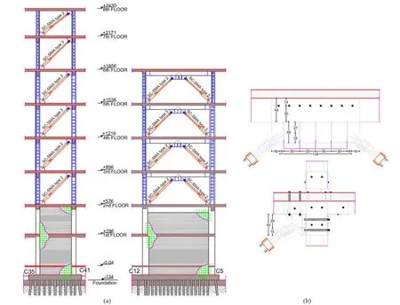
Fig.18 (a) Section views after the retrofit; (b) details of connections of steel brace to RC frame

Table 6 Design parameters of the equivalent SDOF system of SC-SMA braces

Table 7 Design lateral stiffness and strength of SC-SMA braces in the X-Direction
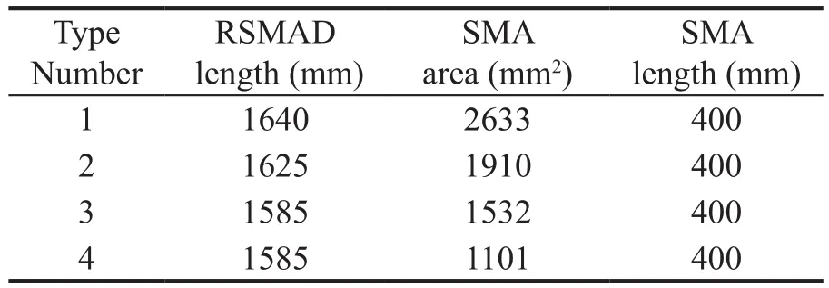
Table 9 Parameters of SC-SMA dampers

Fig.15 SC- Distribution of lateral stiffness over the height of the building.(a) X-direction; (b) Y-direction
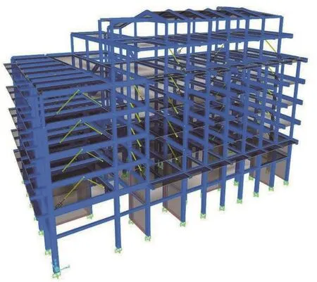
Fig.17 3D model of the retrofitted building
5 Nonlinear time-history analysis for performance evaluation
5.1 Input ground motions
The selection of actual recorded accelerograms is becoming increasingly frequent and more easily accessible since many strong ground motion databases are available in the literature for this purpose.The most effective methods for ground motion record selection are based on seismogenetic features of the sources (i.e.,magnitude (M) and epicentral distance (R), style-offaulting), ground motion intensity measures (IM), soilconditions appropriate to the site, and target spectrum matching (Beyer and Bommer, 2007; Watson-Lamprey and Abrahamson, 2006).Due to the limited number of recorded ground motions, the selection of earthquake records based on the magnitude and epicentral distance for all considered intensity measure (IM) levels is not possible.Therefore, natural earthquake records should be scaled to a target spectrum that is compatible with different IM levels.The amount of scaling has been a controversial topic.The first approach to the problem was based on matching a target value of peak ground acceleration.However, this approach generally gave inaccurate estimates, with a large dispersion in demand parameters.In the same way, other IM parameters (such as effective peak acceleration, effective peak velocity,and Arias intensity) have proven to be inefficient and inaccurate (Kuramaet al., 2003).This paper employs the most commonly applied method for scaling recorded earthquakes.Ground motion records were selected and scaled to match the target spectrum at each hazard level.
The time-domain scaling procedure changes the acceleration amplitude without modifying frequency content or phasing.Similar rules for selecting and scaling ground motion records are provided by many current building codes.This paper applies the ground motion selection and scaling procedures of the Italian Code (NTC-Guidelines, 2018), which are based on EN 1998-1 (2004).A set of seven earthquakes was selected for the life safety (LS) limit state, and another set was selected for the collapse prevention (CP) limit state.The recorded accelerograms were selected applying the spectrum-compatibility rules as defined by EN 1998-1(2004) and using the Rexel computer code (Iervolinoet al., 2010).The parameters of the selected accelerograms are shown in Tables 13-14.Figures 19-20 show the target and average spectrum, and the scaling factors used to satisfy spectrum-compatibility.

Table 10 Design parameters of SC-SMA dampers and braces in the X-Direction

Table 11 Design parameters of SC-SMA dampers and braces in the Y-Direction

Table 12 Periods, frequencies, and modal mass ratios

Table 13 Set of earthquake records for the LS Limit State

Table 14 Set of earthquake records for the CP Limit State
5.2 Seismic assessment
The seismic performance of the RC building retrofitted with the SC-SMA braces was evaluated using the nonlinear time-history analysis, employing flag-shape hysteretic loops for modeling the SC-SMA dampers to adequately reproduce the behavior of the structure in the range of deformations and velocities typical of the seismic response.Two simultaneously acting accelerograms representing the two horizontal components of earthquake ground motion were considered in the analysis.Figure 21 shows the peak floor acceleration demand over the height of the building,retrofitted with SC-SMA braces.The results are plotted in both theXandYdirections and refer to three columns(namely C1, C7, and C55, shown in Fig.16).Both the mean (μ) and mean (μ)+standard deviation (σ) values of the peak acceleration response are plotted.The plot indicates a nearly constant trend for the first two stories where the RC shear walls are located, while peak floor acceleration increases at higher floors.Figures 22-23 show the variation in the peak inter-story drift ratio(IDR) response over the height of the retrofitted building(Fig.22) and the existing building (Fig.23) under all the ground motions considered for the life safety (LS) limit state.Story levels 1 and 2 are not plotted since the design retrofit includes the addition of RC shear walls in the first two stories.Consequently the corresponding interstory drifts are very low.A more uniform distribution of the IDR response is observed over the height of the retrofitted building compared with the existing building.In this case, the maximum IDR response is noted for the1st and 2nd stories.Moreover, the retrofitted building exhibited a peak IDR response that never exceeded the maximum allowable transient drift, taken as 2%corresponding to the performance objective of collapse prevention.
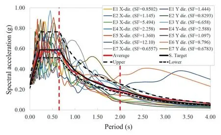
Fig.19 Spectrum compatibility of records for the LS Limit State
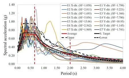
Fig.20 Spectrum compatibility of records for the CP Limit State
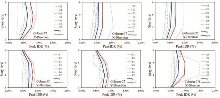
Fig.22 Variation of peak inter-story drift response (IDR) over the height.Retrofitted building
On the contrary, the existing building exhibited the maximum IDR value, exceeding 2%, noted for only one ground motion in theX-direction, and two ground motions in theY-direction.Figures 24-25 show the variation in peak residual Inter-story drift response (RIDR) over the height of the retrofitted building (Fig.24) and the existing building (Fig.25) under all the ground motions, together with the mean (μ) and mean (μ)+standard deviation.The residual Inter-story drift ratio (RIDR) response is found to be negligible for the building retrofitted with SC-SMA dampers (Fig.23).Moreover, a more uniform distribution of RIDR response is observed over the height of the retrofitted building compared with the existing building.On the contrary, the RIDR response is not negligible for the existing building, and it is not uniform but maximum at the first story.The maximum value of RIDR noted for the existing building is found to be 0.34% for column C1 in theX-direction.In this case, the maximum value of mean + standard deviation peak RIDR response is found to be in the range of 0.1%-0.2%.Verification of safety under earthquake loading was carried out according to the Italian Building Code (2018).The limit states of collapse prevention and life safety were consideredin the analysis.The collapse prevention verification compares the displacement ductility demand of the hysteretic dampers to the corresponding displacement ductility capacity.
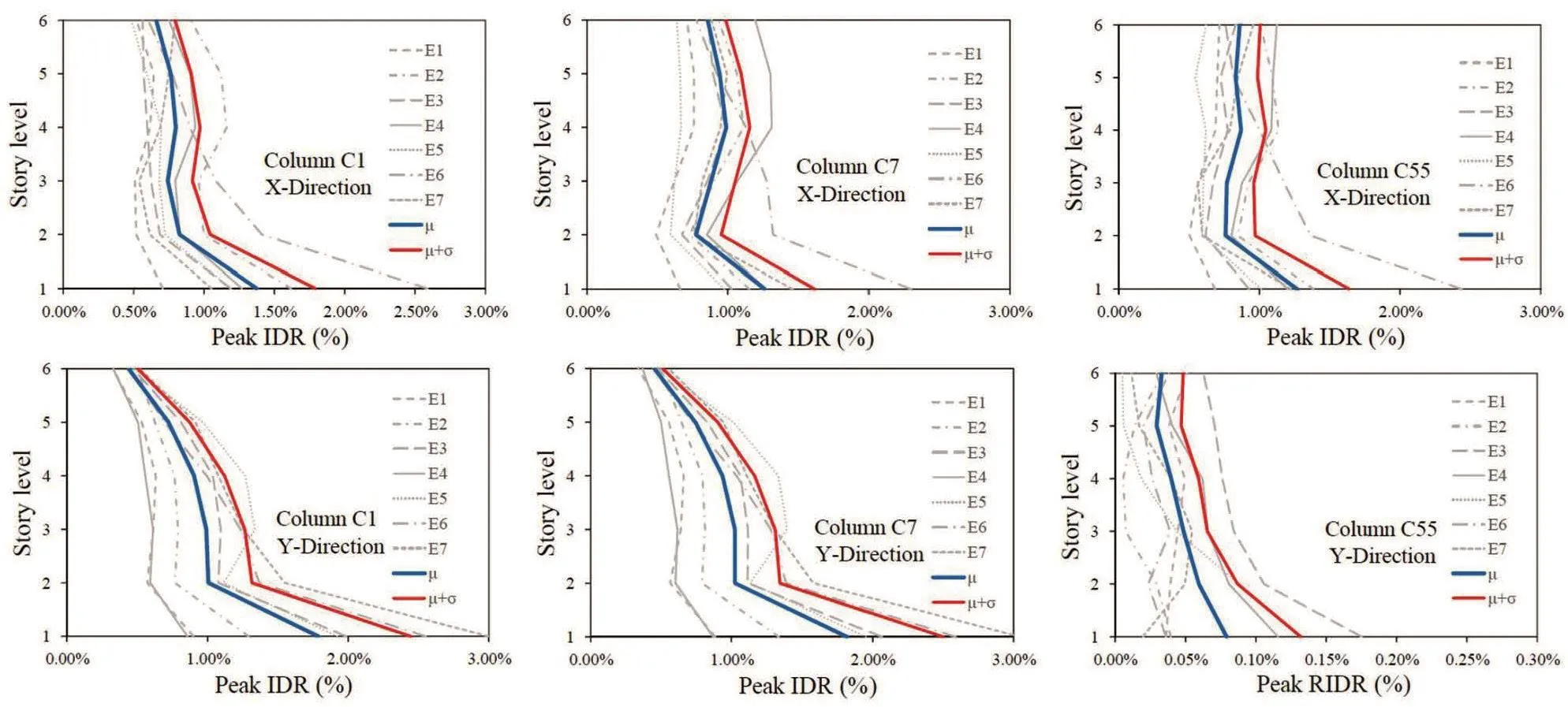
Fig.23 Variation of peak inter-story drift response (IDR) over the height.Existing building
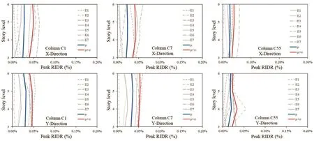
Fig.24 Variation of peak residual drift response (RIDR) over the height.Retrofitted building
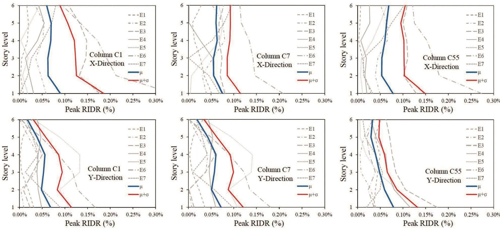
Fig.25 Variation in peak residual drift response (RIDR) over the height.Existing building
Figures 26-27 show the hysteresis loops of the SMA dampers under the seven time-histories considered for the collapse prevention limit state.Table 15 shows the mean of the peak values of the displacement response for seven individual earthquakes.This value was used as the design value of the seismic effect according to the Italian Code (NTC-Guidelines, 2018).The results show that the design procedure is effective for ensuring an almost uniform yielding of SC-SMA dampers.Life Safety verification compares the member chord rotation demand to the corresponding chord rotation capacity.For columns, inter-story drift can be used instead of chord rotation.The nodal rotation due to seismic loading is low compared to the drift (Δ) of the equivalent cantilever.Thus, the chord rotationθmay be calculated asΔ/Ls, whereLsis the shear span length (assumed to be equal to half the member).In bi-axial bending, the drift capacity depends on the direction of the bending axle.However, the interaction diagram may be assumed to be circular if the components of chord rotation along the sides of the section in bi-axial bending are normalized to the corresponding chord rotations in uniaxial loading (Fardis, 2009).Therefore, the capacity may be represented through a limit domain on theXinter-story drift -Yinter-story drift plane (Fig.28).The damage limitation (DL) limit domain was plotted from the chord rotation at yielding (θy), calculated from EN 1998-3(2005).The life safety (LS) limit domain was plottedfrom 3/4 of the ultimate chord rotation (θu) defined by the formula A.1 of EN 1998-3 (2005).Figure 28 compares the inter-story drift capacity with the corresponding demand under the seven earthquake ground motions considered for the life safety limit state.Figure 28 shows that the seismic demand corresponding to each of theseven earthquake ground motions considered for the limit state of life safety (LS) never crosses the LS limit domain.This means that the chord rotation capacity of the columns for the limit state of life safety is never exceeded.Moreover, only for some columns, seismic demand slightly exceeds the damage limitation (DL)limit domain.These results highlight that, if properly designed, the SC-SMA damped braces are effective in mitigating inter-story drifts and minimizing structural damage under strong earthquake ground motions by means of their energy dissipation capacity.Moreover,when compared to other retrofit design strategies, the SC-SMA braces have the advantage of returning to their initial position (Figs.26-27) and act to self-center the structure, leaving no residual drifts.This is an important property that makes the structure repairable even after strong earthquake ground motions by reducing the postearthquake residual deformations and, thus, repair time and cost.This is due to perfect modeling of the SC-SMA braces.As previously mentioned, the AF-SAP model used in this paper is has some limitations.However,despite the aforementioned simplifying hypothesis,the results are expected to be reproduced in a complete approach.
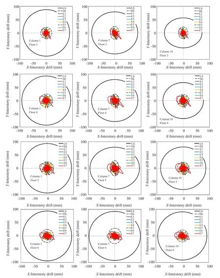
Fig.28 Drift time-histories and limit domains

Table 15 Displacement of SC-SMA dampers for the Limit State of Collapse Prevention
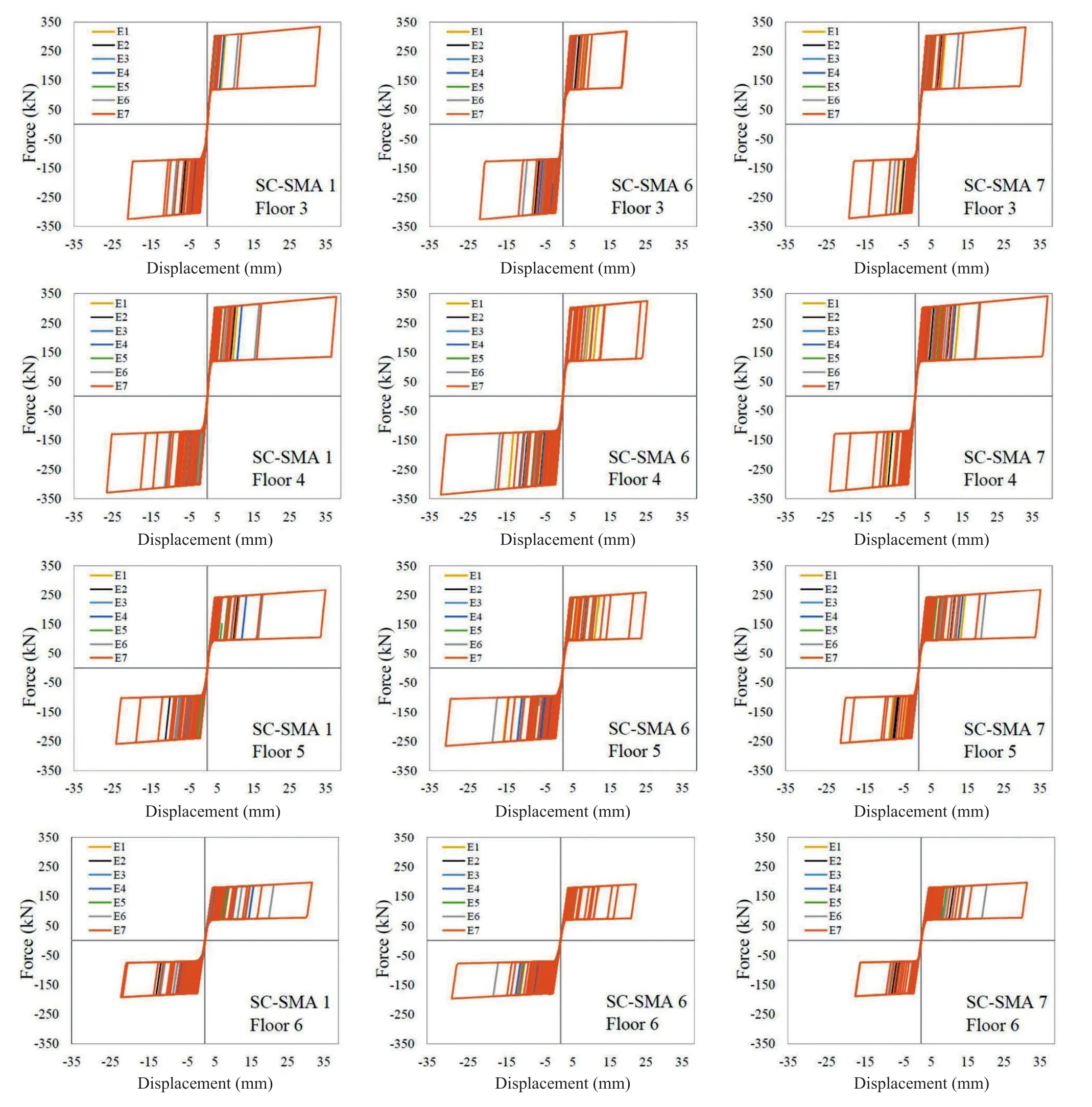
Fig.26 Hysteresis loops of SC-SMA dampers in the X-direction.Collapse prevention limit state
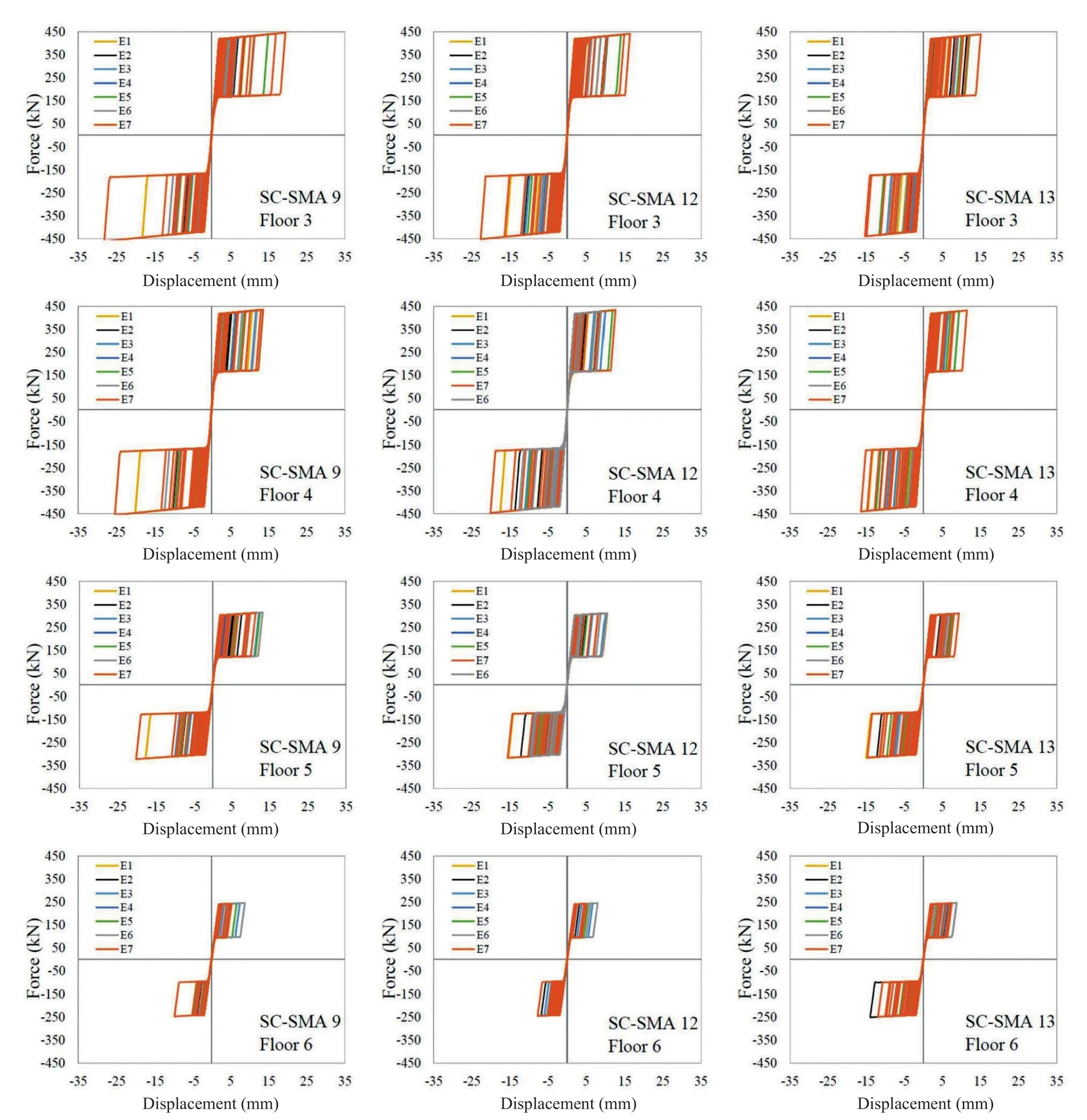
Fig.27 Hysteresis loops of SC-SMA dampers in the Y-direction.Collapse prevention limit state
6 Conclusions
Applications of self-centering shape memory alloy braces to complex actual RC buildings, as well as simplified approaches for practical designs, are still lacking in the literature.This paper implements a design procedure based on decomposing the dual RCSMA braces system into two subsystems and applying an optimal damper distribution rule.The complex nonlinear response of a full-scale complex RC building retrofitted with SMA braces is investigated, and results are presented and discussed in detail.
Based on the above analyses, the following conclusions can be drawn.
- The design procedure, originally proposed for elastoplastic dampers, is shown to be feasible and alsoeffective for SMA dampers with flag-shaped behavior.
- Based on the results from the nonlinear dynamic analysis, the RC building retrofitted with SMA braces is shown to respond according to the predictions of the design method.
- The flag-type hysteretic loops, under the influence of seven different earthquake ground motions,show that the optimal damper distribution rule ensures an almost uniform yielding of SC-SMA dampers.
- The recentering shape memory alloy bracing system, applied to a complex RC building structure,has proven its effectiveness in mitigating maximum transient inter-story drifts and minimizing structural damage.The seismic demand of the columns under the earthquake ground motions at the life safety level is well below their life safety capacity and slightly exceeds the damage limitation capacity.
- The self-centering capability of the SMA braces reduces residual inter-story drifts and allows the columns to recover their original position, making them repairable even after strong ground motions.
Finally, it should be highlighted that the design procedure is based on several simplifying assumptions.First, the SDOF assumption neglects both torsional and higher-mode effects.Thus, it is valid for normal low-rise buildings but may fail for irregular or highrise buildings.Then, the dual RC-SMA braces system is decoupled into two subsystems, thus neglecting both global and local interactions and underestimating local forces due to bracing.Finally, the same maximum and yield displacements are assumed for all stories, thus neglecting that the existing buildings may exhibit softstory or torsional failure mechanisms.Thus, further research is required to address these limitations.
Acknowledgement
The authors wish to express their most sincere gratitude to Eng.Gennaro Di Lauro and all the professional team belonging to Aires Ingegneria for their invaluable support during the on-site activities.
杂志排行
Earthquake Engineering and Engineering Vibration的其它文章
- Property estimation of free-field sand in 1-g shaking table tests
- Dynamic p-y curves for vertical and batter pile groups in liquefied sand
- Underground blast effects on structural pounding
- Seismic bearing capacity of strip footing on partially saturated soil using modal response analysis
- An analytical model for evaluating the dynamic response of a tunnel embedded in layered foundation soil with different saturations
- Controlled rocking pile foundation system with replaceable bar fuses for seismic resilience
