Weakly Singular Symmetric Galerkin Boundary Element Method for Fracture Analysis of Three-Dimensional Structures Considering Rotational Inertia and Gravitational Forces
2022-07-02ShuangxinHeChaoyangWangXuanZhouLeitingDongandSatyaAtluri
Shuangxin He,Chaoyang Wang,Xuan Zhou,★,Leiting Dong,★and Satya N.Atluri
1School of Aeronautic Science and Engineering,Beihang University,Beijing,China
2Department of Mechanical Engineering,Texas Tech University,Lubbock,USA
ABSTRACT The Symmetric Galerkin Boundary Element Method is advantageous for the linear elastic fracture and crackgrowth analysis of solid structures,because only boundary and crack-surface elements are needed.However,for engineering structures subjected to body forces such as rotational inertia and gravitational loads,additional domain integral terms in the Galerkin boundary integral equation will necessitate meshing of the interior of the domain.In this study,weakly-singular SGBEM for fracture analysis of three-dimensional structures considering rotational inertia and gravitational forces are developed.By using divergence theorem or alternatively the radial integration method,the domain integral terms caused by body forces are transformed into boundary integrals.And due to the weak singularity of the formulated boundary integral equations,a simple Gauss-Legendre quadrature with a few integral points is sufficient for numerically evaluating the SGBEM equations.Some numerical examples are presented to verify this approach and results are compared with benchmark solutions.
KEYWORDS Symmetric Galerkin boundary element method;rotational inertia;gravitational force;weak singularity;stress intensity factor
Nomenclature
EYoung’s modulus
νPoisson’s ratio
μShear modulus
ρDensity
giGravitational acceleration
ωiAngular velocity
1 Introduction
The Symmetric Galerkin Boundary Element Method (SGBEM) [1–3] has gained increasing popularity in fracture and crack-growth analysis of solid structures due to its attractive features of symmetric coefficient matrices,weak-singularity,and that only boundary &crack-surface elements are needed.The papers by Bonnet et al.[3–5] are devoted to the formulation,numerical evaluation and implementation of SGBEM.Atluri et al.[6–9] utilized a simple and straightforward methodology to develop regularized traction Boundary Integral Equations (tBIE) for two and three-dimensional linear-elastic solids containing cracks,and also developed weakly-singular SGBEMs for the fracture and fatigue analysis of various complex structures.However,for the fracture mechanics problems such as turbine discs and turbine blades of aircraft engines,concrete gravity dam,etc.,SGBEM may lose its advantages,because evaluation of domain integral terms resulting from body forces such as rotational inertia and gravitational loads leads to the meshing of the interior of the domain.For this reason,a method to evaluate such domain integral terms using only boundary meshes,is desired to efficiently analyze cracked structures considering body forces with SGBEM.
For the conventional collocation boundary element method based on Somigliana’s identity for the displacement vector,a few methods were developed for this purpose.Considering centrifugal loads presented in rotating gas turbines,Cruse et al.[10,11] transformed domain integrals to boundary integrals by utilizing the divergence theorem.By making use of the Galerkin vector or the Green’s second identity,Danson [12] transformed the volume integral terms to boundary integral terms,for three kinds of body forces,i.e.,gravitational loads,the rotational inertia and steady-state thermal loads.Gao [13] also developed a radial integration technique and applied it to deal with various body forces.Brebbia et al.[14] developed the dual reciprocity method [15]which converts the associated domain integrals into boundary integrals by using a series of basis functions to approximate the body force fields.Brebbia et al.[16] extended the idea of dual reciprocity and proposed another approach,multiple reciprocity method.
Different from the conventional collocation boundary element method [17–19] based on the Somigliana’s identity,formulations of SGBEM [5,8,20] result in weak-form displacement Boundary Integral Equations (dBIE) and weak-form traction Boundary Integral Equations (tBIE).As a matter of fact,the domain integrals caused by body forces appear both in dBIE and tBIE.Moreover,it is beneficial to use tBIE to derive weak-form equations on crack-surfaces,where displacement discontinuities are to be solved as unknowns [5].Thus,if SGBEM is utilized for linear fracture analysis of cracked structures,while for domain integrals appearing in dBIE,one may refer to the above-mentioned transformation techniques,the treatment for domain integral terms appearing in tBIE needs further study.
This paper presents the weakly singular traction boundary integral equation for solids undergoing rotational inertia and gravitational Loads.By using the divergence theorem (div) or the radial integration method (RIM),domain integrals induced by rotational inertia or gravitational forces are transformed into boundary integrals correspondingly.The derived formulas show that these transformed boundary integral terms have no influence upon the coefficient matrix of SGBEM,but only affect the right-hand-side vector.The transformed boundary integral terms derived by the divergence theorem and radial integration method,possessing 1/rsingularity,is weakly singular.Numerical examples demonstrate that only a few Gauss points are sufficient to evaluate boundary integrals.The developed SGBEM with only weakly-singular boundary integrals are thus applied to simulate various examples of 3D solids with/without considering rotational inertia and gravitational loads.
This paper is organized as follows.In Section 2,transformation from domain integrals induced by gravitational and rotational inertia forces to the boundary integrals by div or RIM respectively is carried out.Some numerical examples for solids undergoing rotational inertia or gravitational loads are presented in Sections 3 and 4 with and without cracks correspondingly.In Section 5,we complete this paper with some concluding remarks.
2 Weakly Singular Galerkin Boundary Integral Equations and Boundary Element Method with Rotational Inertia and Gravitational Loads
Consider a linear elastic,homogenous and isotropic solid undergoing an infinitesimal elastostatic deformation,as shown in Fig.1.Ωis the solution domain of the problem with the boundary∂Ω.ξrepresents the field point at a generic location in Cartesian coordinates.x is the source point of the 3D Kervin’s solution [21] where a unit load in an arbitrary directionpis applied.The displacement fundamental solutionin thejdirection corresponding to this unit load and other kernel functionsderived byare listed in the appendix.One may also refer to other forms of these kernel functions in [5,20].
The symmetric Galerkin formulations of displacement and traction Boundary Integral Equations (d &tBIE) for linear elastic solids can be found in [8].The derivation of the conventional boundary element method and SGBEM [5,8,20] generally ignored body forces.Here,the domain integrals considering body forces are added in the equations:

In the above two equations,if the domain integral or boundary integral is with respect to the field point,the integral domain is denoted byΩξor Γξ,respectively;otherwise for source point,the integral domain is denoted by Sx.up(x)andtp(x)are the displacement and the traction at the source point,respectively.δis the variational symbol which is used to import the Galerkin weight function.fj(ξ)is the body force per unit volume.ni(ξ)is the component of outward unit normal at a field point on the boundary.Dtis a surface tangential operator:

whereerstis the permutation coefficient defined bye123=e231=e312=1;e321=e213=e132=-1;erst=0 if any two of the indices are identical.
In this paper,the domain integral:

appearing in traction boundary integral Eq.(2) considering rotational inertia and gravitational loads is transformed into weakly singular boundary integral,using the divergence theorem or the radial integration method.
The radial integration method is introduced here briefly.For further details,one may refer to [13].Domain integral on the left-hand-side of Eq.(5) with a general functionf (ξ)may be written in Cartesian coordinate system(x1,x2,x3)or in spherical coordinate system(r,θ,φ)with the origin at the source pointPshown in Fig.2.

Figure 2:Cartesian and spherical coordinate systems
In the spherical coordinate system

where
In the spherical coordinate system,the area of infinitesimal elementdS on the spherical surface can be expressed as

If the field point is on the boundary Γ of domainΩ,geometric projective transformation can be established between the spherical surface infinitesimal elementdS and the real boundary surface infinitesimal elementdΓ shown in Fig.3.

whereniis the component of outward unit normal of field point on the real boundary surfacedΓ,riis the Cartesian component ofr,i.e.,


Figure 3:Spherical surface dS and real boundary dΓ
By some derivations,the domain integral can be rewritten as

whereF(r)is evaluated by a radial integration ofR2f (ξ)on the segment linking the source point and the field point,i.e.,

∂r/∂nis the directional derivative at the field point on the boundary,which may be expressed as

where(),idenotes the partial differentiation with respect to the Cartesian component of field point if not otherwise stated.Andr,ican be expressed as

Some useful formulas related tor(r/=0) are listed as follows:

In Subsections 2.1 and 2.2,the domain integral terms with rotational inertia and gravitational loads in tBIE are transformed into weakly singular boundary integral terms by two methods of divergence theorem and radial integration method,respectively.
2.1 Transformation of Domain Integrals with Gravitational Loads to Boundary Integrals
Consider a solid body with a constant mass densityρ,and a constant gravitational fieldgi=const.The body force will also be constant,where

In this section,the body forcefj(ξ)in Eq.(4) is defined as gravitational force.The purpose of this section is transforming the domain integral of Eq.(4) considering gravitational force into the boundary integral.Note that-x)in Eq.(4) is the stress field of Kelvin’s solution:

whereνis the Poisson’s ratio;δabis the Kronecker Delta.
Thus,the constant gravity forcefican be taken outside the integral in Eq.(4).Then we get

2.1.1 Using Divergence Theorem to Transform Domain Integrals with Gravitational Forces
Substitution of Eq.(19) into Eq.(26),we have

Substituting Eq.(22) into Eq.(27),we have

Using divergence theorem and Eq.(16),we can get that

Note that,a singularity of 1/rappears in the boundary integral of Eq.(29).This integral is weakly-singular [8],thus Cauchy principal value integral [22] does not need to be taken into account.The numerical integration method to evaluate this weakly-singular integral is stated briefly in Section 2.3.3.
2.1.2 Using the Radial Integration Method to Transform Domain Integrals with Gravitational Forces
Using radial integration method,Eq.(26) can be rewritten as

where

From Eq.(13) and Fig.2,one can find thatR,iis the cosine betweenrand coordinate axisi,i.e.,R,i=r,i.Thus,R,ican be taken out of this radial integral Eq.(31) directly.Substitution of Eq.(31) into Eq.(30) gives

Note that,when the field point approaches the source point,∂r/∂n→0.Singularity of the boundary integral in Eq.(32) therefore is weaker than that in Eq.(29).
2.2 Transform Domain Integrals with Rotational Inertia to Boundary Integrals
About an analytical expression of the rotational inertial force in detail,one may refer to [19].Here we introduce it briefly.Consider a solid body of uniform mass densityρrotating about one axis with angular velocityωi.For simplicity and without loss of the generality,we consider that the axis of rotation passes through the origin of Cartesian coordinate system shown in Fig.4.
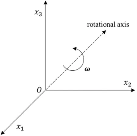
Figure 4:The rotational axis passing through the origin of Cartesian coordinate system
By the D’Alembert’s principle,body force resulting from the rotational inertia is

Eq.(33) may be written in index notation as

where

Note thathjiis constant and can be described in a more straightforward way:

Then this dynamic problem can be treated as an elastostatics problem.Using Eqs.(4),(25)and (34),we get

2.2.1 Using Divergence Theorem to Transform Domain Integrals with Inertial Force
Similar to the derivation of Eq.(28),the inertial force domain integrals with the rotational inertia can be written as

Substituting Eqs.(39) and (40) into Eq.(38) and using Eq.(17),

We get

Then using the divergence theorem,we get


Note that the boundary integrals in Eq.(42) have the property of 1/rweak-singularity.
2.2.2 Using Radial Integration method to Transform Domain Integrals with Inertial Force
Using radial integration method,Eq.(37) may be rewritten as

As is mentioned above,R,jcan be taken outside the integral directly.Note that,F(r)is the radial integral about the field pointξ.Substitution of Eq.(9) into Eq.(44) gives

Note that,for radial integralF(r),source point x is constant.We can directly compute this radial integral.Substitution of Eq.(45) into Eq.(43) gives

Eq.(46) is the boundary integral form with the rotational inertia force obtained by the radial integration method.
2.3 Weakly-Singular SGBEM with Numerical Implementation
We have obtained weakly singular boundary integrals transformed from domain integrals considering rotational inertia and gravitational loads by the divergence theorem or radial integration method.In this section,the displacement and traction boundary integral equations considering crack surfaces and rotational inertia and gravitational loads are given.Then numerical evaluation of weakly singular double layer surface integrals by using quadrilateral elements is introduced briefly.
2.3.1 Traction and Displacement BIEs Considering Rotational Inertia and Gravitational Loads by
Divergence Theorem
Consider a crack embedded in the domainΩshown in Fig.5.The crack surfaces are denoted asS+CandS-Cwhich are geometrically coincident.The outward normal direction ofS+Cis opposite to that ofS-C.With the assumption that the traction acting on crack surfaces satisfies thatt+j+t-j=0,the boundary of the domainΩcan be defined as

whereSuis the part of boundary where displacement is known andStis the part of boundary where traction is known.The displacement discontinuity on crack surfaces may be defined as

whereis the displacement of point x+onis the displacement of point x-onS-C;Δumust be zero around the crack front.Points x+and x-are geometrically coincident.

Figure 5:Displacement discontinuity in domain Ω
If the weak-form traction boundary integral equation is applied onSt,we may get that
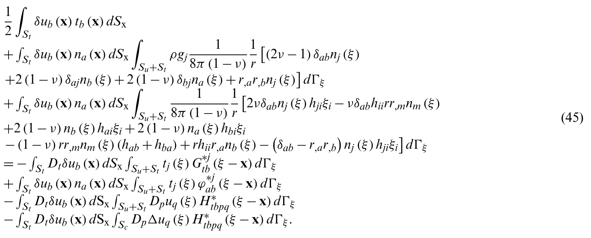
And if the weak-form traction boundary integral equation is applied on the crack surfacesSc,we may get that

Finally,the weak-form displacement boundary integral equation is applied on the prescribed displacement boundary surfacesSu,we may get that

Eqs.(49)–(51) are the weakly-singular traction and displacement boundary integral equations considering rotational inertia and gravitational loads obtained by using divergence theorem.Eandνare Young’s modulus and Poisson’s ratio of the isotropic solid,respectively.Then we may discretize boundary surfaces∂Ωinto boundary elements.Traction field functions can be written in terms of nodal shape functions asatSt;similarly displacement field functions can be written asatSt,where an overline denotes that the nodal variables are known.In this way,the discretized traction and displacement SGBEM equations are obtained,and we denote this method as SGBEM-div in this paper.
2.3.2 Traction and Displacement BIEs Considering Rotational Inertia and Gravitational Loads by the Radial Integration Method
Similar to Eqs.(49)–(51),the weakly-singular traction and displace BIE considering rotational inertia and gravitational loads by radial integration method can be written as follows:
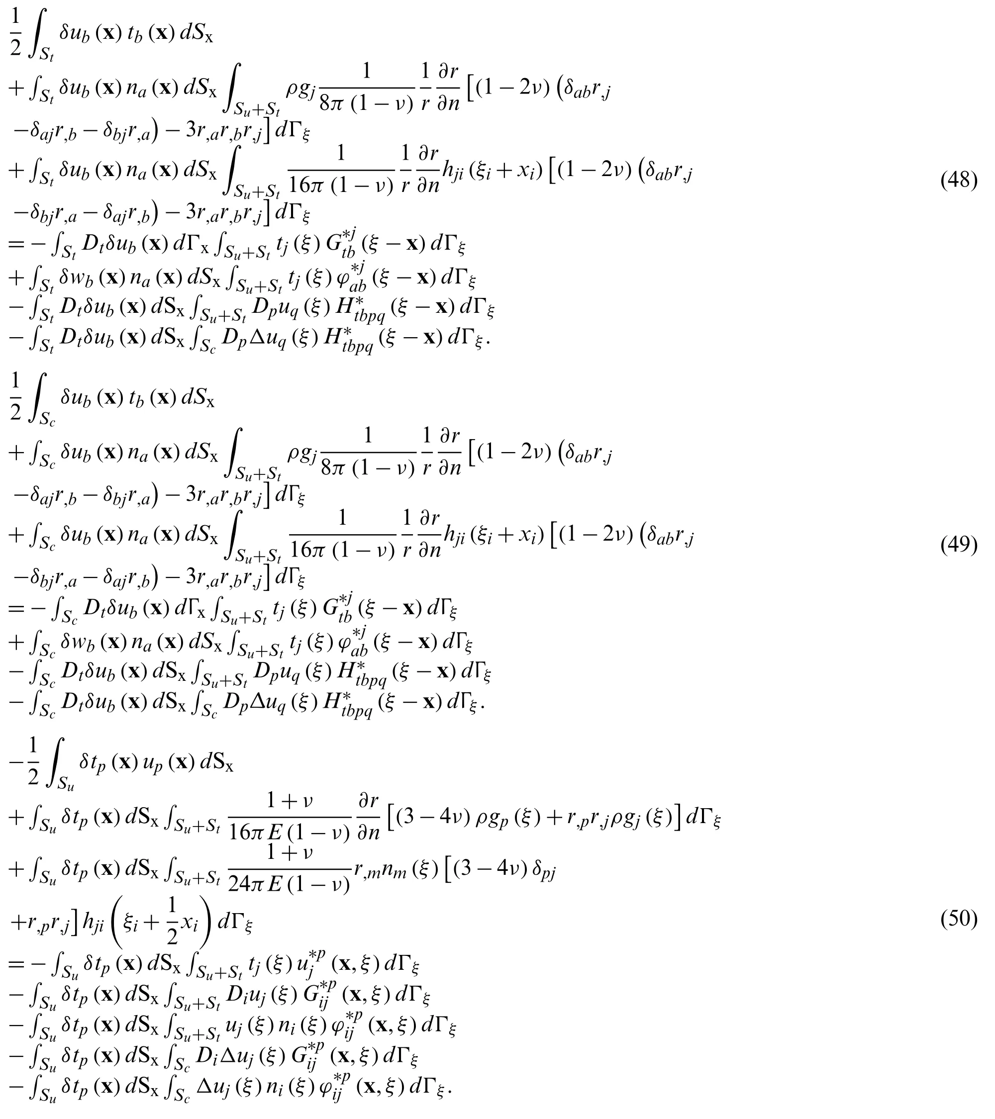
By the same discretization procedure mentioned above for Eqs.(52)–(54),the SGBEM equations obtained by radial integration method can be obtained,and we denote this as SGBEM-RIM in this paper.
It can be seen that,for Eqs.(49),(50) using the divergence theorem,there exists 1/rsingularity in boundary integral terms containing rotational inertia and gravitational loads;while for Eqs.(52),(53) using the radial integration method,there exists 1/r·∂r/∂nin boundary integral terms containing rotational inertia and gravitational loads.As is mentioned above,when the field point approaches the source point,∂r/∂n→0.In other words,by the radial integration method,the obtained boundary integral terms may have weaker singularity compared with those obtained by the divergence theorem.
2.3.3 Numerical Evaluation of Weakly-Singular Double Surface Integrals Using Quadrilateral Elements
In this paper,8-noded quadrilateral isoparametric elements are selected for the numerical implementation,and quarter-point singular quadrilateral elements with two mid-side nodes shifted towards the crack front as shown in Fig.6 are adopted at the crack front.For the numerical evaluation of double surface integrals by quadrilateral isoparametric elements in detail,one may refer to [3],here it is introduced briefly.
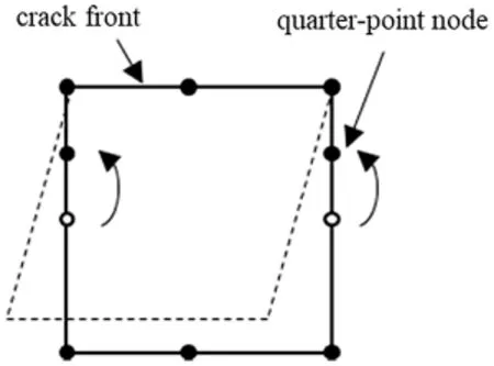
Figure 6:A quarter-point singular quadrilateral element
As shown in Fig.7,there are four quadrilateral elementsA,B,C,D.In the computation of the double layer surface (Sx&Γξ) integrals,two elements will form a pair.One appears in the Sx,while the other appears in Γξ.There exist four kinds of cases: coincident elements,e.g.,Ax&Aξ;adjacent elements sharing one edge,e.g.,Ax&Bξsharing edgepq;adjacent elements sharing one vertex,e.g.,Ax&Cξsharing vertexp;distinct elements,e.g.,Ax&Dξ.Numerical integral for a pair of distinct elements do not need special treatment.But for the first three cases,a coordinate transformation is used for numerical integration,which can introduce a Jacobian exploited to cancel singularity of the boundary integral.
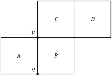
Figure 7:Cases of pairs of quadrilateral elements
For a pair of distinct elements,standard isoparametric coordinate transformation is used together with the standard Gauss-Legendre quadrature.As an example,the double layer surface integral considering gravitational loads obtained by the divergence theorem in Eq.(49) is considered at here.

For simplicity,we rewrite it as

whereare isoparametric coordinates corresponding to Cartesian coordinatesx1,x2,ξ1,ξ2.It should be noted that,in Eq.(56),includes the Jacobians of the coordinate transformation.
For cases of coincident elements,adjacent elements sharing one edge,adjacent elements sharing one vertex,further coordinate transformations are given in below to cancel the singularity caused by 1/rappearing in Eq.(56).
For a pair of coincident elements,local isoparametric coordinates are shown in Fig.8.The boundary integral domain is partitioned into 8 subdomains.For each case we may implement a further transformation of variables listed in Table 1.

Table 1:Transformation of variables for a pair of coincident elements

Figure 8:Isoparametric coordinates for a pair of coincident elements
In Table 1,v1,v2,v3,v4are defined as follows:

The Jacobian for such a variable transformation can be used to cancel the singularity in Eq.(56):

For a pair of coincident elements,Eq.(56) can be rewritten as

For a pair of common-edge elements,local isoparametric coordinates are shown in Fig.9.

Figure 9:Local isoparametric coordinates for a pair of common-edge elements
This boundary integral domain is partitioned into 6 subdomains.For each case we may implement a transformation of variables listed in Table 2.

Table 2:A transformation of variables and Jacobians for common-edge elements
In Table 2,v1,v2,v3,v4,v5andJ1,J2are defined as follows:

Jacobians of the variable transformation are

For a pair of elements with a common vertex,local isoparametric coordinates is shown in Fig.10.
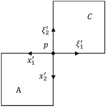
Figure 10:Isoparametric coordinates for a pair of elements with a common vertex
This boundary integral domain is partitioned into 4 subdomains.For each case,a transformation of variables listed in Table 3 is implemented.
Variablesv1,v2,v3,v4are defined as follows:

The Jacobian of the variable transformation can be used to cancel the singularity in Eq.(56):

3 Numerical Examples without Cracks
In this section and the next section some examples without or with crack are implemented respectively to verify SGBEM-div or SGBEM-RIM developed in Section 2.
3.1 Numerical Test of the Effect of the Number of Integration Points
In this section,the double surface integral term in Eq.(55),for a pair of coincident square elements,is evaluated using the quadrature method given in Section 2.3.3,considering the problem of a cube of two kinds of meshes undergoing gravity given in Section 3.2.Fig.11 shows the logarithmic value of the absolute value of relative errors for the numerical integration of both a pair of square elements and a pair of distorted elements.The error is very small when the number of Gauss integration points is larger than 6.Thus,8 gauss points are used for the evaluation of double layer surface integrals in the following examples except for the cube undergoing gravitational loads in Section 3.2.
The effect of the number of integration points is shown in Fig.12,where the relative error is defined as follows: relative error=[I(n)-I(48)]/I(48)×100%,where I(n) is evaluated double surface integral withnGauss points.
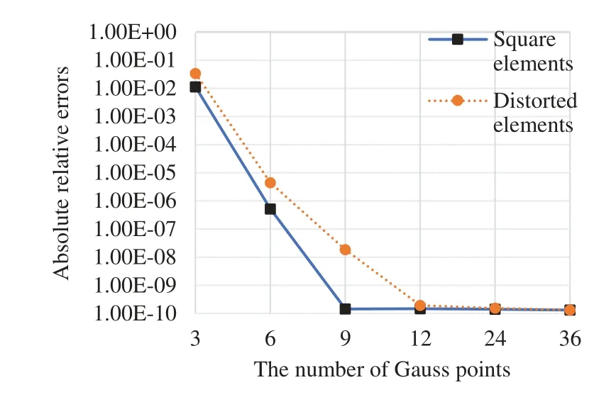
Figure 11:Relative errors for the evaluated weakly-singular boundary integral
3.2 A Cube Undergoing Gravitational Loads
We consider a cube with dimensions of 10 mm×10 mm×10 mm [13],which is discretized into 96 quadratic boundary elements with 290 boundary nodes.Two kinds of meshes of the cube is presented in Fig.12.The surfacez=0 is completely fixed.The elastic constants are chosen to be the Young’s modulusE=1000Mpa and the Poisson’s ratioν=0.
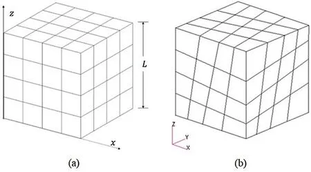
Figure 12:Mesh of a cube (a) elements being square,(b) elements being distorted
The gravitational forceρg3=-10 Mpa/mm is considered.And the analytical solution for the vertical displacement is

Because the analytical solution is only quadratic with respect to z coordinate,3 Gauss points are used for the evaluation of vertical displacements along the directionzshown in Table 4.The computational results of both square and distorted elements are in excellent agreement with the exact solution.

Table 4:Vertical displacements of cube undergoing gravitational loads
3.3 A Rotating Disk
In the second example,a disk with inner radius of 0.1m and outer radius of 0.2 m,rotating at a constant angular speedω=10000rpm(Fig.13),is considered.The thickness of this disk ist=0.02m.The elastic constants are chosen to be the Young’s modulusE=7000Mpa and the Poisson’s ratioν=0.3;densityρ=2800 kg/m3.All the boundary surface of this disk is free from traction.The distribution of displacement in a rotating elastic disk

can be found in [23] whereRis the radial coordinate,Ethe Young’s modulus andνthe Poisson’s ratio.The boundary of the disk is discretized with 3 elements in radial direction,16 elements in circumferential direction,and 1 element in axial direction (Fig.14).4 nodes on the x-y plane highlighted in Fig.14 are fixed in z direction;2 nodes on the x-z plane are fixed in y direction;and 2 nodes on the y-z plane are fixed in x direction.

Figure 13:A rotating disk

Figure 14:SGBEM dense mesh of the rotating disk
Table 5 shows the computed radial displacements with the mesh shown in Fig.14.“Exact”denotes exact solutions by the Eq.(61).For each point,“Maximum error” of SGBEM-div and SGBEM-RIM is computed with the exact solution as the reference.As can be seen,computational results by SGBEM-div and SGBEM-RIM are in excellent agreement with the exact solutions.

Table 5:Radial displacements by SGBEM-div and -RIM (10-3 m)
4 Numerical Examples with Cracks
In this section,numerical examples with cracked solids considering body forces are given.In each example,after obtaining the displacement discontinuities for the quarter-point node using the developed SGBEM method,displacement extrapolation is used to calculate the stress intensity factors.
4.1 A Cuboid Hanging under Its Own Weight with a Through-Thickness Crack
Consider a solid cuboid with a crack of length 2a(see Fig.15) under gravitational loads [24],wherel=4,b=1,h=0.5l,a=0.1,t=0.2,ρg=-10.The elastic constants are chosen to beE=1000 andν=0.

Figure 15:A cracked cuboid hanging under its own weight
Computed stress intensity factors are presented in Table 6,in which “Error” means the relative error between SGBEM–div and FEM solution.For this through-thickness crack,KIresults computed by SGBEM-RIM are in better agreement with the FEM solution.

Table 6: KI for the problem shown in Fig.15
4.2 A Rotating Disk with a through-Thickness Crack
A rotating disk with a through-thickness crack (a=0.03 m) is computed shown in Fig.16.The rotating disk is identical to the disk in Section 3.3.Again,excellent agreement between the computed SGBEM results and FEM results are shown in Tables 7 and 8.

Figure 16:SGBEM mesh of a cracked rotating disk
Table 7:KI of through-thickness crack on rotating disk (MPa)

Table 7:KI of through-thickness crack on rotating disk (MPa)
z/t 0.25 0.5 0.75 SGBEM-div 36.497 36.540 36.494 FEM 36.150 36.303 36.150 Error 0.96% 0.65% 0.95%
Table 8:KI of through-thickness crack on rotating disks (MPa)

Table 8:KI of through-thickness crack on rotating disks (MPa)
z/t 0.25 0.5 0.75 SGBEM-RIM 36.498 36.541 36.495 FEM 36.150 36.303 36.150 Error 0.96% 0.66% 0.95%
4.3 A Rotating Disk with Semi-Elliptic Surface Cracks
This section gives a series of results for a cracked disk in Fig.17 with various semi-elliptic surface cracks,shown in Fig.18.All the parameters of this disk are identical to that of disk in Section 3,except for the semi-elliptic cracks.Various semi-elliptic cracks with a fixed depth (a=0.004 m),and various semi-elliptic cracks with a fixed length/depth ratio (b/a=2),are computed using both SGBEM-div and SGBEM-RIM.

Figure 17:A disk with a semi-elliptic surface crack

Figure 18:Various semi-elliptic cracks with a fixed depth (a=0.004 m),and various semi-elliptic cracks with a fixed length/depth ratio (b/a=2)
For simplicity,we give the stress intensity factor KI at point P,i.e.,the deepest point of various semi-elliptic cracks,as shown in Figs.19,and 20.These results can be used for the benchmark solutions for future studies.

Figure 19:KI at the deepest point of semi-elliptic cracks with a fixed depth (a=0.004 m)

Figure 20:KI at the deepest point of semi-elliptic cracks with a fixed length/depth ratio (b/a=2)
5 Conclusions
In this paper,weakly-singular SGBEM for fracture analysis of three-dimensional structures considering rotational inertia and gravitational forces is developed.By using the divergence theorem (div) or the radial integration method (RIM),rotational inertia or gravitational forces induced domain integrals are transformed into boundary integrals.The derived boundary integral terms with the gravitational and inertial forces are weakly-singular,which only influence the SGBEM right-hand-side vector.
Several numerical examples of solids with and without cracks undergoing body forces are studied.The calculated stress intensity factors and displacements show high accuracy compared with reference solutions.The test of numerical integration also shows that only a small number of quadrature points are needed.
The symmetric Galerkin boundary element method considering gravity and inertia loads presented in this paper appears promising in the fracture analysis of structural components with body forces,such as dams and rotating machineries.Furthermore,with some effort,the methodology given in this study can also be extended to deal with domain integrals for SGBEM with thermoelastic problems,which will be given in a subsequent work.
Funding Statement: The first four authors acknowledge the support of the National Natural Science Foundation of China (12072011).
Conflicts of Interest: The authors declare that they have no conflicts of interest to report regarding the present study.

杂志排行
Computer Modeling In Engineering&Sciences的其它文章
- Analyzing the Urban Hierarchical Structure Based on Multiple Indicators of Economy and Industry: An Econometric Study in China
- Modeling and Analyzing for a Novel Continuum Model Considering Self-Stabilizing Control on Curved Road with Slope
- A Novel Meshfree Analysis of Transient Heat Conduction Problems Using RRKPM
- A Personalized Comprehensive Cloud-Based Method for Heterogeneous MAGDM and Application in COVID-19
- Aggregation Operators for Interval-Valued Pythagorean Fuzzy SoftSet with Their Application to Solve Multi-Attribute Group Decision Making Problem
- A High-Efficiency Inversion Method for the Material Parameters ofanAlberich-TypeSoundAbsorptionCoating Basedona Deep Learning Model
