Effect of Auxiliary Gas Flow Parameters on Microstructure and Properties of Ta Coatings Prepared by Three-Cathode Atmosphere Plasma Spraying
2022-06-30JingCuiHaiyangXiaLangCuiGuangLiu
Jing Cui, Haiyang Xia, Lang Cui, Guang Liu
Abstract: Based on the three−cathode plasma spraying system, tantalum (Ta) coatings were pre−pared on the substrate of CuCrZr alloy. The effects of different auxiliary gas (helium) flow rates on the microstructure, phase composition, mechanical and wear resistance properties of Ta coatings were studied. The results showed that the oxidation degree of the coatings decreases first and then increases with the increase of the auxiliary gas flow. When the auxiliary gas flow rate is 70 L·min-1,the oxidation degree of the coating is the lowest, minimum value of the porosity is 0.21%, and the bonding strength reaches the maximum, 59.3 MPa. At this time, the coating wear rate is 0.001 2 mm3·N-1·m-1 with the best wear resistance. This indicates that the auxiliary gas flow has an important influence on the quality and surface mechanical properties of tantalum coating.
Keywords: plasma spraying; tantalum (Ta) coating; auxiliary gas flow rate; bonding strength; tri−bological property
1 Introduction
Tantalum (Ta) is a very stable, corrosion−resis−tant, wear−resistant, and tough material [1],widely used in electronics, chemicals, aerospace,weapons and biomedical fields. The Ta2O5oxide layer formed by tantalum at high temperature has excellent dielectric properties and becomes an ideal material for high−performance capacitors[2−3]. Tantalum has good biocompatibility with human body, and has good biological activity,which can promote the growth of osteogenesis. It is now considered as an ideal biomedical implant material [4−7]. Tantalum metal has high hard−ness [6], good toughness [8], high melting point.Its oxide Ta2O5has self−lubricating properties, so tantalum is also a promising candidate high tem−perature wear−resistant material [9]. However,due to its special smelting process and high price,the wide application of metal tantalum is restricted. The preparation of tantalum as a coating for surface engineering is a main techni−cal path to promote its wide application.
In recent years, the preparation and perfor−mance of tantalum coatings have also developed[10]. At present, sputtering deposition is mainly used to prepare tantalum coating [9, 11−13]. At the same time, chemical vapor deposition (CVD)[14−15], plasma surface alloying [16], electric spark surface alloying(ESA) [17 ], molten salt electroplating [18], laser selective melting (SLM)[8], cold spraying [19, 20] and other technologies have also been actively tried. Lixia Wang [21], T.Li [22] and A. P. Manso [23] used different pro−cesses to deposit tantalum coating on the surface of the bipolar plate of proton exchange mem−brane (PEM) fuel cells. The results show that the tantalum coating greatly improves the corro−sion resistance of the bipolar plate material, and the contact resistance of the coating interface is much lower than that of the substrate, and it can provide all−round protection to the substrate in a high temperature environment. Karnavskaya [24],Yunsong Niu [11], and Jiayi Zheng [25] studied the ablation behavior of tantalum coatings by laser irradiation, and the results proved that tan−talum coatings have excellent ablation resistance.However, different sputtering deposition pro−cesses generally produce α −Ta, β −Ta, or a mix−ture of two phases. Compared with the tough and ductile α −Ta phase, the β −Ta phase is hard and brittle, and its presence will damage the integrity of the coating under strain [26]. Due to the high melting point of tantalum (2 996°C),laser selective melting and other processes require a great heat output to melt tantalum, which will have a great thermal impact on the substrate.Plasma spraying has the advantages of wide range of spraying materials, high bonding strength, and low thermal impact on the sub−strate in coating preparation, making it widely used in wear−resistant coatings [27, 28 ]. At present, few studies about the preparation of tan−talum coating by plasma spraying process are reported.
In the previous work, our group had done research on Mo coating, and prepared Mo coat−ing with high bonding strength by plasma spray−ing technology [29]. However, considering the brittleness of Mo at room temperature and its easy oxidation at high temperature, three cath−ode plasma spraying technology will be used to prepare tantalum coating in this paper. Using the characteristics of continuous adjustable plasma flame atmosphere, the effect of different auxil−iary gas flow parameters on the bonding strength of the coating and the melting state of the tanta−lum metal powder is studied. Combined with the microstructure and sliding friction behavior of the coating, the service performance of tantalum coating was evaluated comprehensively. It pro−vides a technical reference for the preparation and application of large area high quality tanta−lum coating by plasma spraying.
2 Experimenal Procedure
2.1 Experimental Materials and Plasma Spraying Process
The substrate was CuCrZr alloy with the size of 100 mm×70 mm×10 mm. This metallic material is widely used for electrodes, electric conduction link and other electrical contact components. The main elemental components of the substrate are Cr−0.65, Zr−0.65, Al−(0.1−0.25), Fe−0.05, Si−0.05,P−0.01, Cu balance(mass%). Before the experi−ment, the substrate was cleaned with acetone to remove surface oil stains, and the surface of sub−strate was sandblasted with 24 mesh corundum abrasive. Then the substrate was cleaned by ultrasonic cleaner. The spray powder was selected from pure tantalum powder produced by Ningxia Dongfang Tantalum Industry Co, Ltd.The main impurities in the powder are O−0.075,N−0.008, Fe−0.002, Ni−0.004, Cr−0.003, Si−0.005,Mg−0.004, Nb−0.001, Mo−0.001 (mass%) . This powder was angular powder prepared by airflow shaping after hydrogenation crushing, as shown in Fig. 1, and had a good fluidity, a bulk density of 7.01 g/cm3, powder purity ≥99.8%. The XRD pattern of tantalum powder is shown in Fig. 2(a). It is shown that tantalum powder is rela−tively pure and no other phase has been detected.The median particle size measured by laser diffraction particle size distribution was approxi−mately 27.39 μm, as shown in Fig. 2(b). Before spraying, the powders were placed in a vacuum drying chamber at 80 °C for 2 h to reduce the influence of moisture in the powder on the fluid−ity of powder and the quality of the coating.
The integrated spraying system with three−cathode plasma spray gun developed by Metco of Switzerland is adopted. The plasma gun used in the experiments was a TriplexPro−210 triple−cathode plasma gun. The equipment has the advantages of long plasma spraying time, wide adjustable range of process parameters and high plasma flame stability. In the experiment, argon is used as the working gas, helium is used as the auxiliary gas, and compressed air is used to cool the substrate. The rated power of the gun is 90 kW.It can maintain a stable power output below 75 kW. According to the preliminary tests, a sta−ble tantalum coating will not be formed if the auxiliary gas flow rate exceeds 100 L·min-1due to the power limitation of the equipment. The pow−der feeding rate is set to 55 g·min-1according to the oxidation degree of the coating, the coating preparation rate and the working condition of the powder feeder. The specific process parameters of plasma spraying are shown in Tab. 1.
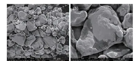
Fig. 1 SEM micrograph of angular Ta powders:(a) the overall shape of tantalum powder; (b)the local enlarged mor−phology of tantalum powder
2.2 Coating Characterization
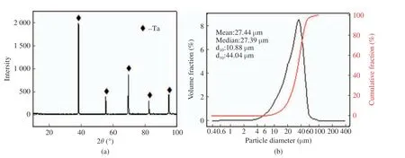
Fig. 2 Tantalum powders: (a)XRD pattern; (b)size distribution

Tab. 1 Plasma spraying parameters
The particle size distribution of tantalum pow−der was analyzed by Zetasizer Nano Z−type laser particle analyzer. The morphologies of the pow−der, as−sprayed coating, and its worn scars were examined by a QUANTA FEG 250−type field emission environmental scanning electron micro−scope (SEM, FEI, USA), equipped with an energy dispersive spectrometer (EDS, OXFORD,England). The phase constituents of the Ta pow−der and the coatings were conducted by X−ray diffraction (Rigaku, Japan) with Cu Kα radia−tion, scanning range 20° -100°, scanning rate 2 (°)/min. Tensile bond strength tests were mea−sured in accordance with the ASTM C633 stan−dard at a tensile speed of 3 mm/min and temper−ature of 20 ℃. The coating and mating parts are bonded with FM1000 glue and placed in a 190 ℃box−type heating furnace for 3.5 h to make them firmly bonded. Three tensile bond strength tests were performed to obtain objective experimental datas by a universal tensile tester. The porosity of the coating was measured by the image method. A total of 10 photographs of the coat−ing were prepared at different locations under each parameter. After binarization, the fraction of the area occupied by the pores of the coating was calculated and finally the average porosity of the whole coating was obtained. The microhard−ness of the coatings was measured by Vickers microhardness tester. The test conditions for the micro−hardness of the coating were as follows: thepressure load was set as 2.941 995 N (0.3 kgf);the holding time was 10 s. The tribological prop−erties of the coating were tested at room temper−ature condition using a ball−on−disc tribometer(UMT−3, BRUKER, USA). The Si3N4ceramic balls with a diameter of 6mm were used as the friction counterpart. The test parameters are given in Tab. 2. Before the test experiment, the surface roughness of the selected samples were reduced to 0.8 μm or less by polishing. This will avoid the experimental errors caused by the roughness of the coating surface. A 3D surface profilometer (Rtec/UP−Lambda, RTEC, USA)equipped with a white light interference lens was used to observe the morphologies of the worn scars.

Tab. 2 Wear test parameters
3 Results and Discussion
3.1 Microstructural Characterizations of the Coatings
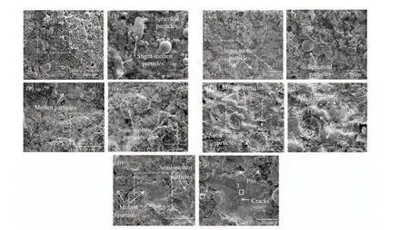
Fig. 3 SEM micro−morphology of Ta coating surfaces at different auxiliary gas flow rates: (a, b) 40 L·min-1; (c, d) 50 L·min-1;(e, f) 60 L·min-1; (g, h) 70 L·min-1; (i, j) 80 L·min-1
Fig. 3 shows the SEM morphology and partial enlarged view of the Ta coating under different auxiliary gas flow parameters. As shown in the figure, the coating surface morphology has three particle deposition morphologies: flat deposition morphology in the overmelting state (Fig. 3(j)),agglomerated particle deposition morphology in the semi−melted state (Fig. 3(f)), and spherical particle morphology in the micro−melting state(Fig. 3(b)). When the auxiliary gas flow rate is 50 L·min-1(Fig. 3(c)), the slightly−melted spher−ical particles on the coating surface decrease, and there are some small areas of over melting flat deposition area; When the auxiliary gas flow rate is 60 L·min-1, the slightly−melted spherical parti−cles on the surface of the coating disappear, and the surface of the coating is mainly in the deposi−tion form of semi−melted agglomerated particles;When the auxiliary gas flow rate is 70 L·min-1,the coating surface is mainly composed of semi−melted agglomerated deposited particles and a large area of overmelted flat deposition area,accompanied by a large number of traces of liq−uid metal splash, and the coating surface is rela−tively flat; When the auxiliary gas flow rate is increased to 80 L·min-1, the coating surface is mainly composed of semi−melted agglomerated deposited particles, the over−melted flat deposi−tion area is reduced, and the coating is rougher.Generally speaking, the powder particles interact−ing with the center of the plasma flame have a higher degree of melting, and the powder parti−cles interacting with the outer edge of the plasma flame have a lower degree of melting, so micro−melting or semi−melting particles are inevitable on the coating surface.
When the semi−molten powder hits the coat−ing at high speed, the coating deposition mecha−nism is mainly based on the pinning effect between particles. From Fig. 3(h) and 3 (g), it can be clearly observed that there are a large number of microcracks in the flat particles on the coating surface. Tab. 3 shows the EDS element content in the corresponding areas in Fig. 3(h)and 3 (g). It is obvious that the oxygen content of the fully melted flat particles is lower than that of the semi−melted agglomerated particles. It is attributed to the high density of the fully melted powder particles. This allows it to have little contact with outside air. The semi−molten powder particles are loosely caked inside and have a large contact area with the outside air. It has a greater chance of being oxidized during the solidification process. This also proves that opti−mizing the powder melting state by spraying pro−cess parameters is beneficial to reduce the oxida−tion degree of the coating and increase the den−sity.

Tab. 3 EDS content on tantalum coating surfaces
The microscopic morphology of the cross−sec−tion of the coating can reflect the density of the coating, the internal defects of the coating and the bonding state of the interface between the coating and the substrate. Fig. 4 shows the microscopic morphology of the Ta coating cross−section under different auxiliary gas flow parame−ters. From Fig. 4(a), 4(b), 4(c), it can be seen that compared with other areas of the coating,the surface layer of the coating has more pores.Due to the hammering effect of the subsequently deposited powder particles, the density of the previously deposited coating is continuously increased. Lots of pores and some vertical cracks can be observed in the loose area of the coating,but no obvious micro cracks are found in the coating. Tab. 4 shows the element content at dif−ferent positions of the coating cross−section. It can be seen that the oxygen content in the lay−ered oxidation zone of the coating is much greater than that of the non−oxidized zone. It is speculated that the oxidation zone contains a large amount of Ta2O5. There is a small amount of copper in the interface occlusal area (point 3),which indicates that the bonding interface may be accompanied by partial metallurgical bonding.
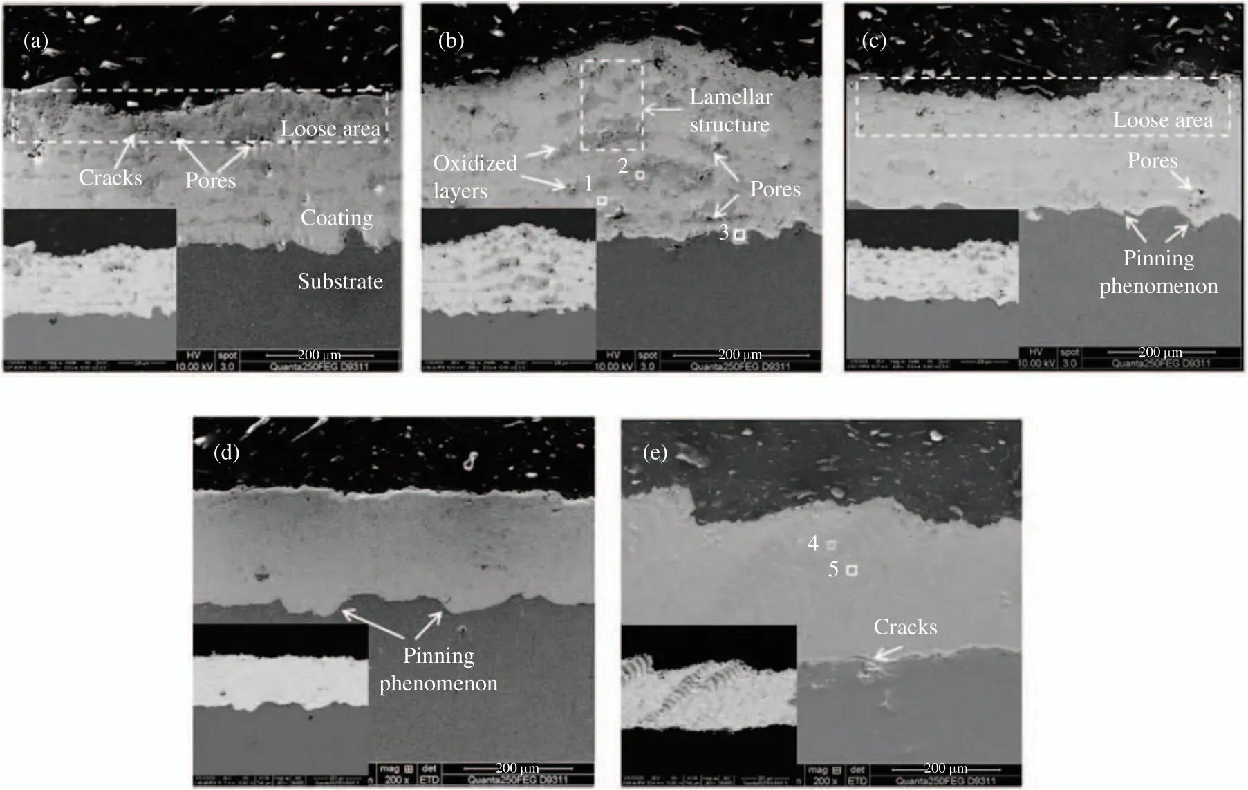
Fig. 4 SEM micro−morphology of Ta coating cross−section at different auxiliary gas flow rates: (a) 40 L·min-1; (b) 50 L·min-1;(c) 60 L·min-1; (d) 70 L·min-1; (e) 80 L·min-1

Tab. 4 The element content at different positions of the coating cross-section
Tab. 5 shows the internal porosity of the coatings measured by the image method. It can be seen that the porosity of the coating first decreases and then increases with the increase in the flow rate of the auxiliary gas He. When the gas flow rate is 40 L·min-1, obvious layered oxi−dation bands can be found in the coating, which are distributed in stripes parallel to the bonding interface of the coating. The oxidation bands can be clearly identified as 6 layers through the backscattered electron image, which coincides with a total of 6 passes during the preparation of the coating. A large number of pores and some cracks exist inside the coating, and the porosity of the coating reaches (1.56±0.57)%. When the gas flow rate is 70 L·min-1, no obvious oxidation zone is found in the coating. The backscattered electron images showed no obvious porosity or cracks in the coating. The denseness of the coat−ing is greatly improved and the upper part of the coating is also denser. The porosity of the coat−ing reaches a minimum of (0.21±0.10)%. When the gas flow rate is 80 L·min-1, the internal oxide content of the coating increases, and the distribu−tion is uneven. The porosity of the coating increased to (0.53±0.06)%. Transverse cracks appear at the bonding interface between the coating and the substrate, causing the coating to have a tendency to peel off.
According to the analysis, it can be known that the layered oxide zone structure is caused by the melting of the powder particles and the cooling process. Tantalum metal will rapidly oxi−dize to Ta2O5above 600 ℃. If the metal powder loses the protection of the inert gas in the flame stream during the spraying process, the oxida−tion of the metallic tantalum on the surface will occur even if it is not cooled below 600 ℃, form−ing an oxidation zone in the form of a laminar distribution. When the auxiliary gas flow rate is 40 L·min-1, the working gas (Ar) and the auxil−iary gas (He) in the plasma spray gun are fully ionized. And an effective protective atmosphere cannot be formed only by feeding the powder gas(Ar). The surface of each layer of tantalum coat−ing is oxidized during the cooling process, thus forming a clear layered oxidation band. As the flow rate of the auxiliary gas (He) increases, the plasma concentration between the cathode and the anode in the plasma spray gun increases,which increases the calorific value of the plasma jet and the degree of powder melting. At the same time the powder particles are accelerated,the molten powder particles stay in the air for a shorter time. The degree of particle oxidation is reduced, and the oxidation zone in the coating is reduced. When the auxiliary gas flow rate is 70 L·min-1, there is enough residual auxiliary gas(He) to protect and cool the newly deposited tantalum coating, which can prevent the tanta−lum coating from contacting the air when the temperature is above 600 ℃, thereby avoiding oxidized; When the auxiliary gas flow rate reaches 80 L·min-1, the gas between the cathode and the anode in the spray gun cannot be com−pletely ionized under the same power, and the ionization degree is reduced. In addition, due to the large flow rate of auxiliary gas, the residual auxiliary gas has a continuous cooling effect on the plasma jet. This makes the calorific value of plasma jet decrease, and then the melting degree of powder decrease. As a result, the residual stress at the bonding interface is too large, which causes cracks and affects the bonding strength of the coating. It is consistent with the analysis of the change of particle deposition morphology on the coating surface. Therefore, the cases of the auxiliary gas flow rate exceeding 80 L·min-1will not be considered in this study.

Tab. 5 The internal porosity of the coatings
3.2 Phase Analysis of the Coatings
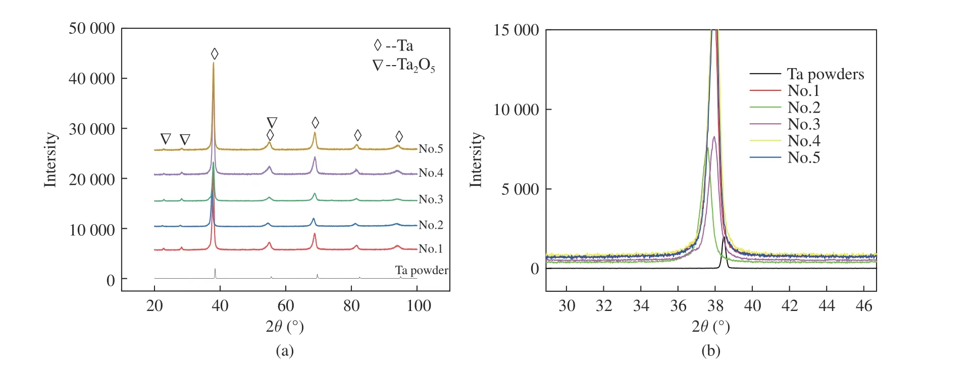
Fig. 5 XRD of plasma sprayed tantalum coating:(a) XRD analysis of tantalum powder and different tantalum coating samples; (b)partial enlarged view
Fig. 5 shows the XRD pattern (Fig. 5(a)) and partial enlarged view (Fig. 5(b)) of tantalum powder and different tantalum coating samples.It can be seen from Fig. 5(a) that the plasma sprayed Ta coating is mainly composed of Ta and Ta2O5phases, and the tiny diffraction peaks at 23° and 28° are Ta2O5phases. This shows that the tantalum coating prepared by plasma spray−ing has less oxide content, and the tantalum phase in the coating has obvious (110) crystal plane preferred orientation. (110) The crystal plane is the most densely packed plane of α−Ta with the bcc structure and has the lowest energy,which allows atoms to grow rapidly in this direc−tion. Therefore, the tantalum grains have a pre−ferred orientation in this direction during solidifi−cation. It can be seen from Fig. 5(b) that com−pared with the original tantalum powder, the sprayed tantalum has a broadening of diffraction peaks. In the process of rapid cooling of the pow−der droplets, the internal grains cannot grow.According to the Hall−Scherrer formula, it can be known that the grain refinement can cause the diffraction peaks to broaden. At the same time,the tantalum coating melts during the deposi−tion process with rapid cooling and solidification.During this period, the tantalum powder parti−cles undergo violent plastic deformation generat−ing a large number of dislocation slips and lat−tice distortions, which causes thedvalue to become larger, the diffraction peak to shift to the left.
3.3 The Mechanical Properties Analysis of the Coatings
3.3.1 The Micro−Hardness of the Coatings
The hardness of the coating is an indicator that reflects the mechanical properties of the coating,and is of great significance for evaluating the anisotropy of the cross−sectional structure of the coating, the wear resistance and the micro−brit−tleness of the coating. Fig. 6(a) shows the micro−hardness of the plasma sprayed tantalum coat−ing under different process parameters. It can be seen from the figure that the microhardness of the tantalum coating is much greater than that of the substrate. With the increase of the auxil−iary gas flow rate, the hardness of the tantalum coating does not change significantly but all are greater than 560 HV0.3. When the auxiliary gas flow rate is increased to 60 L·min-1, the coating hardness exceeds 590 HV0.3. When the auxiliary gas flow rate continues to increase, the coating hardness does not increase significantly; When the auxiliary gas flow rate is 80 L·min-1, it reaches the highest 596.3 HV0.3, so the hardness of the tantalum coating is not sensitive to the change of the auxiliary gas flow rate. It is known that the hardness of the tantalum metal block is about 100 HV0.3, and the hardness of the tanta−lum coating is much greater than 100 HV0.3. This is due to the strong deformation of the particles,which leads to an increase in the lattice defect and the strength of the particles in the coating.During the deposition process, the solid particles undergo plastic rheology caused by “adiabatic shear instability ” under extremely high stress and strain conditions to cause strong hardening of the coating material, thereby greatly increas−ing its hardness.
3.3.2 The Bonding Strength of Coatings
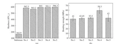
Fig. 6 Mechanical properties of tantalum coatings:(a) the microhardness of tantalum coatings; (b) the bonding strength of tantalum coatings
The bonding strength of the coating is another indicator that reflects the mechanical properties of the coating and the stability of the combina−tion of the coating and the substrate. Fig. 6(b)shows the bonding strength of plasma sprayed tantalum coating under different parameter. It can be seen from the figure that the bonding strength of the tantalum coating first increases and then decreases with the increase of the auxil−iary gas flow rate. The bonding strength of No. 4 tantalum coating reaches 59.3 MPa. Under other parameter conditions, the bonding strength of the tantalum coating does not change much, whose value is between 41-44 MPa. According to the analysis of the microscopic morphology of the coating cross−section, when the auxiliary gas flow rate is 70 L·min-1, the oxidation of the coating is the least and the bonding is good, which shows that the tantalum oxide has an adverse effect on the bonding strength of the coating. When the auxiliary gas flow rate is 80 L·min-1, there are cracks in the bonding interface of the coating to cause mechanical occlusal failure, which greatly reduces the bonding strength of the coating to only 43 MPa. This shows that within a certain parameter range (60 L·min-1-80 L·min-1), the auxiliary gas flow parameter has a greater influ−ence on the bonding strength of the coating.
3.4 Tribological Properties Analysis of Coating
3.4.1 Effect of Auxiliary Gas Flow on the Coef−ficient of Friction of the Coating
Fig. 7 shows the change curve of friction coeffi−cient of different tantalum coating samples with time. It can be seen from the figure that the fric−tion coefficient of No.1, No.2, and No.3 samples have similar changes. The curve of friction coeffi−cient with time can be divided into three periods:running−in period, fluctuate period, steady state period. After the fluctuation period, the friction coefficient of the No.1, No.2 and No.3 sample gradually stabilized at 0.89, 0.83 and 0.81,respectively; However, there was no fluctuation period for sample #4. On the contrary, after a smooth rise to about 0.84, the friction coefficient rapidly decreased to about 0.77, then rose to a maximum of 0.87, and then steadily decreased and stabilized at 0.73; while the friction coeffi−cient of sample #5 rapidly increased 5 minutes after the start of friction. After a period of smooth rise, the friction coefficient first decreased, then increased, and finally decreased smoothly and stabilized at about 0.86.
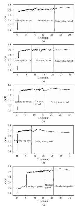
Fig. 7 The change curves of friction coefficient of different tan−talum coating samples: (a) No.1; (b) No.2; (c) No.3;(d) No.4; (e) No.5
The friction coefficient reflects the interac−tion of the coating surface morphology, friction contact mode, load and sliding speed[30]. The analysis shows that in the initial stage of friction,the uneven surface of the coating surface is peeled off by Si3N4ceramics. The coating surface and the end surface of the Si3N4ceramic ball tend to match. When hard abrasive grains of different sizes are embedded in the end surface of the Si3N4ceramic ball, the hard abrasive grains scratch the surface of the sample and scoop out the material to form a furrow. The contact method is from the ball−disk to disk−disk. With the increase of fur−rows, the surface roughness increases, so the fric−tion coefficient gradually increases; With the increase of the friction contact area, under the action of load, No.1, No.2, No.3, No.5 samples fatigue wear of the coating occurs, and part of the coating peels off, resulting in a large change in the roughness of the friction interface,and large fluctuations in the friction coefficient. The peeled coating debris is crushed under the grind−ing action of the ceramic ball, and then dis−charged from the friction interface or stored in the pores in the coating, so that the three−body abrasive particles at the interface are reduced,and the contact surface between the friction pairs becomes smoother and smoother, and then enters a stable state. No.4 sample has a low degree of coating oxidation, fewer internal defects in the coating, dense coating, and better fatigue perfor−mance. Therefore, there is no fluctuation in the friction coefficient caused by partial peeling of the coating, and thus it shows better wear resis−tance.
3.4.2 Effect of Auxiliary Gas Flow on the Mor−phology of the Wear Scar of the Coating
Generally speaking, the hardness of a material is directly proportional to the wear resistance of the material, but it may not be suitable for plasma spray coatings, for the great influence of internal structure and defects of the coating on the wear resistance of the coating. Fig. 8 shows the 3D morphology of the middle part of the friction trace and the cross−sectional profile of the fric−tion trace of different samples. With the increase of the auxiliary gas flow rate, the depth of the friction trace first decreases and then increases.From the 3D morphology, the No. 4 sample has obvious furrows at the bottom of the wear scar,which are typical abrasive wear. The friction trace of the other 4 samples are relatively smooth, which is because the coating has under−gone adhesive wear. Under the action of recipro−cating cyclic load, the coating will undergo plas−tic deformation or shear at the contact point, and the friction surface temperature will rise, causing adhesion at the contact point. The coating is subjected to a large number of tensile cyclic loads, which promotes the failure of the bottom of the wear interface to be transformed into fatigue wear, and the coating material falls off in a large amount. The peeled coating material will cause severe abrasive wear to the coating mate−rial and Si3N4ceramics at the friction interface in the form of three−body abrasive particles, until the abrasive particles are crushed and dis−charged to the grinding interface or embedded in the pits of coatings. The embedding of Si3N4ceramic debris and coating material debris pro−motes smooth wear scar morphology. The form of coating wear failure is: abrasive wear, adhesive wear, fatigue wear, abrasive wear. This cycle causes rapid coating failure. With the increase of the auxiliary gas flow rate, the porosity of the coating first decreases and then increases (as shown in Fig. 8). When the auxiliary gas flow rate is 70 L·min-1, the coating has the least oxi−dation and the coating has the highest cohesive bonding strength. Under the action of friction load, the coating material is not easy to fall off in large pieces, and the form of wear is mainly the furrow formed by the micro−cutting action of fine abrasive particles and ceramic balls. Therefore,the wear scar depth of No. 1, No. 2, No. 3, and No. 5 samples is much greater than that of No. 4 samples.
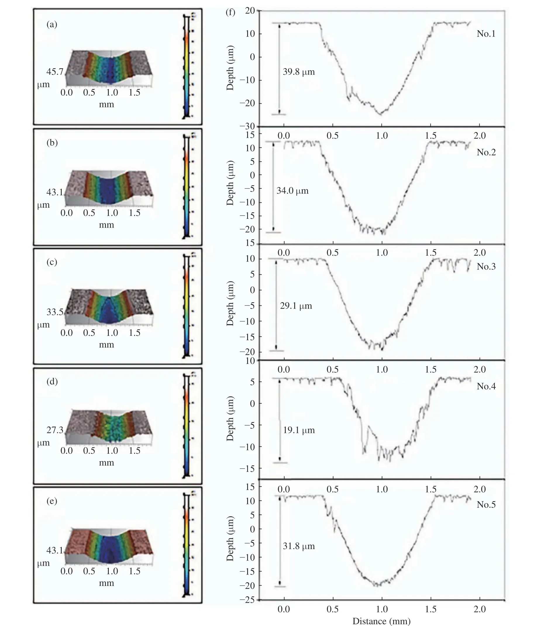
Fig. 8 The 3D morphology of the middle part of the friction trace and the cross−sectional profile of the friction trace of different coat−ings: (a) No.1; (b) No.2; (c) No.3; (d) No.4; (e) No.5; (f) cross−sectional profile
3.4.3 Effect of Auxiliary Gas Flow on the Wear Rate of the Coating
Fig. 9 shows the wear rate of plasma sprayed tantalum coatings under different parameters. It can be seen from the figure that the coating wear rate first decreases and then increases with the increase of the auxiliary gas flow rate. When the auxiliary air flow rate is 70 L·min-1, the mini−mum wear rate is 0.001 2 mm3·N-1·m-1. This shows that when the auxiliary gas flow rate is 70 L·min-1, the coating has the best wear resis−tance. The error bar of the coating wear rate is also the smallest when the auxiliary gas flow rate is 70 L·min-1, which shows that the coating wear rate is the most stable at this time. This corre−sponds to the oxide distribution of the coating and the results of the bond strength tests. When the auxiliary gas flow is too large or too small,the oxides inside the coating reduce the bond strength of the coating. In addition, the tanta−lum coating prepared by plasma spraying is a laminar structure. The wear rate is mainly influ−enced by the bond strength and is not directly related to the hardness. Accordingly, the wear rate of the coating decreases as the bond strength rises.
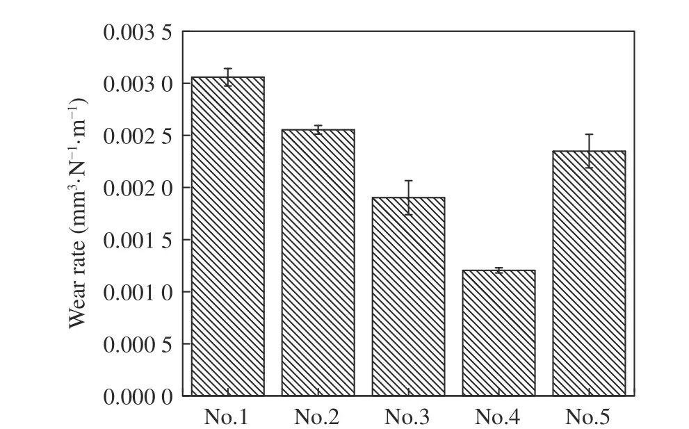
Fig. 9 The wear rate of tantalum coatings
3.4.4 Analysis of Coating Wear Mechanism
Based on the above analysis, the wear mecha−nism of plasma sprayed Ta coating can be sum−marized, and its schematic diagram is shown in Fig. 10. In the initial stage of wear, the particles on the coating surface are peeled off by the shearing force of the Si3N4ceramic balls, forming abrasive particles at the friction interface,scratching the coating and scooping out materi−als to form furrows. At this time, abrasive wear mainly occurs, and the Si3N4ceramic ball also suffers some wear. The contact area between the Si3N4ceramic ball and the coating gradually increases. The increase in the contact area causes a large amount of friction heat to accumulate during the friction process. The coating is par−tially softened and adheres to the surface of the Si3N4ceramic. At this time, a part of adhesive wear occurs at the friction interface. Due to the low density of the upper part of the coating,fatigue cracking occurs after the cyclic load exerted by the Si3N4ceramic balls, and a large number of cracks are generated at the friction interface, causing large pieces of coating material to fall off. Most of the fallen coating material and Si3N4ceramic debris are discharged from the fric−tion interface, and a small part is refined under the grinding action of the Si3N4ceramic balls and mixed with Si3N4ceramic debris to be embedded in the fallen pits and coating pores to make fric−tion the interface becomes smooth. Meanwhile,Si3N4has a certain degree of self−lubrication, so that the friction coefficient of the coating gradu−ally decreases and tends to be stable. When the coating has a higher density (sample No. 4), the friction interface does not have enough pores and pits to store the debris, causing the debris to form three−body abrasive particles at the friction interface, which will be scratched through the coating and scooped out the material forms a fur−row. And the wear form of the coating is mainly abrasive wear.
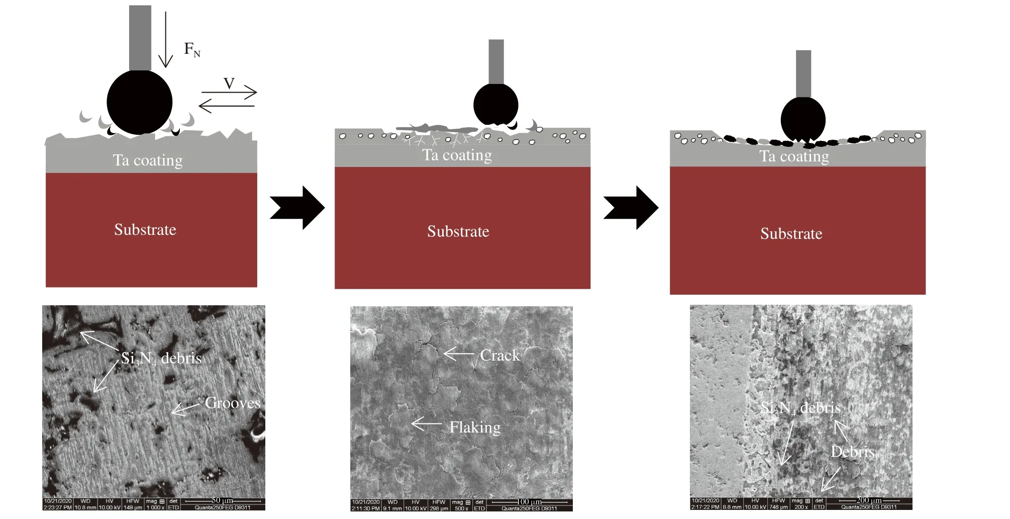
Fig. 10 The schematic diagram of wear mechanism of Ta coating
4 Conclusion
This paper mainly studied the tantalum coatings prepared by plasma spraying. The microscopic morphology, porosity and oxide layer changes of the tantalum coating during the preparation pro−cess were analyzed in detail. And through the analysis of the bonding strength and wear resis−tance of the coating, the influence of the auxil−iary airflow on the performance of the coating has been studied. The main conclusions are as follows.
1) The phase of plasma sprayed tantalum coating mainly contains Ta and Ta2O5.Ta2O5in the coating is distributed in bands. The oxida−tion degree of the coating first increases and then decreases with the increase of the auxiliary gas flow rate. When the auxiliary gas flow rate is 70 L·min-1, the degree of oxidation is the lightest.
2) The porosity and bonding strength of plasma sprayed tantalum coating are related to the oxidation degree of the powder during the spraying process. An appropriate auxiliary gas flow rate can reduce the oxidation of the coating.When the auxiliary gas flow rate is 70 L·min-1,the oxidation degree of the coating is the lowest,the porosity of the coating is the lowest at 0.21%,and the bonding strength is the highest at 59.3 MPa.
3) The wear resistance of plasma sprayed tantalum coating increases first and then decreases with the increase of the auxiliary gas flow rate. When the auxiliary gas flow rate is 70 L·min-1, the coating wear rate is 0.001 2 mm3·N-1·m-1, and the coating has the best wear resistance.
杂志排行
Journal of Beijing Institute of Technology的其它文章
- Application of Micro Electro Mechanical System(MEMS) Technology in Photoacoustic Imaging
- A New Class of Biodegradable Organic Optoelectronic Materials: α-Oligofurans
- Design of Implant Prosthesis for Bone Injury Repair Considering Stress Shielding Effect
- A Microfluidic System with Active Mixing for Improved Real-Time Isothermal Amplification
- Mixing Dynamics and Synthesis Performance of Staggered Herringbone Micromixer for Limit Size Lipid Nanoparticles
- Nanoscale Metal-Organic Frameworks:Stimulus-Response and Applications
