Design of Implant Prosthesis for Bone Injury Repair Considering Stress Shielding Effect
2022-06-30YixinShaoYeZhuTianminGuanQiHuBaozhongWeiBingLinLiyanZhangQianCao
Yixin Shao, Ye Zhu, Tianmin Guan, Qi Hu, Baozhong Wei,Bing Lin, Liyan Zhang, Qian Cao
Abstract: The failure of bone injury repair surgery is mostly due to the stress shielding effect caused by the difference of elastic modulus between the implant prosthesis and human bone, result−ing in a great damage to patients. To solve this problem, in this study, the influencing factors of the elastic modulus of implant prosthesis were investigated, the relationship between the elastic modulus of the implanted prosthesis and the influencing factors was analyzed, and then a design method of the implant prosthesis to reduce the stress shielding effect by adjusting the unit module to control the elastic modulus was established. This method was used for the biomechanical simula−tion to simulate the displacement and stress distribution between the implant prosthesis and the surrounding bone tissue, and then the reliability of the method was verified. The implant prosthe−sis with an elastic modulus consistent with that of the experimental dog bone was made by this method, and used for the animal experiments. The effects of implant prosthesis with different mod−ulus on the growth of surrounding bone tissue were observed, and at the same time, the reliability of the implant design method and the results of biomechanical simulation were verified. It is con−firmed that this method can effectively reduce the stress concentration of implant prosthesis by more than 15.4% and increase the growth of bone tissue by more than 21%.
Keywords: stress shielding; bone model; biomechanical simulation; gradient assignment
1 Introduction
Bone plays a vital role in the composition of human body [1]. Trauma, infection, tumor and abnormal development may cause bone defects,and the repair of bone defects is always one of the most urgent problems in the medical field.When the defect area of a bone is too large, its own ability to repair the bone tissue will not be enough, so it is necessary to implant a prosthesis to promote its healing and functional reconstruc−tion at this time [2]. However, in the process of repairing bone defects after the implantation of prostheses, stress shielding effect usually takes place. The main reason for it is that the elastic modulus of implant prostheses is higher than that of human bone, leading to a loose combina−tion between the implant prosthesis and human bone, and this “loose” will bring a great pain to patients. Even if the operation is successfully completed, many problems will still be encoun−tered in the subsequent rehabilitation treatment.In addition, some experimental data indicate that after the implantation of prostheses for repairing bone defects, the loosening of prostheses due to bone resorption accounts for about 70%, and the pathological fracture rate of bone tissue around the prosthesis is four times that of prosthesis itself, which is likely due to the stress shielding effect.
In recent years, 3D printing technology has been favored by the medical field. Relevant scholars [3−8] believe that the porous structure implant prosthesis prepared by 3D printing tech−nology has shown some advantages over the tra−ditional implant prosthesis in controlling elastic modulus, shape matching, improving degradabil−ity and biocompatibility, with a good fatigue resistance, corrosion resistance, wear resistance,and a good compatibility. As Plyusnin [9] said,implanting a prosthesis should be easy to oper−ate during operation, but the prosthesis itself is important, that is, first, there is no migration of the prosthesis during the healing process of bones; secondly, it should have a good biocom−patibility and can promote the healing of bones,with a bone conductivity, bone induction, osteo−genesis and/or bone promotion at the same time;finally, the material should be strong and hard enough for clinical application from the mechan−ics of materials, which should reduce the risk of complications, especially those associated with the surgical site infection, thereby reducing the need for revision surgery and the associated risks.3D printing porous implant prosthesis has been widely regarded by scholars. Sargeant et al. [10]reported that the Ti−6Al−4V foam with a poros−ity of 52.5% would form a bioconductive mixture and make the tissue cells wrap around it.Warnke et al. [11] found that the bone tissue would begin to grow into the implant prosthesis with a pore about 200 μm about 12 weeks after implantation. Barbas et al. [12] confirmed by finite element simulation and mechanical experi−ments that a porous structure implant prosthesis with an unit size of 0.9 mm× 0.86 mm × 1.5 mm and a porosity of 53% was beneficial as a bone graft substitute. It was found by Li et al. [13]that in the co−culture of 300-400 μm, 400-500 μm and 500 -700 μm porous titanium alloy(Ti-6Al-4V) scaffolds processed by 3D printing with bone marrow mesenchymal stem cells, the 300−400 μm scaffold showed the best perfor−mance in the proliferation and osteogenic differ−entiation of bone marrow mesenchymal stem cells, and an obvious bone growth into the 300-400 μm scaffold was also observed after it was implanted into goats. Kausik et al. [14]believed that the implant prosthesis with a porosity of 75.4% and an average pore diameter of 178 μm had a significant osteogenic effect on human bone marrow mesenchymal stem cells. In recent two years, more and more scholars have devoted themselves to the research on porous implant prosthesis scaffold materials [15−20].
The majority of scholars have carried out a lot of research on eliminating the stress shielding effect after the implantation of prostheses for repairing the bone injury. However, most of them focus on the properties of materials and the porosity of porous structure, and there are few reports on the mapping relationship between the mechanical properties or elastic modulus and the structural parameters of implant prosthesis. The main contents of this study included ① the establishment of the mapping relationship between the modulus of implant prosthesis and its structure, ② the biomechanical simulation and analysis of implant prosthesis and its sur−rounding bone tissue, and ③ the analysis on the effects of implant prosthesis with different modu−lus on the growth of surrounding bone tissue, and the verification of the reliability of implant pros−thesis design method and the results of biome−chanical simulation through in vivo implantation experiments in animals. This study was expected to provide not only an experimental support for eliminating the stress shielding effect in the repairing process of bone defects after implant prosthesis, but also experimental data for rele−vant biomechanical studies. The research proto−col is shown in Fig. 1.
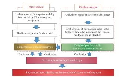
Fig. 1 Protocol
2 Materials and Methods
2.1 Design of Controllable Elastic Modulus Implant
2.1.1 Analysis of Stress Shielding Causes
Osteoblasts and osteoclasts in bone tissue can regulate the growth or absorption of bone tissue through baroreceptors. When the implanted pros−thesis is stressed together with the surrounding bones, an excessive stress is concentrated on the implant prosthesis. The reason is that the elastic modulus of the implant prosthesis is generally higher than that of human bones and then less stress is concentrated on the surrounding bones of the implant prosthesis, with a stress shielding effect, resulting in a loss of bone mass or a poor development of bone structure, which may cause a delayed healing and even pathological frac−tures of the bones after operation. Therefore,controlling the degree of stress shielding or elimi−nating the effect of stress shielding is the key to improve the success of implant prosthesis in repairing bone defects. The degree of stress shielding can be expressed by the stress shielding rateηas


whereηis the stress shielding rate;σ0is the stress on the bone when the prosthesis is not implanted;σis the stress on the bone after the implant prosthesis;Eis the elastic modulus;εis strain. The greater the stress shielding rateη, the more serious the stress shielding will be, and the elastic modulus of human bones varies from per−son to person, with significant differences. There−fore, it is possible to completely eliminate the stress shielding effect only by a personalized cus−tomization to make the elastic modulus of implanted prosthesis consistent with that of human bones.
2.1.2 Analysis of Influencing Factors of Elastic Modulus of Implant Prosthesis
The calculation formula of elastic modulus is

whereEis Yang’s modulus;Fis the external load;Ais the cross−sectional area;Lis the origi−nal length of the material; ΔLis the deformation displacement.
The implant prosthesis in this study is a porous structure. It can be seen from the analy−sis of comprehensive Eq. (3) and the composi−tion conditions of porous structure that there are many factors affecting the elastic modulus of an implant prosthesis with porous structure, of which the major factors are the constitutive model of implant prosthesis with porous struc−ture, and the natural elastic modulus and pois−son’s ratio of materials used for fabrication of implants.
According to Eq. (3), our team had com−pleted the preparation of finite element simula−tion script [21] designed with reference to “Metal−lic materials−compression test methods at room temperature” GB/T 7314-2017. The model estab−lished according to the script was verified by finite element simulation and real mechanical experiments, with a high reliability. The script was considered to be suitable for the finite ele−ment simulation of diamond structure modulus.Diamond structure (Fig. 2(a)) can be regarded as a tetrahedral structure, and the tetrahedral structure generally has a stronger stability com−pared with other spatial structure. It took advan−tage of the good stability of diamond structure to select it as the unit structure of implant prosthe−sis with porous structure in this study. Accord−ing to the structural unit characteristics of dia−mond structure, a structural unit model with controllable structural parameters was estab−lished (Fig. 2(b)). The model could be filled into the prosthesis model by repeated superposition(Fig. 2(c)), convenient for the biomechanical calculation and processing of implant prosthesis for animal experiments. The trend of elastic mod−ulus of implant prosthesis filled with this model with the change of structural unit size and poros−ity had been analyzed in previous studies. In order to further analyze the factors and weights affecting the modulus of implant prosthesis with a porous structure, the control variable method was used to modify the side length of structural element, the radius of support rod, the elastic modulus of inherent material and Poisson’s ratio respectively to conduct mechanical simulation,and the results were fitted into a function for−mula.
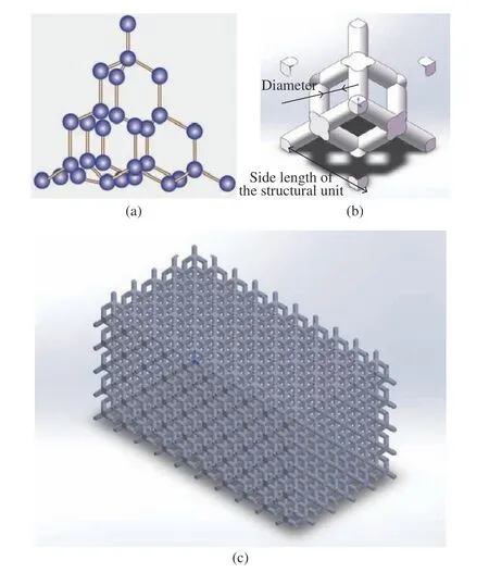
Fig. 2 Diamond structure: (a) micro structure; (b) structural element; (c) porous structure
In this experiment, the side length of the structural element was set as the variable in experimental group A, the radius of the support rod was set as the variable in experimental group B, the elastic modulus of the inherent material was set as the variable in experimental group C,and the Poisson’s ratio of the inherent material was set as the variable in experimental group D.The simulation was carried out with the running script of the finite element numerical simulation software and the curve was drawn, and the curve was fitted into a function formula.
2.2 Calculation and Analysis of Implant Prosthesis in Biomechanics
2.2.1 Model Establishment
The experimental dog was scanned by CT using ScintCare CT16X−ray computed tomography equipment. The thickness of the scanning layer was 1 mm, and the scanned image file was saved as DICOM3.0 format. Mimics19.0 software is used to process the CT images obtained by scan−ning. The software can perform fast segmenta−tion of CT images based on thresholds (Fig. 3(a)).The extracted model (Fig. 3(b)) was rough and there were many redundant fragments in it, and its surface was not so smooth, which could affect the finite element mesh generation and static analysis, so the model could not be used for the subsequent finite element analysis. Hence, Geo−magic wrap2017 software was used for the pro−cessing and optimization to delete the irrelevant fragments and bottom plates, and the processed model became relatively clear (Fig. 3(c)). The bones of the limbs of the experimental model dog were numbered, as shown in Fig. 3 (c).
2.2.2 Gradient Assignment of Material Proper−ties
The optimized model was reconstructed to gener−ate a solid surface, and HyperMesh software was used for meshing (Fig. 4(a)), and the data of mesh quality inspection are shown in Fig. 4(d).The material properties of the divided model were assigned. Studies have shown that there is a linear relationship between the bone elastic mod−ulus and the bone gray value [22]. In this paper,the elastic modulus of the bones of the limbs was obtained by using Mimics software combined with the calculation of the bone ash value. The calculation methods are as follows.
Poisson’s ratio assignment:

Density assignment when the gray value is 101 and less than 101:

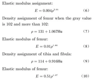
whereρis the apparent density in the image obtained by CT scanning (g/cm3) ; Hu is the gray value of bones;Eis the elastic modulus of the main research bones (MPa).
The elastic modulus of the bones of the limbs of the experimental model dog could be calculated according to the above formulas. In combination with the function of material assign−ment by Minics software, the bone model of the experimental dog could be assigned by using 10 gradient assignment methods with different me−chanical properties. Taking LF1 as an example,the 3D model of the experimental dog bone is shown in Fig. 4(b), and the model established by this method is shown in Fig. 4(c). The results showed that the mechanical properties of the ma−terial were closer to those of the actual bone tis−sue.
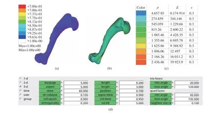
Fig. 4 Assignment of material properties of the bones: (a) mesh generation; (b) assignment effects; (c) material properties; (d) data for mesh quality checks
2.2.3 Biomechanical Simulation
Biomechanical simulation can be used to analyze the stress distribution under the joint load of implant prosthesis and surrounding bones. The data can not only predict the results of animal experiments, but also verify the relia−bility of implanted prosthesis model. In this experiment, the effect of implant prostheses with different modulus on the stress and displacement of surrounding bone tissues was simulated by a simulated mechanical experiment, and the results were analyzed. The model with a projection area of 1 cm2on the 3D bone model of experimental dog with gradient assignment was intercepted and set as the implant prosthesis model, and the average elastic modulus of the experimental dog bones calculated in combination with the gray value and the modulus of the implanted prosthe−ses in the experimental design are shown in Tab.1. An experimental group and a control groupwere designed, and the elastic modulus of bones was set. The control group was divided into two categories, control group A (the modulus of implanted prosthesis was greater than the aver−age modulus of bones in experimental dog) and control group B (the modulus of implanted pros−thesis was less than the average modulus of bones in experimental dog).
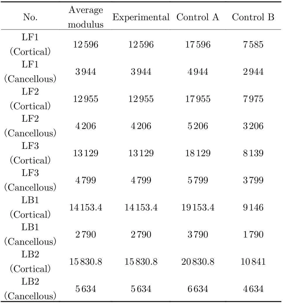
Tab. 1 Assignment of material properties for the experimental group vs control group MPa
The stress distribution and displacement of implant prosthesis and its surrounding bones were simulated by applying a load. The degrees of freedom in six directions of the lower end face of the main bones each were constrained. In applying the loads, the upper surface of each main research bone was coupled to one point,respectively, and a vertical downward axial load was applied. Since the weight of the experimen−tal dog was 10 kg and its two feet were always on the ground during the movement, with a cer−tain impact force, the applied axial load was 70 N (Fig. 5). The displacement changes and stress distribution in the experimental group and the control group were compared and analyzed. The stress on the implant prosthesis with an applied load was obtained by randomly taking 10 points to calculate their average value.
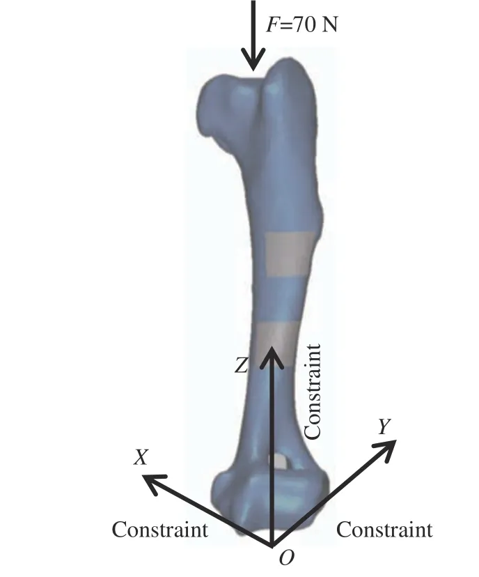
Fig. 5 Loading method
2.3 Animal Implantation Experiments
2.3.1 Experimental Objectives
The reliability of the controllable elastic modu−lus implant model designed in this study was ver−ified through the experiment of repairing bone defects by implant prostheses in a dog. If the bone tissue growth of the experimental group designed with implants in this study is better than that of the control group, it indicates that the implants designed in this study have better reliability; otherwise, it indicates that the implants designed in this study do not effec−tively weaken the stress shielding effect. In addi−tion, the results of biomechanical simulation analysis were examined. If the experimental results were consistent with those of biomechani−cal simulation analysis, it was considered that the model design method used in the biomechani−cal simulation analysis should be consistent with the actual situation and could be applied in the subsequent experiments. Furthermore, this exper−iment could be also used to analyze the growth law of bone tissue around implant prostheses with different elastic modulus, so as to provide an experimental support for the relevant biome−chanical research, and also a preliminary research basis for the follow−up experiment of human bone defect repair.
2.3.2 Experimental Objects and Instruments
In order to obtain a complete and real bone model of animal research object, the experimen−tal object in this study was a healthy beagle dog aged one year old.
The main experimental instruments used in this study: Laser molten metal rapid prototyping machine AM250 (Renishaw Company, UK);ScintCare CT16X−ray computed tomography equipment (Zhejiang Mingfeng Medical System Co., Ltd., China); Skymen JP−020S ultrasonic cleaning machine (Guangdong Tianmen cleaning equipment Shenzhen Co., Ltd., China); RayNova DRsc4 digital photography X−ray machine(Liaoning Cape Medical System Co., Ltd.,China); Medical image control system Mimics 19.0 (Materialise, Belgium). Some equipments are shown in Fig. 6.
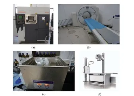
Fig. 6 Experimental instruments: (a) AM250; (b) ScintCare CT16X; (c) Skymen JP−020S; (d) RayNova DRsc4S
2.3.3 Experimental Procedures
1) Design of implant prosthesis model:according to the elastic modulus values shown in Tab. 1, an implant prosthesis that met the bone modulus of the limbs of the experimental dog were processed. The model with a projection area of 1 cm2from the bone model of the limbs of the experimental dog was intercepted as the model of the implant prosthesis, and the porous structure was treated. The specific parameters of the unit structure of the porous structure were calculated based on the mapping relationship between the elastic modulus of the implant prosthesis and its own structure, and the optimized 3D printing parameters were used for the processing of tita−nium alloy. According to the previous study [21],the elastic modulus of the material was con−trolled to 31.51 GPa and the Poisson’s ratio was 0.144. On this basis, the structural parameters of the implanted prosthesis unit could be obtained by using the functional relationship between the side length of the structural unit, the radius of the support rod and the elastic modulus of the implanted prosthesis, and the implanted prosthe−sis was designed based on these parameters. Tak−ing LF1 as an example, the 3D model of the imp−lanted prosthesis is shown in Fig. 7(a) and (b).
2) Test−piece preparation: a laser molten metal rapid prototyping machine AM250 was used for the fabrication of implant prosthesis.The fabricated implant prosthesis was subjected to heat treatment and ultrasonic cleaning, and the specific procedures were as described in the previous study [21]. In order to facilitate the implant operation, the limb bone model of the experimental dog with the implanted prosthesis removed was processed with a resin printer. Tak−ing LF1 as an example, the implanted prosthesis and bone model are shown in Fig. 7.
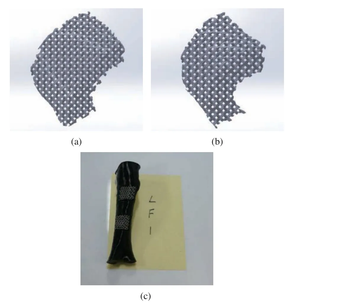
Fig. 7 Model of implanted prosthesis: (a) implanted prosthe−sis above of LF1; (b) implanted prosthesis below of LF1; (c) bone model
3) Animal experiment: The experimental dog was raised in an air−conditioned room, under the normal work and rest conditions, and with a commercial dog food and free access to drink fresh water before and after operation. The implant prosthesis was implanted into the dog in 8 operations, and the operations were carried out in Animal Laboratory, Beihua University (Jilin,China). All animal experiments complied with the ARRIVE Guidelines and followed the U.K.Animals ( Scientific Procedures) Act 1986 and associated guidelines, and EU Directive 2010/63/EU for Animal Experiments. This study was approved by the Beihua University Medical Ethics Review Committee. The informed consent was obtained in writing from all the individual participants included in the study. During the operation, the general anesthesia, standard asep−tic conditions and analgesic procedures were applied. A small surgical incision of about 2 cm was made at the corresponding position of the leg bone model gap. Then, the subcutaneous tissue and periosteum were bluntly separated to expose the bone surface, and the gap consistent with the size of the implanted prosthesis was prepared with a pendulum saw and washed with normal saline (0.9%). The sterilized implanted prosthe−sis was insert into the gap (Fig. 8(a) and (b)),and the periosteum, subcutaneous tissue and skin were sutured layer by layer and the wound was washed with iodophor and normal saline (Fig.8(c)). The dog was awakened by intravenously injecting atimidazole hydrochloride after opera−tion, and intravenously given clindamycin phos−phate during the first three days for antibacte−rial treatment. The results showed that the experimental dog showed no infection symptom(Fig. 8(d)). The clinical observation indexes included the postoperative activity, the daily diet and the incision healing of experimental dog. At 1, 3, 7 and 34 weeks after operation, the dog’bones around the implanted prosthesis were examined by X−ray photography and CT scan−ning under general anesthesia. The X−ray photog−raphy process is shown in Fig. 8(e), the CT scan−ning in Fig. 8(f), the X−ray photography results in Fig. 8(g), and the CT photography results in Fig. 8(h). Ten points at the position connected with each implanted prosthesis on the bone model obtained by each CT scanning were ran−domly selected to obtain the gray value of each point. The average value was calculated for the comparative analysis. The experimental dog was euthanized at the 34th week after the implanta−tion of prosthesis.
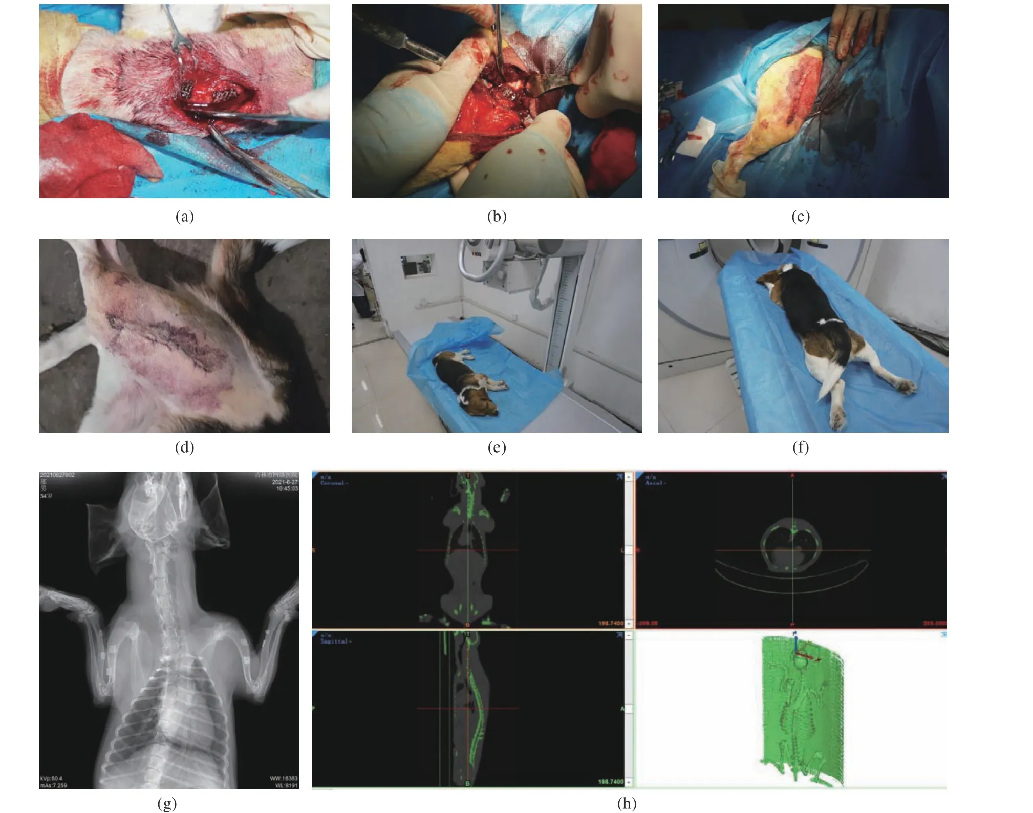
Fig. 8 Animal experiment: (a,b) process of implanting a prosthesis; (c) wound after surgery; (d) no infection developed after surgery;(e) X−ray photography; (f) CT scanning; (g) X−ray photography results; (h) CT photography results
3 Experimental results
3.1 Design of Implant Prosthesis with Controllable Elastic Modulus
The mechanical simulation was carried out with ANSYS software to simulate the influence of modifying the side length of structural unit, the radius of support rod, the modulus elasticity of inherent material and the Poisson’s ratio on the material modulus of porous structure. The simu−lation result curves were drawn. The curve of the side length of structural unit versus the material modulus is shown in Fig. 9(a), that of the radius of support rod versus the material modulus in Fig. 9(b), that of the modulus elasticity of inher−ent material versus the material modulus in Fig.9(c) and that of the Poisson’s ratio versus the material modulus in Fig. 9(d), respectively. It could be understood that the modulus of porous structural materials decreased with the increase of the side length of the structural unit, increased with the increase of the radius of the support rod, directly proportional to the elastic modulus of the inherent material, and decreased with the increase of the Poisson’s ratio of the inherent material. The function formula of fitting four curves is shown in Fig. 9, in which the curve in Fig. 9(a) is a function of order 9, that in Fig.9(b) is a function of order 6, that in Fig. 9(c) is a positive proportional function, and that in Fig.9(d) is a function of order.
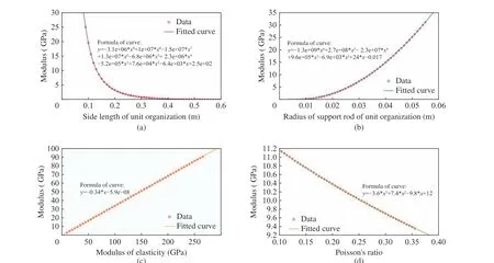
Fig. 9 Results of ANSYS simulation: (a) curve of the side length of structural unit versus the material modulus; (b) curve of the radius of support rod versus the material modulus; (c) curve of the modulus elasticity of inherent material versus the material modulus; (d) curve of the Poisson's ratio versus the material modulus
3.2 Biomechanical Simulation Analysis
Through the gradient assignment of the experi−mental dog bone model and the differential mod−ulus assignment of the implanted prosthesis,under the condition of applying load, the mechanical simulation around the implanted prosthesis during the walking of the experimen−tal dog, and the possibility of displacement between the implanted prosthesis and its sur−rounding bone tissue and the change of stress dis−tribution due to the different modulus of the implanted prosthesis were analyzed (Tab. 2).Taking the displacement change and stress distri−bution of LF2 bone as an example, it could be seen that the implant prosthesis with different elastic modulus had a certain impact on the dis−placement change between the implanted pros−thesis model and the bone model after loading.There was no way to determine the location of the maximum stress by observing the color. How−ever, it could be seen that the implanted prosthe−sis with different elastic modulus should have a certain impact on the stress distribution after loading. The stress was more concentrated on the implanted prosthesis model in control group A,while the stress was less concentrated on the implanted prosthesis model, but more stress was concentrated on the bone model near the implanted prosthesis model. The effect was much more significant than that of the elastic modulus of the implanted prosthesis in control group B.The mechanical simulation experiment of stress distribution indicated that due to the deforma−tion of the shape of the surrounding bones caused by the defect, the stress shielding effect could notbe completely eliminated even if the elastic mod−ulus of the implanted prosthesis was adjusted to be consistent with that of the surrounding bones,and the maximum stress concentration point of the implanted prosthesis would appear at the side edge perpendicular to the stress direction when the elastic modulus of the implanted pros−thesis was higher than that of the surrounding bones. These two results were different from those predicted previously [21]. However, it was undeniable that the stress concentration was not so significant when the elastic modulus of the implant prosthesis was consistent with that of the surrounding bones. It was observed that the stress concentration in the control group A was about 15.4% higher than that in the experimen−tal group when the elastic modulus of the implant prosthesis was higher than that of the surrounding bones by 5 GPa, indicating that the design method in this paper can effectively reduce the stress shielding effect.
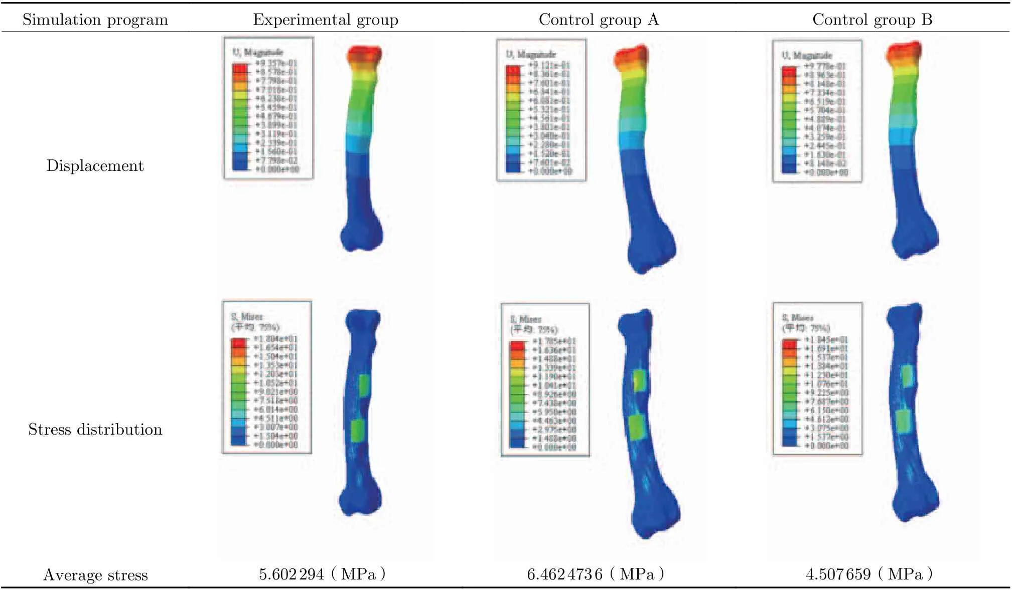
Tab. 2 Changes of displacement and stress distribution of bone LF2
3.3 In Vivo Implantation Experiment
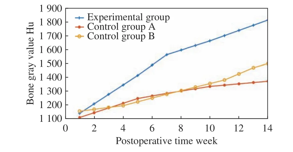
Fig. 10 Results of animal experiments
The experimental dog was well tolerated after the implantation of prostheses, and no inflamma−tion, soft tissue suppuration or infection in all the wounds after operation. At the 34th week after operation, there was no implant loss, and no fail−ure or displacement of the implanted prosthesis,with a success rate of 100%. The curve of the average gray value of the bone tissue around the implanted prosthesis was drawn in the experi−mental group and the control group, respectively.As shown in Fig. 10, the gray value of the bone tissue around the implant prosthesis increased in an upward trend with the prolongation of postop−erative time in the experimental group, while the gray value of the bone tissue around the implant prosthesis increased slowly and the saturation state appeared in the later stage although it also increased with the prolongation of postoperative time in the control group A. In the control group B, the gray value of bone tissue around the implant prosthesis showed a slow growth trend with a prolongation of postoperative time, and the growth rate was far lower than that in the experimental group although there was no satu−ration state in the later stage.
4 Discussion
The causes of stress shielding effect in the pro−cess of repairing bone injury with implanted prosthesis were analyzed in this study, namely,the elastic modulus of implanted prosthesis higher than that of human bone could result in a too excessive stress concentration on implanted prosthesis. In view of this problem, the influenc−ing factors of the elastic modulus of implant prosthesis were investigated, and then an implant prosthesis model with controllable elastic modu−lus was designed. A way of controlling the elas−tic modulus of implant prosthesis by adjusting the unit module was proposed and a design method of implant prosthesis was established to reduce the stress shielding effect. The mechani−cal simulation experiments were carried out by using this method combined with the biomechan−ical model with gradient assignment. Finally, the growth law of bone tissue around the implant prosthesis with different elastic modulus was obtained by animal experiments, and the reliabil−ity of the design method of controllable elastic modulus implant prosthesis was verified at the same time.
Previously, Ting Liu et al. [8] reported that the porous structure significantly reduced the elastic modulus of Ti-6Al-4V alloy, but had no substantial effect on the compressive strength of Ti-6Al-4V alloy. Lai et al. [23] established com−mon regular porous structures by summarizing the structure of 3D printing implant prosthesis,such as cubic structure, diamond structure and rhombic dodecahedral structure, with elastic modulus in the range of 0.5 -15, 1.3 -1.9 and 0.5-6.5 GPa. On this basis, the influencing fac−tors of the overall modulus of diamond porous structure and their influencing degrees were explored in this study. Then the functional rela−tionship between the modulus and the influenc−ing factors was fitted, and an implant prosthesis model with controllable elastic modulus was designed. The model was considered to more effectively slow down the stress shielding effect than the porous structure designed by Lai et al.
The way of obtaining personalized bone model by CT scanning in this study was some−what similar to that of the personalized implant prosthesis designed by Ye Ziheng [24] and Song Changhui [25], but not only the gradient assign−ment for the obtained personalized model was performed, but also the elastic modulus of implant prosthesis was designed individually in this study. Although Kang Jianfeng et al. [26]also established a variable modulus microstruc−ture design, the research remained at the micro level and the biomechanical simulation with bone model was not carried out. In this study, the stress concentration could be effectively reduced by more than 15.4% by controlling the elastic modulus of the implanted prosthesis to make it consistent with that of the surrounding bone tis−sue.
Ting Liu et al. [8] also carried out in vivo implantation experiments in animals and their results showed that the number of new bone cells formed around the porous implant prosthesis increased, and the cells grew deep into the pores from the second week to the eighth week. The growth of bone tissue around the porous implant prosthesis with different elastic modulus was observed in this study. Furthermore, it was con−firmed that the growth of surrounding bone tis−sue could be improved by more than 21% and the experimental cycle was also prolonged by the design method of implant prosthesis, so that it was observed that the implant with a high elas−tic modulus could make the surrounding bone tis−sue in a saturation state on the 10thweek after operation. The bone tissue growth was compared after the implantation of prosthesis in the same experimental dog in this experiment, which could better eliminate the experimental errors caused by individual differences, and the comparison results might be more accurate. However, it is undeniable that there is a certain degree of par−ticularity in the in vivo implantation experiment of only one experimental dog, so the possibility of the individual particularity of the experimental dog cannot be ruled out, which will be further discussed in the follow−up studies.
In conclusion, the implant prosthesis designed in this study could control the change of its elastic modulus to meet the needs of human individual differences more, and the reliability of this design method can be verified by biomechan−ical simulation and in vivo implantation in ani−mals. The application of this design method can effectively reduce the stress shielding effect, and the method may provide a great help for patients with bone injuries, with a good application prospect in the future.
5 Conclusions
In view of the problem that the stress shielding effect would affect the effect of prosthesis repair surgery, a porous structure implant prosthesis with variable elastic modulus was designed by summarizing the mapping relationship between the tissue structure of porous structure unit and the elastic modulus of the model. In vivo animal implantation experiments in animals were car−ried out by using a three−dimensional model with gradient assignment.
The influencing factors and corresponding influence degrees of the overall modulus of the porous structure of the implant prosthesis were analyzed. A large number of mechanical simula−tion data were used to draw a change curve of the modulus of the implant prosthesis and the functional relationship with the corresponding influencing factors was fitted. The formula could be used to calculate the modulus of the porous implant prosthesis, and then an implant prosthe−sis model with variable elastic modulus was designed.
A three−dimensional model more in line with the real situation of bone was established by using CT scanning and gradient assignment. The displacement and stress distribution of the implant prosthesis and surrounding bone tissue after prosthesis implantation in vivo were stud−ied by using this model. The biomechanical model was verified by animal implantation exper−iments, confirming that the gradient assignment method of the model can be applied to the estab−lishment of mechanical simulation model for this kind of research.
It was proved that the consistence of the elastic modulus of implant prosthesis with that of the surrounding bone tissue could effectively reduce the stress shielding effect, with a decrease of the stress concentration by more than 15% in this study. This conclusion should be helpful to establish the research direction of postoperative stress shielding effect, and may provide a help for the future research of personalized modulus implant prosthesis and the elimination of postop−erative stress shielding effect.
The implant prosthesis processed by the implant prosthesis design method in this study is more conducive to the growth of the surround−ing bone tissue in the animal implantation exper−iment, with an increase in the bone tissue growth by more than 21%. In a way of long−term postop−erative rehabilitation and multiple CT scans, the influence law of the mechanical properties of the implant on the growth of the surrounding bone tissue is summarized, which can be applied to the research of the repair of bone injury with related implant prostheses.
杂志排行
Journal of Beijing Institute of Technology的其它文章
- Application of Micro Electro Mechanical System(MEMS) Technology in Photoacoustic Imaging
- A New Class of Biodegradable Organic Optoelectronic Materials: α-Oligofurans
- A Microfluidic System with Active Mixing for Improved Real-Time Isothermal Amplification
- Mixing Dynamics and Synthesis Performance of Staggered Herringbone Micromixer for Limit Size Lipid Nanoparticles
- Effect of Auxiliary Gas Flow Parameters on Microstructure and Properties of Ta Coatings Prepared by Three-Cathode Atmosphere Plasma Spraying
- Nanoscale Metal-Organic Frameworks:Stimulus-Response and Applications
