Key Construction Technology of Ultra-deep Diaphragm Wall Under Complicated Geological Conditions*
2022-06-21SHIJiangchuanLIUWeiweiCHENGPeichunNIEYanxiaZHUHaoboXIEZhicheng
SHI Jiangchuan, LIU Weiwei, CHENG Peichun, NIE Yanxia, ZHU Haobo, XIE Zhicheng
(1.China Construction First Group Construction & Development Co., Ltd.,Beijing 100102,China;2.Installation Engineering Co., Ltd. of First Bureau Group of CSCEC,Beijing 102600, China)
Abstract: The LNG Receiving Station project in Shenzhen is located in a land reclamation area with complicated geological conditions. The thickness of diaphragm wall is 1.5m, the depth is up to 62m, and is extremely difficult to construct. During the construction process, slot wall reinforcement technology is used to ensure the stability of slot formation, and milling-drilling-milling technology is used to address the problem of ultra-deep rock of diaphragm wall. The super-large reinforcement cage of underground continuous wall is built and lifted in one time to ensure the construction quality and safety, and the green construction is achieved by adopting the green and environment-friendly mud circulation treatment technology. The construction technology of ultra-deep diaphragm wall applied in the project yielded positive results and has the potential be become more widely used.
Keywords:underground engineering;diaphragm wall; reinforcement cage;mud circulation; construction
0 Introduction
The LNG Receiving Station project in Shenzhen is an important component of the second line of the west-east natural gas transportation project. Its functions including emergency response, peak regulation and natural gas supply to Guangdong and Hong Kong, China. The first phase of the project will involve the construction of two LNG storage tanks of 200,000m3. The project will play an important role in guaranteeing the natural gas supply in the Pearl River Delta and Hong Kong, China, which is strategically significant. The project is located in a sea reclamation area, with the ocean on the other deep and newly filled soil is under the surface, and the underlying bedrock is strong and thick. On the whole, it is soft at the top and hard at the bottom.
1 Overview of the project
1.1 Overview of diaphragm wall
In the project, circular foundation excavations T-1201 and T-1202 with an inner diameter of 100m and a design depth of 50m are set up. The foundation excavation bottom is located in medium and breezed rock strata, and the underground continuous wall and inner wall are adopted to form overlapping external walls. The thickness of underground diaphragm wall is 1.5m, and the grooves can be classified by two types. Using a width of 2.8m, the type Ⅱ groove is slotted with a knife. The sleeve milling joint is used between the type Ⅰ and type Ⅱ grooves, as shown in Fig.1. Each foundation excavation is surrounded by 72 underground continuous walls, the depth of which is 54~62m, and the perpendicularity of which must be 1/600.

Fig. 1 Trench type of diaphragm wall
1.2 Geological conditions
The project site was originally a sea area, which was subsequently reclaimed. From top to bottom, the strata are mainly composed of Quaternary Holocene artificial filling layer, continental inter-sedimentary layer, alluvial diluvial layer, Quaternary weathering residual layer, and the underlying bedrock is Cretaceous granite, conglomerate, quartz porphyry and quartz sandstone.
The thickness of artificial soil filling in the upper section of the site is about 6.2~13.77m, and the self-weight consolidation has not been completed yet, resulting in inadequate stability. The underlying bedrock varies obviously from east to west, which contain granite, quartz porphyry and conglomerate in turn, as shown in Fig.2. According to the geological survey report, the bedrock strength of this project is extremely high. The compressive strength of granite is 60.54MPa on average and 89.90MPa at the maximum. The average compressive strength of quartz porphyry is 52.36MPa, with a maximum of 61.10MPa. The average compressive strength of conglomerate is 46.46MPa, with a maximum of 63.30MPa. The average compressive strength of quartz sandstone is 84.35MPa, with the maximum of 90.30MPa.
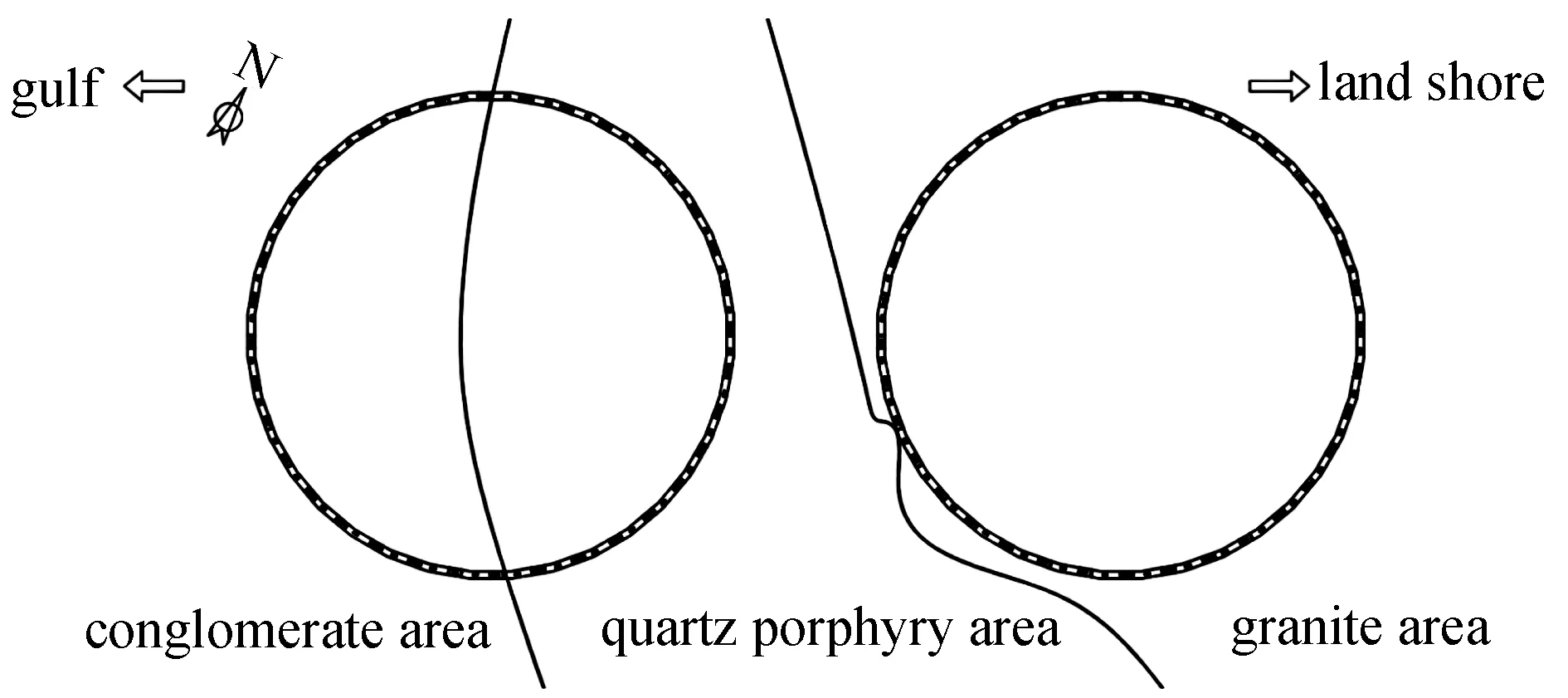
Fig. 2 Rock stratum distribution plan
Ground water mainly consists of upper stagnant water, pore confined water and bedrock fissure water. The upper stagnant water is mostly supplied by atmospheric precipitation and seawater infiltration, and the buried depth of the stable water level is 1.80~2.80m. The pore confined water is mainly supplied by atmospheric precipitation and seawater infiltration, and the buried depth of stable water level is -1.43~6.40m. Bedrock fissure water is mainly supplied by lateral drainage, and the buried depth of stable water level is 12.10~24.00m.
2 The challenges of the project
1) The project site is produced via land reclamation and is located in a coastal area, with abundant groundwater, and the site is formed by. The backfilling time of the upper soil is limited, and the gravity consolidation has not yet been completed. The stability of the soil is very weak. In this project, the underground diaphragm wall is a permanent structure, which requires high quality of wall construction. Therefore, it is critical to make reasonable plans and take effective methods to manage the forming quality of the underground diaphragm wall.
2) The bedrock strength of the site is quite strong, making conventional construction methods impossible to groove smoothly. The rock undulation is severe, and the depth of an underground continuous wall into the rock can be as high as 20~30m, with a perpendicularity of 1/600. Therefore, the key to the success or failure of construction is to select the suitable slot-forming method and controlling verticality.
3) The steel cage in this project is too lengthy and the reinforcement is dense, making it difficult to construct and lift. Appropriate construction methods should be adopted to reduce the deformation of the steel cage and control the safety of the lifting of the steel cage.
4) The construction volume of ground wall is enormous, and the volume of single slot section is large. The mud consumption is high, and it is located near a beach and tourism region. Then the environmental protection requirements must be in a high level. The orderly operation of mud treatment system should be considered to ensure the mud supply capacity and meet the requirements of green construction.
3 Project analysis of key construction technology
3.1 Groove wall stability reinforcement technology
According to the stratum distribution, the thickness of the artificial filled soil is more than 10m, and there are adverse geological conditions such as silt below the filled soil. The site is surrounded by the sea, with a high groundwater level and a replenishment quantity. The deepest trough formation depth of the underground continuous wall reaches 62m, and the possibility of trough instability is substantial. To ensure the stability of the diaphragm wall during the construction process, the wall is reinforced with a three-axis cement soil mixing pile before it is formed.
In the slotting range, six rows ofφ850mm triaxial mixing piles are arranged, as shown in Fig.3. The depth of mixing piles is about 18~30m, ranging from the ground to the top of the whole weathering layer. The cement percentage of soil-cement mixing piles is no less than 20%. The middle four rows of mixing piles are mainly located in the groove, and neighboring rows and piles are overlapped 250mm. The outer two rows of mixing piles adopt the method of drilling a hole, and the lap connection between piles is relatively full. In addition to reinforcement, the piles offer good water stopping performance, and serve as a water stopping curtain.
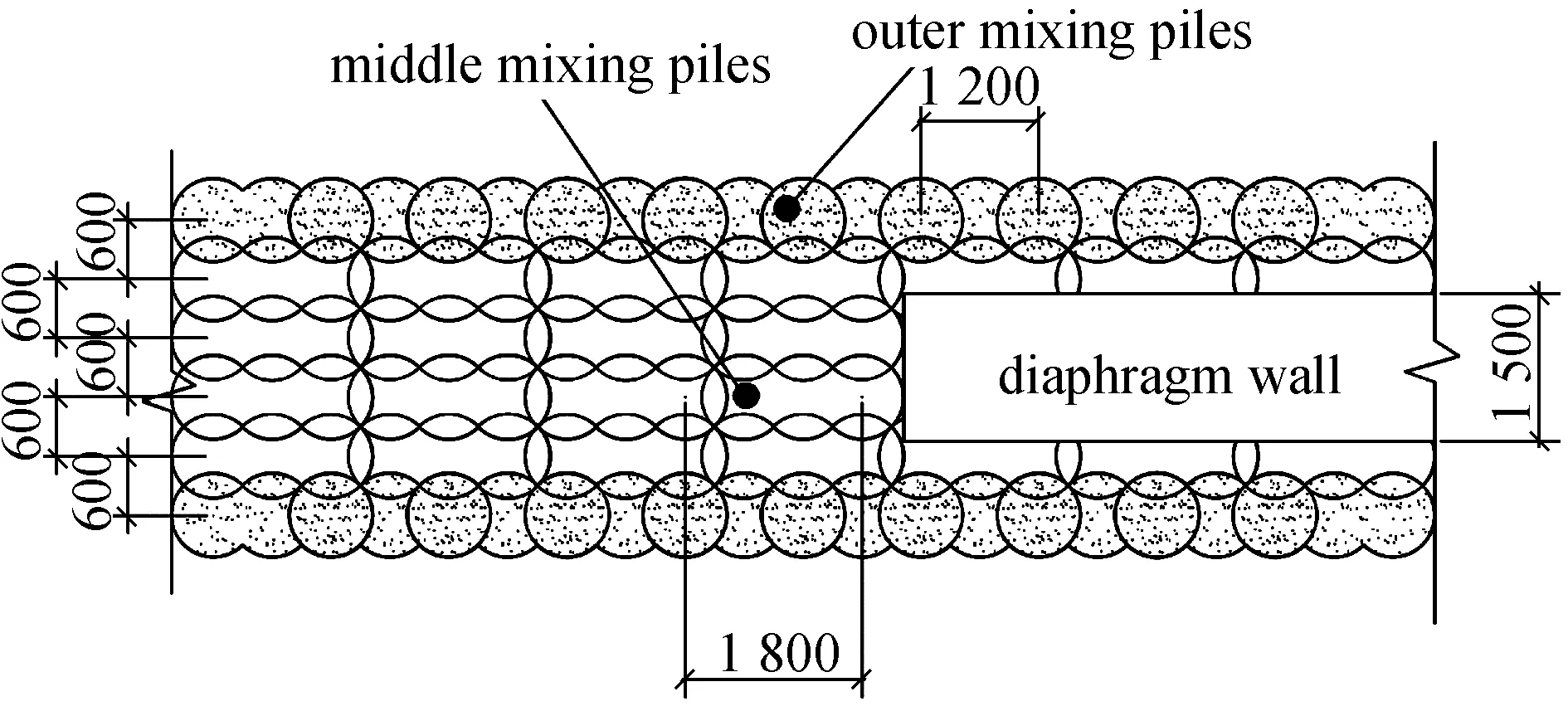
Fig. 3 Schematic diagram of three-axis mixing pile reinforcement
After the cement-soil mixing pile construction is completed, the strength of cement-soil test block is evaluated by drilling core method. According to the test results, the 28d unconfined compressive strength of soil-cement is more than 0.8MPa, which meets the design requirements and the requirements of underground diaphragm wall slotting.
3.2 Trough formation technology of ultra-deep rock underground continuous wall
3.2.1Underground continuous wall into the rock construction
The groove depth of underground diaphragm wall is 54~62m, and the average depth of medium and breezy rock is 20~30m. In the construction stage, it was found that the rock strength was higher than planned, necessitating additional construction investigation. According to the results of rock compressive tests, the average strength of slightly weathered granite reached 94MPa, with the maximum of 136MPa, indicating an excellent rock integrity, as shown in Fig.4. In addition, a large number of minerals, such as quartz and gravel, are found in the rock, which greatly increases the overall hardness of the rock, and further enhances the difficulty of building a continuous wall construction into the rock.
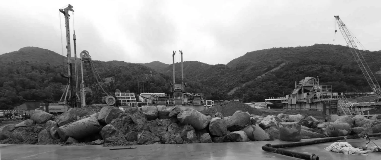
Fig. 4 Rock core sample
According to past experience, for ultra-deep rock construction of ground wall, the commonly used construction methods mainly include percussive drilling rig construction or rotary drilling rig with percussive drilling rig construction. In recent years, dual-wheel groove milling machines are also commonly used for rock construction. Generally, this approach is mainly applicable to the underground diaphragm wall construction where the depth of rock entrance is not high, the rock strength is not high, or the time constraint is relatively sufficient. Considering the actual geological conditions and construction schedule requirements, the previous construction method was analyzed and optimized, and the rotary excavator was selected to cooperate with the double wheel groove milling machine, and the construction technology of milling-drilling-milling was adopted to solve the problem of connecting the wall into grooves. Due to the ineffective cut of domestic slotting equipment in hard rock, Germany Bauer BC-40 double wheel grooving machine and BG-38 rotary drilling rig are used for construction.
When grooving, BC-40 groove milling machine is firstly used to construct the soil layer and the shallow rock layer. When entering medium and breeze rock layer, the footage speed decreases significantly. At this time, continuing construction will aggravate the loss of drilling gear and equipment, and the efficiency is too low. Therefore, the slot milling machine is temporarily moved to other slots for construction, and the rotary drilling rig equipped with roller cone drill is used to perform pre-crack drilling of rock strata, that is, two drilling holes with a diameter of 1.2m are constructed in the first and second cutting ranges of the slot milling machine, and the drilling depth is to the bottom of the underground continuous wall groove. Following the completion of the lead hole, the groove milling machine will re-create the groove milling construction. At this time, the original hard and entire rock formation has been fully pre-cracked, and the face has been expanded, as shown in Fig.5. The rock breaking footage speed of the groove milling machine can be increased by more than 2~3 times, and the drilling loss is significantly reduced. This method fully utilizes the benefits of a rotary drilling rig and double-wheel groove milling machine, significantly improving the construction efficiency of diaphragm wall and reducing the construction cost.
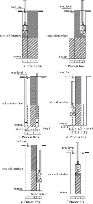
Fig. 5 Slotting method of diaphragm wall
3.2.2Vertical control of underground diaphragm wall
The design requires an allowable deviation of the perpendicularity of the diaphragm wall of 1/600, which is far higher than the specification requirements. Moreover, the fluctuation of the rock surface in the site is more severe, and the inclined rock strata are widely distributed, increasing the difficulty of controlling the perpendicularity of the trench. Based on this, the guide frame is set up at the slot hole mouth according to the laying out mark before slotting, and the milling head is fixed in the opening process of the grooving machine to serve as a guide. Throughout the slotting process, the deviation of each slotting direction can be monitored in real time by using its own verticality display system,as shown in Fig.6. Based on the construction situation and geological prospecting data, the operator can adjust the running state of the double-wheel slotting machine to drill into the junction of plagioclase and soft and hard stratum, and control the drilling speed and pressure in time to avoid the deviation of the milling head. When the groove deviation is large, the hydraulic rectifying plate of the groove milling machine is used to correct it, and the verticality is tested using ultrasonic inclinometer. By adopting the aforementioned measures, the quality of underground diaphragm wall is improved, and the design requirements are fully satisfied.
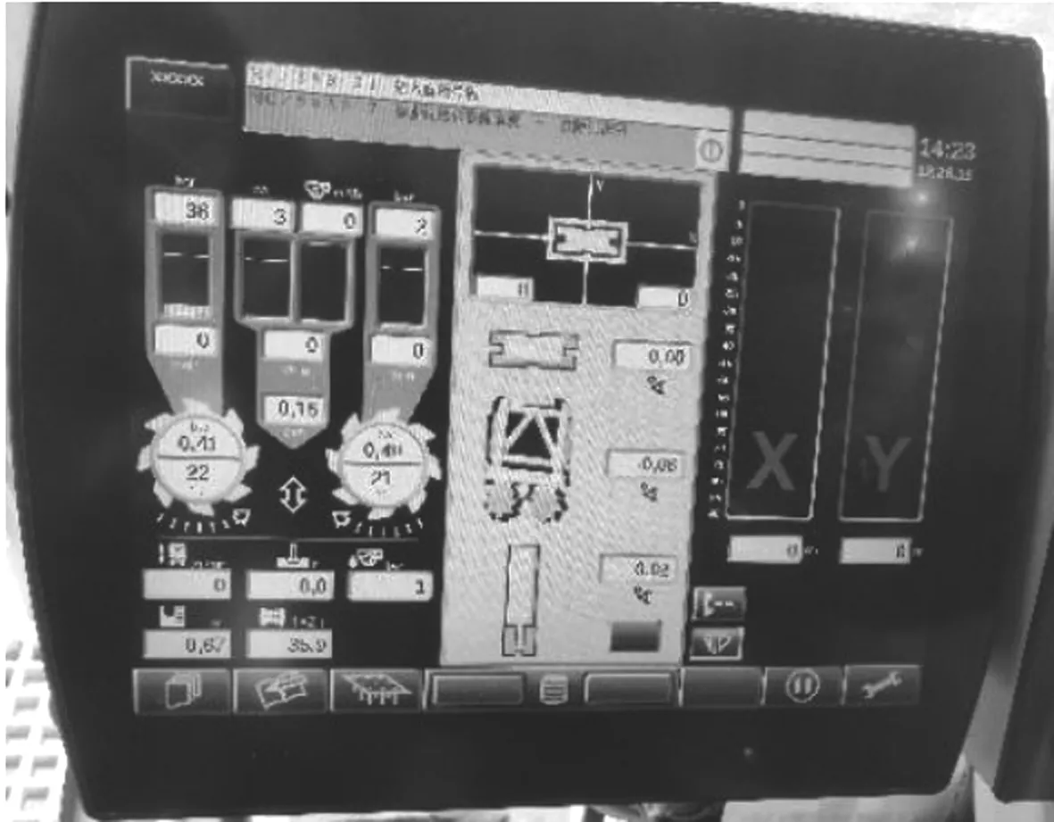
Fig. 6 Verticality monitoring system
3.3 Overall production and hoisting technology of super large steel cages
The longest length and width of the underground continuous wall reinforcement cage of the project are 59.5m and 5.6m, respectively, and the maximum dead weight of the reinforcement cage is 95t. By adding the additional load such as the sling, the total weight of is more than 110t, belonging to the super large and super heavy reinforcement cage.
3.3.1Steel cage production and reinforcement
The wall steel cage reinforcement is dense, three main bars are bonded together and the joint form is mechanical connection, as shown in Fig.7. If the steel cage is constructed by section hoisting, the main reinforcement and reinforcement form can lead to extremely difficult butt, and the hole to connect the steel cage takes a long time, which can easily cause the groove wall to collapse. Considering comprehensively, the floor wall steel cage is built and hoisted as a whole.
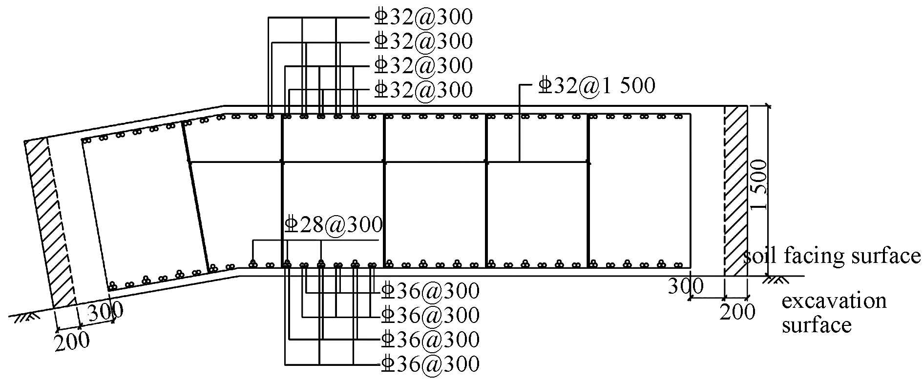
Fig. 7 Section of reinforcement cage
To strengthen the overall stiffness of the reinforcement cage and reduce the deformation during the hoisting process, the reinforcement cage as a whole and the lifting point must be reinforced. The longitudinal truss bars and horizontal truss bars of the reinforcement cage are produced by 32mm steel bars, with five trusses of the longitudinal truss bars spaced roughly 1m apart in the width direction of the reinforcement cage. The horizontal truss bars are arranged every 3m along the length of the cage. The layout of the truss bars can significantly enhance the overall stiffness of the cage. The lifting point of the steel cage is welded by a 25mm thickness steel plate skeleton for reinforcement, and the concentrated force of the lifting point is reasonably dispersed to the steel cage body.
To guarantee the machining quality of the steel reinforcement cage and forming speed, combined with the structure parameters of the reinforcing cage, through the analysis and practice, the optimal machining sequence for the wall reinforcing cage is the horizontal reinforcement of bottom layer→the longitudinal reinforcement of bottom layer→the longitudinal truss reinforcement→the horizontal truss reinforcement→the steel plate skeleton at lifting point→the acoustic pipe and grouting casing→the embedded reinforcement and shear reinforcement→the longitudinal reinforcement of upper layer→the horizontal reinforcement of upper layer→the horizontal sealing reinforcement.
3.3.2Hoisting equipment selection
Reinforcing cage hoisting adopts the construction method of double machine coordination and one-time overall hoisting, which is extremely difficult. The lifting equipment should meet the requirements of lifting capacity and lifting height.
1) Hoisting height requirements
The maximum length of the steel cage upright is 59.5m. With the 0.5m from the ground, the distance between the hook and the end of the boom is about 6m. The total height of the sling and wire rope below the hook is about 10m, then the vertical height of the lifting must be at least 76m.
2) Hoisting capacity requirements
When the reinforcement cage is in the upright state, the main crane has the maximum stress. The total lifting load is 110t, and the safety factor when the main crane is walking is set as 0.7, then the lifting capacity of the main crane must be at least 157t.
According to relevant research and construction experience, the maximum force of the auxiliary crane in the process of rotating vertically in the air from flat lifting is set to be 70% lifting load, so the load to be borne by the auxiliary crane is 77t. When the safety factor of the auxiliary crane is 0.8, the lifting capacity of the auxiliary crane should reach 96.25t.
3) Crane selection
Based on the hoisting capacity, hoisting height requirements and site conditions, Zoomlion ZCC5200S type 400t crawler crane is selected for the main crane, with arm length of 84m a turning radius of 16m, and 80t over-lifting counterweight. Under this situation, the lifting weight is 176t>157t, and the lifting height can reach 85m>76m, meeting the specification requirements.
XCMG XGC260 type 260t crawler crane is selected as the auxiliary crane. The arm length is 51m and the working radius is 12m, the lifting weight is 109t>96.25t, which meets the requirements.
3.3.3Layout of steel cage lifting point and selection of sling
If the position of the hoisting point of the steel cage is not calculated accurately, large deflection deformation will be produced, causing the weld to crack, the overall structure to break, and the lifting to be impossible. According to the law of bending moment balance, when the positive and negative bending moments are equal, the bending moment deformation is the smallest, as shown in Fig.8.

Fig. 8 Schematic diagram of reinforcement cage bending moment
Based on the calculation, fine-tuning is carried out in combination with the actual structural parameters of the reinforcement cage. The positions of lifting points and sling settings are shown in Fig.9.

Fig. 9 Schematic diagram of reinforcement cage hoisting
3.3.4Reinforcement cage hoisting construction
1) Hoist in place
Firstly the flatness and ground endurance of the foundation must be checked, and the working range and angle of the crawler crane can be adjusted. Then the center of the hook overlaps with the center of the steel cage must be ensured to install the sling.
2) Flat lifting test lifting
To ensure the safety of the steel cage hoisting scheme, the test hoisting was performed before the formal hoisting. Two crawler cranes are used to lift the steel cage for 50cm and hold it for 10min. The deformation and welding of the steel cage, as well as the working state of the crane, are observed. If there is an abnormality, the steel cage should be lowered again to determine the cause and take corresponding measures. If there is no abnormal situation, the lifting procedure can continue.
3) Turn upright in the air
After the completion of trial lifting, the main crane is gradually lifted, and the steel cage is inclined in the air. The secondary crane is gradually moving close to the main crane, and the steel cage is gradually adjusted to the vertical state.
4) Main crane movement
When the reinforcement cage is vertical, the secondary crane is detached from the hook, and the 400t main crane is directed to walk the reinforcement cage to the slot section. The crane should be kept stable during the walking process, and the distance from the ground cannot exceed 0.5m. The traction rope is attached on the reinforcement cage to prevent the shaking.
5) Rebar cage is lowered and the lifting point is adjusted
When the main lifting point is lifted, the lifting point transformation is gradually completed, as shown in Fig.10~Fig.12.
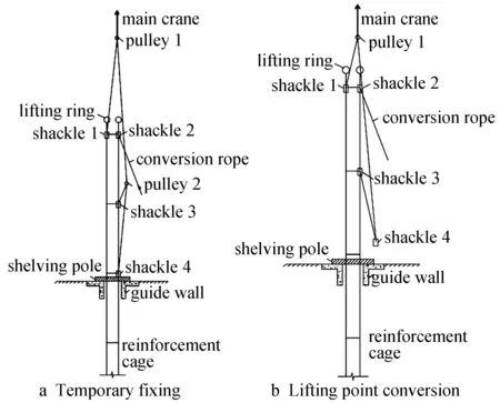
Fig. 10 Transformation process Ⅰ of steel cage lifting point
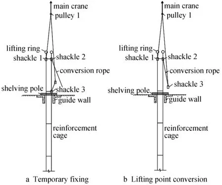
Fig. 11 Transformation process II of steel cage lifting point
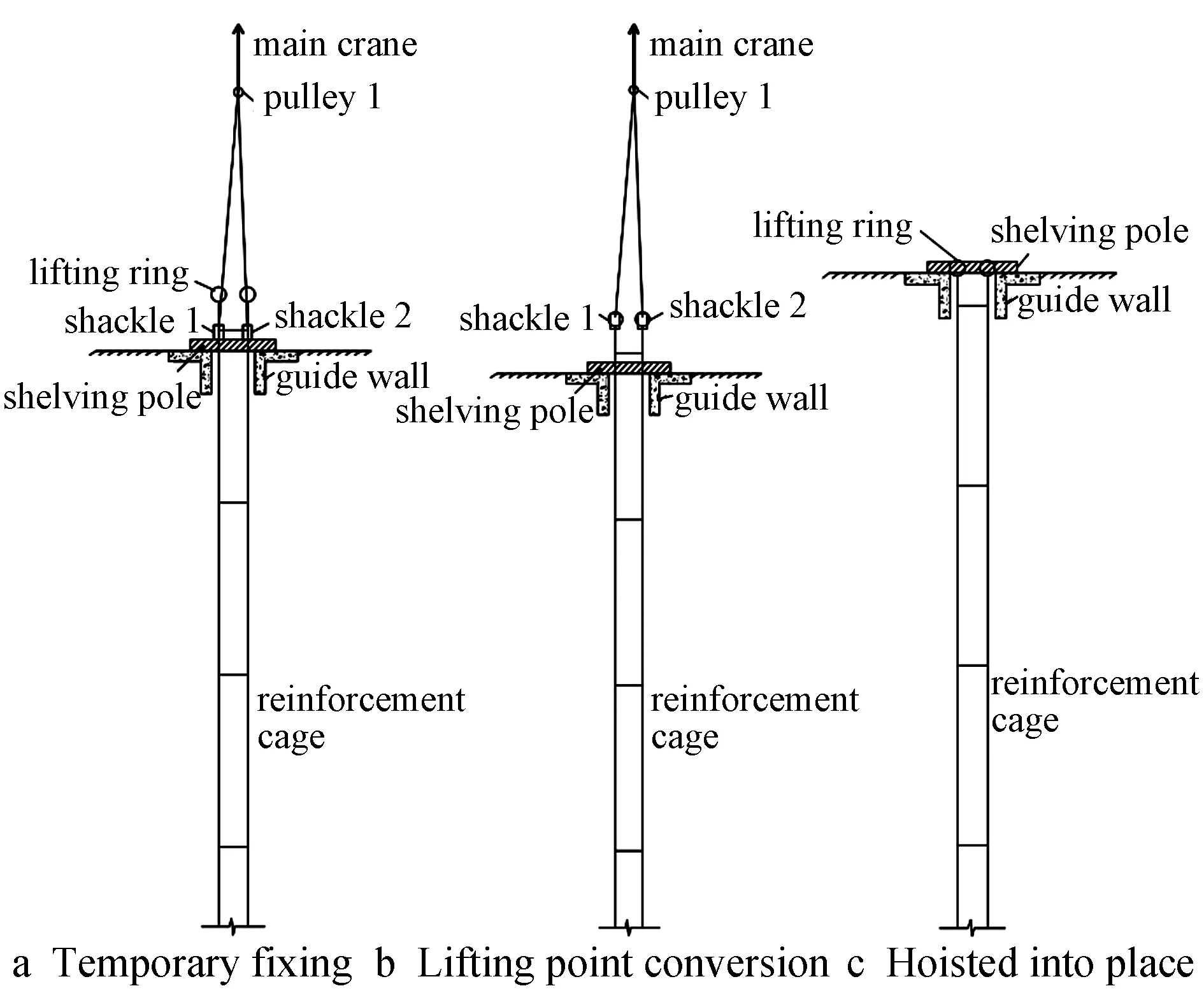
Fig. 12 Transformation process III of steel cage lifting point
3.4 Green mud circulation technology
Mud performance is one of the critical factors affecting the construction of an underground diaphragm wall. The main function of mud is to protect the wall by forming grooves, carrying drilling slags, cooling and lubricating, and so on. The engineering geological conditions are complex and the stratum stability is low. In addition, the thickness and depth of the ground wall are significant. The number of grooves and the amount of mud used in the construction process are large. All of these conditions might pollute the surrounding environment. Therefore, during the construction process, it is critical to choose green mud recycling treatment technology to ensure the quality and supply of mud.
The ground wall in this project has a circular layout, and the double-wheel groove milling machine is arranged within the circular road construction inside the ground wall. The convenience of construction is considered by reducing the mud transport distance and the loss. The mud circulation processing system is arranged in the inside wall. The system mainly consists of the pulp pool, the final settling basin, the clear water reservoirs, the slag and sand removal system, and so on. These conditions can ensure that the construction under the premise of reducing the slurry in amount of consumption cannot be affected and also the goal of green construction is achieved.
The operation principle of the whole mud circulation treatment system is described as follows.
1) First, the slurry is created by a mud mixing equipment in the pulping pool. After 24h, the proportion of mud, viscosity, sand content and other indicators are measured. Following the completion of the usage requirements, a mud pump is used to supply mud to the new slotted section.
2) The double-wheel slot milling machine starts to work. Two hydraulic motors drive the milling wheel, which rotates and cuts rock and soil bodies by breaking them into pieces, rolling them up, and mixing them with the mud in the slot. A centrifugal pump located between the two milling wheels pumps the mud containing debris through the mud pipe to the background desanding system.
3) The background desanding screen system is composed of a gravel separator and a desanding device. The mud pumped by the centrifugal pump of a milling trough machine is filtered and desanded on two levels. The clean mud enters the slurry storage box at the bottom of the desanding system.
4) As the tank’s depth increases and the mud is lost in the process, the mud needs to be replenished during the construction, and the mud is manufactured and transported to the tank through the pulping pool.
5) During underwater concrete pouring, the mud in the tank will be recycled to the sedimentation tank through the mud pump. If the indicators are qualified, the mud can be used to reduce the overall amount of mud.
When the performance index of circulating mud or recycled mud is not qualified, it becomes waste slurry. The waste slurry that is immediately removed will cause huge pollution to the environment, and it needs to be transported to the authorized off-site facility for treatment, which will be extremely expensive. The waste slurry produced during the construction process was treated harmlessly and the procedure is described as following. The waste mud is separated into water and mud cake through the mud filter press, as shown in Fig.13. The water is directed into the clear pool for reuse, and the mud cake produced by the filter press was dehydrated and can be directly transported to the filling area of the site. Then, the cost of mud treatment is effectively reduced, and the waste mud is fully utilized to avoid pollution and achieve green construction.
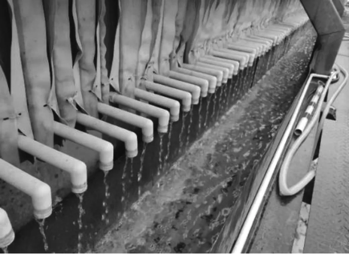
Fig. 13 Water separation diagram of mud filter press
4 The construction effect
By adopting essential construction techniques listed above, the underground diaphragm wall construction has achieved good results. After the underground diaphragm wall has been grooved, ultrasonic grooved meter is used to test the slot hole, and all of the indexes can meet the design requirements. According to the results, the trench verticality of the ground wall has completely reached 1/600 which met the design requirements, and the filling coefficient of concrete is less than 1.10, with an average of about 1.05, and the trench effect is good. The integrity of the wall body was tested by acoustic transmission method, and the quality of the wall was satisfactory. Basically, it was a class I wall, with no class Ⅲ and IV walls.
5 Conclusion
With the continuous development of underground space, the application scope of underground diaphragm wall is becoming more and more wide, and the increasingly difficult engineering geological conditions have become a serious problem. To construct an ultra-deep underground continuous wall under difficult geological conditions, the project adopts a number of advanced and applicable essential technologies that can effectively solve the construction problems.
1) In the newly filled area, cement-soil mixing piles are used to pre-reinforce the groove wall of underground continuous wall, which effectively improves the stability of the groove wall. The piles can also ensures the quality of the wall, and reduces the filling coefficient of concrete perfusion.
2) Using the milling-drilling-milling grooving method can increase the double wheel grooving machine into the rock construction of the air surface. It can also significantly improve the construction efficiency, and ensure the quality of construction.
3) In view of the super long and overweight underground continuous wall reinforcement cage, the safety of the overall production and hoisting construction process is ensured through the reinforcement and hoisting calculation and the selection of the reinforcement cage.
4) The efficient and green mud circulation treatment technology is adopted to achieve the goal of recycling and green construction.
