Diffraction separation and imaging based on double sparse transforms
2022-06-02XueChenJingJieCoHeLongYngShoJinShiYongShuiGuo
Xue Chen ,Jing-Jie Co ,*,He-Long Yng ,Sho-Jin Shi ,Yong-Shui Guo
a Hebei Key Laboratory of Strategic Critical Mineral Resources,Hebei GEO University,Shijiazhuang,Hebei 050031,China
b Hebei Nautral Resources Archives,Shijiazhuang,Hebei 050037,China
c The Third Hydrogeological Engineering Geological Brigade,Hengshui,Hebei 053000,China
Keywords:Diffraction separation Common-offset domain Diffraction imaging High-resolution linear Radon transform Curvelet transform Sparse inversion
ABSTRACT Reflection imaging results generally reveal large-scale continuous geological information,and it is difficult to identify small-scale geological bodies such as breakpoints,pinch points,small fault blocks,caves,and fractures,etc.Diffraction imaging is an important method to identify small-scale geological bodies and it has higher resolution than reflection imaging.In the common-offset domain,reflections are mostly expressed as smooth linear events,whereas diffractions are characterized by hyperbolic events.This paper proposes a diffraction extraction method based on double sparse transforms.The linear events can be sparsely expressed by the high-resolution linear Radon transform,and the curved events can be sparsely expressed by the Curvelet transform.A sparse inversion model is built and the alternating direction method is used to solve the inversion model.Simulation data and field data experimental results proved that the diffractions extraction method based on double sparse transforms can effectively improve the imaging quality of faults and other small-scale geological bodies.
1.Introduction
Petroleum exploration has been changed from structural exploration to lithology exploration.The imaging of small scale geological bodies such as breakpoints,pinch points,small fault blocks,caves,and fractures,is becoming a hot topic presently since these small-scale discontinuous geological bodies are often associated with oil/gas reservoirs.Conventional seismic exploration is mainly based on reflection waves assuming that the reflecting interfaces are smooth and infinite planes.Therefore,small-scale geological bodies cannot be effectively identified.Diffractions are responses of small-scale discontinuous geological bodies (Krey,1952;Kunz,1960),thus diffractions imaging method is an important method to detect small-scale geological bodies.The separation and imaging of diffractions from seismic records are of great significance to determine underground faults,pinch-outs and smallscale diffractors.
Diffractions and reflections have different kinematics and dynamics characteristics,furthermore,the energy of diffractions is usually one to two orders of magnitude weaker than the energy of reflections (Kamill et al.,1994).Even if the diffractions and reflections are accurately imaged,the diffraction wave will still be covered by reflection wave.Therefore,extraction of diffraction information and diffraction imaging are crucial for high-resolution imaging of small-scale geologic structures.
The diffraction imaging methods are mainly divided into two categories at present.The first kind method is to realize separation of diffractions and reflections at first,and then perform migration imaging for separated diffractions.The diffractions extraction methods are mainly based on the kinematic and dynamic differences between diffractions and reflections.Landa et al.(1987)used the common-offset profile to construct a common-diffraction point profile and realized diffraction imaging,which can detect local discontinuous and heterogeneous geological bodies.Fomel (2002)and Fomel et al.(2007) applied a prediction-error filter which is constructed with the local slopes of reflections to suppress reflections and enhance diffractions.The plane-wave destruction(PWD)method is a practical diffractions separating method.Taner et al.(2006)and Kong et al.(2012,2017)used the PWD filters in the plane-wave domain to separate reflections with linear characteristics and diffractions with hyperbolic characteristics.Zhao et al.(2016a,b) used the sparse inversion method to extract diffractions to identify discontinuous and heterogeneous geological information after PWD filtering.Nowak and Imhof (2004) used the hyperbolic Radon transform to separate diffractions in the prestack seismic records.Khaidukov et al.(2004) exploited the focusingdefocusing method to remove the focused reflection wavefield and finally obtain the diffraction wavefield.Based on their method,the reflection energy can be focused to the reflection point while the diffraction wave energies are scattered.In contrast,Berkovitch et al.(2009)focused diffractions to the positions of diffracted points by multi-focusing method.This is done by using a correlation procedure that coherently focuses diffraction energy on a seismic section by flattening diffraction events using a new local-timecorrection formula to parameterize diffraction travel time curves.Liu et al.(2014) and Lin et al.(2020) applied the singular value spectrum analysis method in the frequency-space domain to suppress reflection wavefield with strong energy and linear characteristics in the common-offset gathers where the kinematic and dynamic differences between the reflections and the diffractions were simultaneously used.Klokov and Fomel(2012)used the linear Radon transform to realize separation of diffractions and reflections in the common-imaging point gathers.Gong et al.(2016)developed an improved sparse apex-shifted hyperbolic Radon transform(ASHRT) to separate diffractions before stacking.Serfaty et al.(2017) used deep learning methods to separate reflections and diffractions.Xu et al.(2019) and Shen et al.(2020) used dynamic correction to flatten reflections and then applied singular value spectrum analysis method to separate diffraction wavefield in the common-shot gathers.Schwarz (2019) proposed the coherent wavefield subtraction method to extract diffractions using a variety of wavefront filters based on common-reflection-surface (CRS)method.Zhao et al.(2020) developed a 3D low-rank diffraction imaging method that used the Mahalanobis-based low-rank and sparse matrix decomposition method for separating and imaging 3D diffractions in the azimuth-dip angle image matrix.
Another type of diffraction imaging method is to realize separation and imaging of diffractions by modification of the migration operator in the imaging process.Zhu and Wu(2010)identified and imaged diffraction energy based on the energy-angle distribution differences in the local image matrix that reflection energy exhibits linear distribution along a certain dip direction,whereas diffraction energy shows a scattered distribution in the entire matrix.Zhu et al.(2013) used local dip filtering and prediction inversion jointly to separate diffractions,overcoming loss of low-dip information when diffractions are separated by a single dip difference.Yu et al.(2017)improved imaging condition based on dynamic properties of diffractions,reflections can be suppressed and diffractions imaging can be realized.Zhao et al.(2015) proposed a least-squares fitting method based on double exponential functions to study the amplitude function of diffractions,they modified the traditional Kirchhoff imaging conditions to form a new imaging formula,and used the polarity reversal of diffractions to eliminate strong reflections.Taking into account dynamic differences between reflections and diffractions in the common-shot gathers,Zhao et al.(2016a,b) developed a Mahalanobis-based diffraction imaging method by modifying the classic Kirchhoff formula with an exponential function,reflections can be attenuated and diffractions can be enhanced automatically.Liu et al.(2017) constructed an antistationary phase filter into the Gaussian beam migration with the help of dip-scanning and kinematic/dynamic ray tracing,and the anti-stationary phase filter operator was used to modify migration operator to obtain diffraction imaging profile.Zhang and Zhang(2014) proposed a method to accurately estimate the Fresnel zone in the dip-angle offset gathers,and the Fresnel zones related to reflections were muted and phases of diffractions were corrected,therefore diffractions in the migrated gathers can be enhanced(Li et al.,2018).Wang et al.(2020)and Kong et al.(2020)analyzed the differences of diffractions and reflections in the dipangle gathers,and realized wavefield separation in the dip-angle domain.
In this paper,we follow the idea of separating diffractions and reflections in the common-offset domain.According to the features that reflections are mostly smooth linear events in the commonoffset domain,while diffractions are still hyperbolic events,we propose a diffraction wave extraction method based on double sparse transforms.Two types of sparse transforms are exploited to represent diffractions and reflections.The high-resolution Radon transform is used to represent reflections,and the Curvelet transform is used to represent diffractions.A sparse inversion model is established,and the alternating direction method is used to solve the inversion model to realize separation of diffractions and reflections.The effectiveness of this method is verified by the separation and imaging results of two simulation data and a field data.The numerical results show that this diffractions extraction method based on double sparse transforms can get acceptable imaging quality of faults and other small-scale geological bodies,and the resolution of seismic exploration can be improved obviously.
2.Methodology
2.1.High-resolution linear Radon transform
The integration path of linear Radon transform is linear,so it can focus the linear events in seismic records.The forward and inverse transforms of the conventional linear Radon transform are defined as
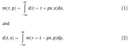
where m is the data in the Radon domain,τ is the intercept,p is the slope,d is the data in the time-space domain,t is the travel time,and x is the offset.
The forward and inverse Radon transforms can be expressed in the form of operators as follows

where L represents the Radon transform operator,LHis the conjugate transpose operator of L,and the objective function of the inversion model of the conventional Radon transform is defined as

For the high-resolution linear Radon transform,the L1 norm constraint condition is introduced to improve the resolution of conventional linear Radon transform.The objective function of the inversion model of the high-resolution linear Radon transform is

where α is a weighting factor,and m is the result of the Radon transform,which can be obtained by seeking the minimum value of the above objective function.High-resolution linear Radon transform has a better focusing effect on linear events than conventional Radon transform.
2.2.Curvelet transform
The strong sparseness of coefficients of seismic data in the Curvelet domain enables the Curvelet transform accurately express seismic signals with the least coefficients.In addition,multi-scale and directional characteristics of the Curvelet transform renders it a better focusing effect on curve events.
For the 2D data,the allowable condition of the window function in the Curvelet transform is
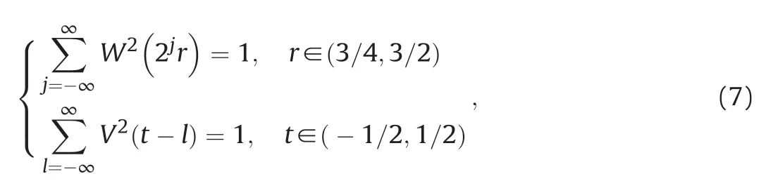
where r is the radius of polar coordinate,t is the variable in time domain,W(r)and V(t)are the radius and angle window functions in the polar coordinates (where W ≥0,V∈R),θ is a polar coordinate,and ω is the variable in frequency domain.The support intervals are r∈(1/2,2)and t∈[-1,1],respectively.And the window function in the frequency domain is defined as
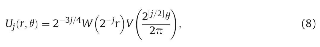
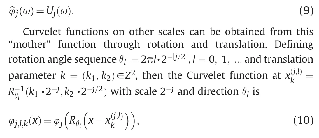
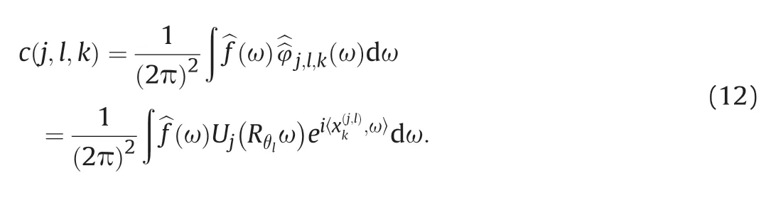
where Rθ is the rotation matrix.Curvelet transform can be written in the form of inner product of signal f and the Curvelet function:

According to the Plancherel theory,the formula of Curvelet transform in the frequency domain can be written as
2.3.Diffraction wave separation method
Assuming that dobsis the seismic data in the common-offset domain,which is composed of reflections and diffractions,the reflections events are linear or nearly linear with strong energy,and the diffractions exhibit hyperbolic events with weak energy in the common-offset domain.Suppose dlinerepresents the linear signal,corresponding to the reflection information,dcurverepresents the hyperbolic signal,corresponding to the diffraction information,and ε represents the random noise.Their relationship can be expressed as

Since the linear events can be sparsely represented in the Radon domain,it can be assumed that xline=Φdlineis sparse,where Φ represents the high-resolution linear Radon transform,and Φ-1represents the inverse high-resolution linear Radon transform.Similarly,events with curved shapes are sparse in the Curvelet domain.Assuming xcurve=Ψdcurveis sparse,Ψ represents the Curvelet transform,and Ψ-1is the inverse Curvelet transform.Therefore,Eq.(13) can be expressed as

Based on the sparsity of xlineand xcurve,the following sparsity inversion problem can be established
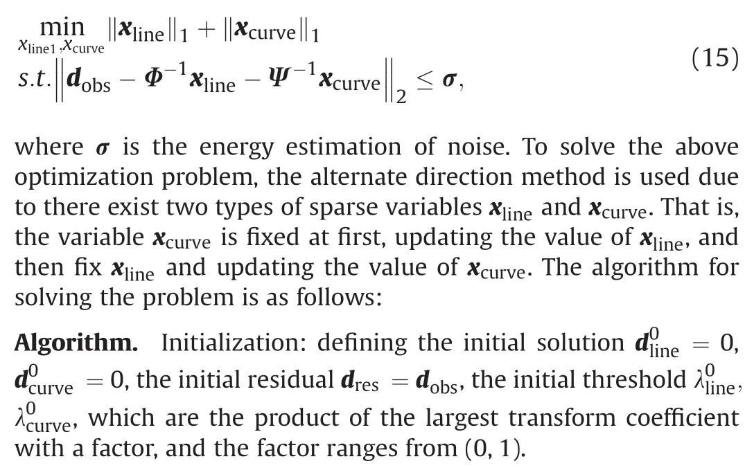
In this solving process,THλ(·)denotes the soft thresholding operation,can be reduced exponently,take small values.
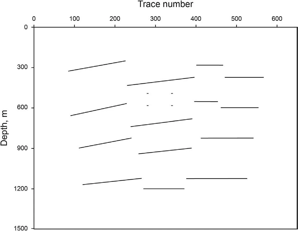
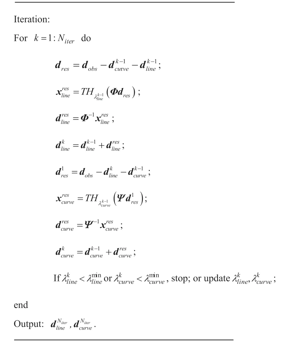
Fig.1.Schematic diagram of collapse model.
3.Numerical tests
3.1.Simple collapse model example
In this section,a collapse model data is used to verify the performance of the proposed method for diffraction separation.Fig.1 is a schematic diagram of collapsed model which contains 14 horizontal and inclined reflective interfaces of different lengths,and four independent diffraction points are set between the interfaces.The background velocity of model is 2000 m/s.Fig.2a shows the zero-offset synthetic seismic record of the collapse model.In this record,the reflections behave as linear events,while the diffractions appear as hyperbolic events,and the energy of diffractions is weaker than that of reflections.There is a certain degree of events superposition between the reflections and diffractions,and between different diffractions.Fig.2b and c show the separated reflections and diffractions according to the proposed method.There still left some diffractions in the reflection image due to the energy of reflections and diffractions are overlaped at the apexs of the diffraction hyperbolic events,but the method performs well in the whole result,and the diffractions are obviously strengthened in Fig.2c.
Fig.3a is the full wavefield imaging result obtained by one-way wave depth migration.Since the reflections energy is much stronger than that of the diffractions,the imaging profile mainly reflects large-scale geological information,and it is difficult to identify small-scale structures such as diffraction points.Fig.3b and c are the imaging results of the separated reflections and diffractions,respectively.The separated reflections imaging results reflect the situation of reflective interfaces,while the separated diffractions imaging can better reflect the situation of fault breakpoints,the boundary points of interface and the independent diffraction points.The imaging accuracy of diffractions are higher in the positions of diffraction points.Although there are some artifacts and noise at fault breakpoints and boundary positions,the results still reveal good performance of the proposed method in separating reflections and enhancing diffractions,which is beneficial to the identification and positioning of small-scale geological anomalies.
To test the anti-noise capability of the proposed method,we add Gaussian noise to the synthetic data with S/N of 5 as shown in Fig.4a.The amplitude of the noise is equivalent to that of the diffractions.The corresponding separated reflections and diffractions are shown in Fig.4b and c,respectively.Compared with reflections,diffractions have lower energy and are more affected by noise.The corresponding imaging results are shown in Fig.5.The imaging result of separated diffractions can still reflect the situation of fault breakpoints,the boundary points of interface and even the independent diffraction points very well.
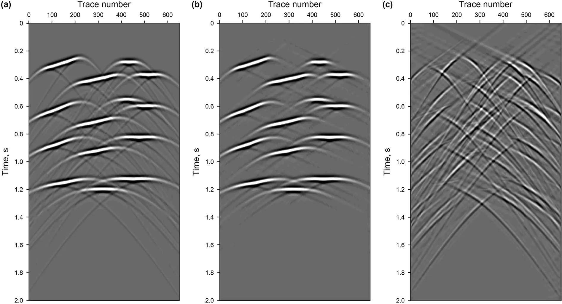
Fig.2.Synthetic seismic data and separation results of the collapse model

Fig.3.Full-wavefield imaging result and separated data imaging results of the collapse model

Fig.4.Noisy data with S/N of 5
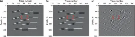
Fig.5.Full-wavefield imaging result and separated data imaging results of the noisy data
(a) Full-wavefield imaging result;(b) separated reflection imaging result;(c) separated diffraction imaging result.
3.2.Sigsbee 2A model example

Fig.6.A part of the Sigsbee 2A velocity model.
A part of the Sigsbee 2A data is used to verify the effectiveness of the proposed method for complex geological structures.The model is shown in Fig.6,in which some faults and point diffractors are marked by solid black lines and red circles,respectively.The zerooffset data is shown in Fig.7a,which contains complex reflections and diffractions.The separated results of reflections and diffractions by the proposed method are shown in Fig.7b and c.The method still has a good performance for complex data,the reflections and diffractions can be well separated.
To highlights the separation effect of diffractions,the time windows shown in Fig.7 are extracted from the full-wavefield data,the separated reflections data and the diffractions data,respectively,as shown in Fig.8 and Fig.9.The method shows good separation effect,and most of reflections in the wavefield can be separated and diffractions are enhanced in the two time-windows.A small defect is the apexes of the hyperbolic events of diffractions are mixed with reflection events,and diffraction energy will be misjudged as reflection energy,causing a certain amount of energy loss of diffractions.
Fig.10a,Figs.10b and 10c are the imaging results of the fullwavefield,the separated reflections and the diffractions,respectively.In the full-wavefield imaging result,the fault surfaces and point diffractors are covered up by reflection energy from continuous strata.The reflections imaging result mainly reflects largescale geological structures,though some diffraction energy still left in it.In the diffractions imaging result,the fault surfaces(marked by black circle)and point diffractors(marked by red circle)can still be clearly displayed compared with the full-wavefield imaging result although parts of reflection energy with steep dips remains,and the boundary shape of salt dome is also well preserved.The combination of the diffraction imaging and the fullwavefield imaging results can improve the positioning accuracy of diffractor targets,and provide more detailed structure information for seismic interpretation.
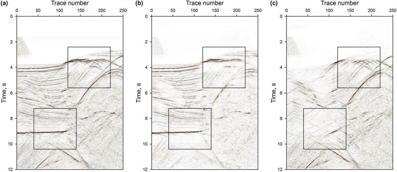
Fig.7.Full-wavefield seismic data and separation results of Sigsbee 2A data
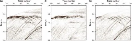
Fig.8.Shallow time window results of the Sigsbee 2A model data and separated data
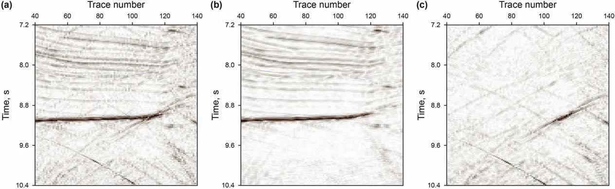
Fig.9.Deep time window results of the Sigsbee 2A model data and separated data
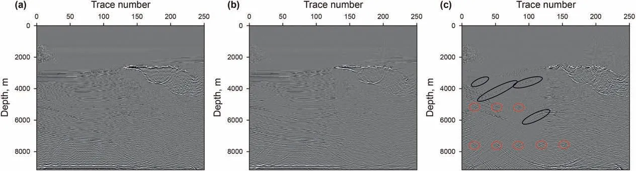
Fig.10.Full-wavefield imaging result and separated data imaging results of Sigsbee 2A
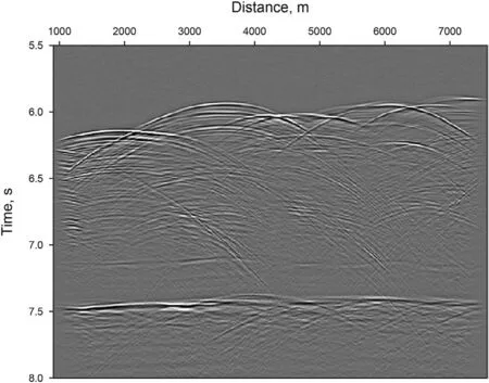
Fig.11.Field data DMO stacked section.
3.3.Field data example

Fig.12.Full-wavefield imaging result of field data.
A field data (open source data from Madagascar software) is used to further verify the effectiveness of the proposed method.The data is a deep water 2D line acquired to image the Nankai Trough subduction zone (Moore et al.,1990;Moore and Shipley,1993;Decker et al.,2017).We used a fragment of the line whose dip-moveout correction (DMO) stacked section is shown in Fig.11(Decker et al.,2017) to test our method.The corresponding oneway wave time imaging result is shown in Fig.12.The timemigration velocity model is from Decker et al.(2017).The shallow part of the data between 6 s and 7 s contain reflections and diffractions,and a few of diffractions are strong.This part of the data is complicated because of the complex geologic structures.The central part of the data approximately 7.1 s contain weak reflections and diffractions.The deeper part of the data approximately 7.5 s contain strong reflections and some weak diffractions generated from the discontinuities.
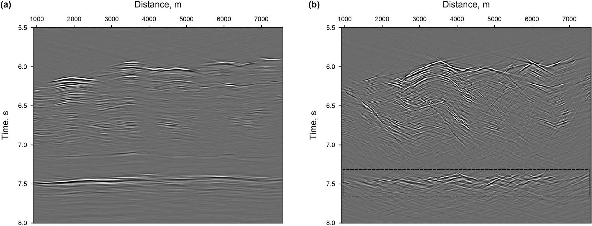
Fig.14.Separated diffraction imaging result
The corresponding separated results are shown in Fig.13.Fig.13a is the separated reflections and Fig.13b is the separated diffractions.There is a little remaining linear noise in Fig.13b because of the leakage of the diffraction energy.The method has a good performance for the whole data,the reflections and diffractions can be well separated especially for the central and deeper part of the data.Fig.14 shows the migration result of the separated reflections and diffractions.Compared with original data imaging result (Fig.12),both images highlight fault surfaces,and the separated diffractions imaging result (Fig.14b) is better in displaying finer discontinuities,such as those associated with the rough surface of the subducting plate crust,located near 7.5 s (Moore and Shipley,1993).
4.Conclusion
We have proposed an inversion method based on double sparse transforms to separate diffractions and reflections.In the common-offset domain,reflections appear as linear events and diffractions behave as hyperbolic events.Two transforms are used to represent these two types of signals:the high-resolution linear Radon transform is used to represent reflections,and the Curvelet transform is used to represent diffractions.A sparse inversion model was built and can be solved by an alternating direction method.Numerical results indicated that the proposed method can separate diffractions and reflections in the common-offset domain,and the imaging results can clearly display small-scale geological structures.By comparing the imaging results of diffractions and reflections,the diffractions imaging results have higher resolution for small-scale fractures,cracks,and heterogeneity.The extracted diffraction can be used as a kind of comparative data to help geologists study small-scale geological anomalies.
Acknowledgements
This work is supported by National Natural Science Foundation of China(41974166),Natural Science Foundation of Hebei Province(D2019403082,D2021403010) and Hebei Province “three-threethree talent project” (A202005009) and Funding for the Science and Technology Innovation Team Project of Hebei GEO University(KJCXTD202106).
杂志排行

Petroleum Science的其它文章
- Assessment of recoverable oil and gas resources by in-situ conversion of shale-Case study of extracting the Chang 73 shale in the Ordos Basin
- Pore structure evolution of lacustrine organic-rich shale from the second member of the Kongdian formation in the Cangdong Sag,Bohai Bay Basin,China
- Hydrocarbon generation history constrained by thermal history and hydrocarbon generation kinetics:A case study of the Dongpu Depression,Bohai Bay Basin,China
- Distribution characteristics and oil mobility thresholds in lacustrine shale reservoir:Insights from N2 adsorption experiments on samples prior to and following hydrocarbon extraction
- Extended hopanes and 8,14-secohopanes up to C40 in unbiodegraded marine oils from the Tarim Basin,NW China
- Porosity of gas shale:Is the NMR-based measurement reliable?