The influence of weak transverse magnetic field on plasma dissipation process in the post-arc phase in a vacuum interrupter
2022-06-01QilinSHI石奇霖HaoWU吴浩ZhaoYUAN袁召ZheTAO陶哲GuixiaLI李归霞WeiLUO罗威andWeiJIANG姜巍
Qilin SHI (石奇霖), Hao WU (吴浩), Zhao YUAN (袁召),*,Zhe TAO (陶哲), Guixia LI (李归霞), Wei LUO (罗威)and Wei JIANG (姜巍),*
1 State Key Laboratory of Advanced Electromagnetic Engineering and Technology, Huazhong University of Science and Technology, Wuhan 430074, People’s Republic of China
2 Key Laboratory of Pulsed Power Technology,Huazhong University of Science and Technology,Ministry of Education, Wuhan 430074, People’s Republic of China
3 School of Physics, Huazhong University of Science and Technology,Wuhan 430074,People’s Republic of China
Abstract Transverse magnetic field (TMF) contacts and applying external TMF are often adopted for reducing the ablation of the contact surface, but TMF will also affect the breaking performance of the vacuum interrupters.In this work, we investigated the influence of weak TMF on the expansion of the plasma in the post-arc phase with one-dimensional implicit particle-in-cell/Monte Carlo collision model, and we added an external circuit to the model to ensure the correctness of the calculation results.We simulated multiple magnetic field strengths(<30 mT),compared the plasma expansion process with the TMF strengths of 0 mT and 10 mT, and discussed the influence of metal vapor density on the insulation performance recovery of the vacuum interrupter.From the results,applying TMF with strength below 5 mT has little effect on the expansion of the plasma, and the TMF can increase the plasma density which improve the flow capacity of vacuum circuit breakers when the magnetic field above 10 mT,which is because the particles become more difficult to leave the discharge area under the force of the magnetic field.In general,we find that weak external TMF may adversely affect the breaking performance of the vacuum circuit breakers.
Keywords:vacuum circuit breakers,particle-in-cell/Monte Carlo collisions,transverse magnetic field, plasma
1.Introduction
Vacuum circuit breakers (VCBs) are widely used in the field of power transmission and distribution in medium voltage electrical networks due to their excellent arc extinguishing performance and environmentally friendly features [1, 2].Vacuum interrupters (VIs) are the key to determining the breaking performance of the VCBs, as the contacts begin to open to interrupt the fault current of the power system or the vacuum gap breakdown when a high enough voltage is impressed across it, and a vacuum arc will form between the opening contact[3].The breaking capacity of VIs restricts its application in high voltage, and the intense vacuum arcs(VAs) generated during the interruption of the VIs will leave considerable plasma and metal vapor in the gap, causing rebreakdown in the post-arc, and seriously restricting the breaking capacity of VIs[4].The axial magnetic field(AMF)and transverse magnetic field (TMF) have been extensively applied in the VIs [5, 6].Therefore, investigating the breakdown of the sheath expansion caused by the movement of charged particles under the influence of the magnetic field during the post-arc phase is of great significance for understanding the arc breakdown mechanism of the vacuum interrupter and improving the breaking performance.
In recent years, with the continuous improvement of computer performance and rapid progress of numerical modeling, particle-in-cell (PIC) model has been widely used to investigate the post-arc dynamics in VAs [7].PIC method is used to estimate how the residual plasma [8] and anode surface temperature [9] affect the breakdown process during sheath expansion in the post-arc phase.A one-dimensional full particle-in-cell/Monte Carlo collision(PIC/MCC)model is also used to investigate the influence of residual plasma drift velocity [10] and electron and ion temperatures [11] on sheath expansion of vacuum circuit breakers.Recently,a twodimensional PIC/MCC model has been developed in the post-arc stage of vacuum circuit breakers [12, 13].A onedimensional (1D) model of particle-in-cell/direct simulation Monte Carlo (PIC/DSMC) has been developed which was devoted to the simulation of the cathode and anode attachment zone of high current vacuum arcs [14-16].As for the formation and development of the vacuum arc, the axisymmetric swirl model is often used to describe the cathode spot physical process in VAs [17, 18].
There are experimental researches for the effects on the vacuum arc characteristics between TMF and AMF contacts during arcing [19, 20].In our previous researches, we built the experimental platform of AC breaking, which completed the experimental research of the post-arc current and cathode spots distribution in medium-high frequency vacuum arc[21, 22].TMF contact structure that causes the roots of the columnar arc to move rapidly over their surfaces has been proposed [3], some scholars also believe that the arc motion during arcing is worthy of attention rather than the expansion of sheath after current zero(CZ)[23,24],but the influence of TMF on re-breakdown during the post-arc phase is still worth investigating and rarely studied.There is still much residual plasma remaining in the vacuum gap after the current zero,and the movement of the residual plasma particles under the action of the reapplied voltage may play a significant role in the re-ignition mechanism in the early recovery phase[25, 26].Even with all these works, sheath expansion in the post-arc phase and effects of the external magnetic on the arcing period have received sufficient attention to date,however, the influence of the magnetic including AMF and TMF fields in the post-arc phase has been rarely studied.Because of a positive effect on improving the interruption ability of the vacuum interrupter, an external magnetic field has been widely used,therefore, creating a physical model to estimate how the magnetic affect the post-arc process in plasma dissipation and sheath expansion is necessary.
In this work,we have developed a 1D implicit PIC/MCC model.In order to ensure the correctness of the calculation results and the self-consistent of the model, we added an external circuit model.In our model, we researched the influence of weak external TMF (<30 mT) on sheath expansion in the post-arc phase in VCBs.The paper will be organized as follows: in section 2, the physical models and numerical models are presented.The results and discussion are given in section 3.Finally, the conclusions are drawn in section 4.
2.Model description
2.1.Physical models
2.1.1.General consideration.We develop a 1D implicit PIC/MCC model simplified from the schematic diagram of our previous experiments [21] shown in figure 1 to simulate the plasma dissipation process in the post-arc phase.The calculation position of the 1D3V implicit PIC-MCC model is located at the axis of symmetry and the model ignores the radial motion of the particles.Based on the actual experimental loop, the inductance and resistance of the external circuit in figure 1 mainly come from the wire,and the stray capacitance of the vacuum interrupter to the ground is represented by a capacitance C connected in parallel with the discharge gap.The possible influence of the external circuit on the discharge gap can be simulated by considering the R,L, and C.We regard the voltage source V(t) as DC power,because the post-arc plasma dissipation process which we are concerned only lasts for tens of microseconds, while the voltage amplitude varies slightly during this time.The parameters of external circuit are set as follows: R = 20 Ω,L = 3.5 mH, C = 0.4 μF and V (t) = -40.5 kV [8].The calculated transient recovery voltage (TRV) is obtained by solving Poisson’s equation without plasma in the contact gap shown in figure 2.The external circuit diagram is close to the structure of our experimental loop, and experimental results can be referred to [21, 22].Discharge process is simulated with two parallel contacts at a distance of z = 10 mm which is consistent with the parameters in our experiment [22].In our simulation,the contact material is copper,which is widely used in VCBs.The voltage class of VIs is 40.5 kV.The velocity of particles is distributed by Maxwell at the temperature of Te= 3 eV for electrons and Ti= 2 eV for Cu2+ions [8], and their direction is random.It should be noted that this temperature is given, not the result of a selfconsistent calculation.We apply an external TMF which is parallel to the contact surface and uniformly distributed throughout the contact gap.Two different TMFs, 0 mT and 10 mT are considered in the simulation.
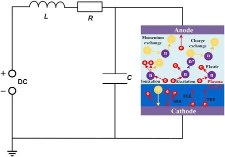
Figure 1.External circuit diagram.

Figure 2.Variation of transient recovery voltage and source voltage obtained by solving the circuit equation without plasma with time.
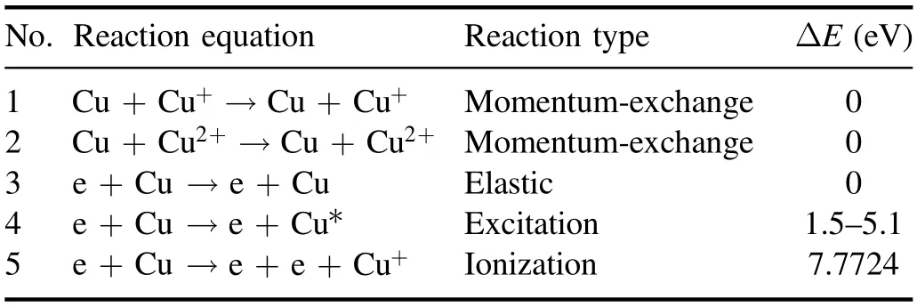
Table 1.Particle collision response program added.
2.1.2.Particle and collision.Average charge number of the copper ions is usually 1.85[27]when the arc is extinguished,so we assume that the remaining plasma in the gap at current zero-crossing instants is composed of electrons and Cu2+ions[8], and Cu+is all produced by ionization.Therefore, we considered the momentum-exchange between Cu+and Cu2+ions and elastic, excitation and ionization reaction between Cu atoms and electrons which were shown in table 1.As shown in figure 3, we redrew the collision cross section including the reaction of electrons and copper atoms through the code to verify its accuracy, where the left side of the elastic collision curve is drawn through the extrapolation method.The energy thresholds of the excitation reaction corresponding to curves 2-5 from figure 3 are 1.5, 1.5, 3.8, and 5.1 eV,respectively.It is worth mentioning that since the temperature of the Cu atoms we assume is not high enough to cause Cu to produce a large amount of secondary ionization, and the metal vapor pressure is generally much lower than atmospheric pressure, its degree of ionization is generally not more than 10%,thus,in our simulation model,ionization to produce Cu2+ions is not considered.The cross-sectional data between electrons (e) and Cu atoms can be obtained from the openaccess website Lxcat and others can be obtained from [28-30].

Figure 3.Electron-impact elastic and excitation and ionization of cross section of Cu, including an elastic and four excitation and an ionization cross sections.
The time for sheath expansion during the post-arc phase is generally tens of microseconds,however,the dissipation of metal vapor usually takes more than a few milliseconds.Therefore,in our simulation,the distribution of metal vapor is considered to be constant.The initial density of plasma is 2×10¹⁷m-3; the density of metal vapor is 1022m-3[8].
Besides, possible surface processes for the breaking process of VCBs include secondary electron emission (SEE),field electron emission (FEE) and thermal electron emission(TEE) which are shown in figure 1.We consider the SEE from the cathode bombardment by electron and ion (e, Cu+,Cu2+→ e), and estimate the SEE probability induced by electrons from the equation (1) of which curve is roughly consistent with [31] and SEE coefficient of ions is 0.1

EpandEmare the energy of the primary electron and the energy at which the coefficient reaches its maximum value.δandδmare the SEE coefficient we need to calculate and the maximum SEE coefficient respectively.
2.1.3.External circuit.There is an interaction between the plasma and the external circuit, which together determine the distribution of the electric field within the gap.Figure 1 shows the external circuit model,while R,L,and C,respectively,are the resistance, inductance, and capacitance.The coupling between the external circuit and discharge area can be achieved numerically.This method in[32,33]is used to solve the circuit equation(2)and the electric field flux equation(3),and charge conservation equation (4), and Poisson’s equation (5).
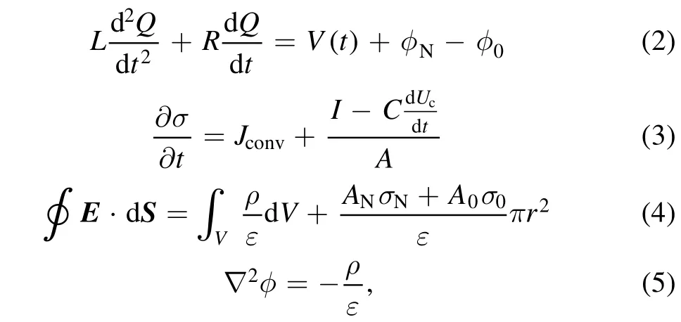
where Q is the charge of the capacitor plate C, σ is the total charges carried by the plates of VIs,A is the electrode area,ρ is the current density in discharge area, and Jconvis the conduction current.
2.2.Numerical models
To simulate the sheath expansion and the charged particles’movement under TMF, we developed a 1D3V implicit PIC/MCC model [34].Our PIC/MCC model starts from the initial conditions and iteratively updates the values of particles and fields.The field equations are calculated by solving Poisson’s equation and the given boundary conditions.The MCC algorithm is used to process elastic, excitation, and ionization between Cu atoms and electrons which is also used to process elastic and momentum-exchange between electrons and Cu+,Cu2+ions,respectively[35].A detailed description of our model is presented in[36],and it has been successfully applied to the research of different types of plasma, such as magnetized capacitively coupled plasma [37, 38], micro discharge plasma,and so on.Besides,we added AMF and TMF codes based on our PIC model to simulate the effect of an external TMF on plasma dissipation during the post-arc phase [37, 38].
Generally,the implicit method has fast computing speed,no convergence problem, the only numerical stability limit is the Courant condition.In the simulation process, the space step dx and the time step dt should be set properly to meet the following conditions:dx/dt > Vthand an empirical condition of dx/dt < 10Vth, where Vthis the thermal velocity.In addition, it is not enough for the implicit method to yield a stable numerical solution, and the actual physical correctness must be guaranteed as:dx < λDand dt < 0.2/ωpe[39],where λDis Debye length and ωpeis plasma frequency.Considering the above requirements,we set the space step dx = 1×10⁻⁴m and the time step dt = 2×10-11s.
In our 1D3V implicit PIC/MCC simulation code [40],the position and velocity information are updated alternately,where velocity is updated with a full 3D electromagnetic field;therefore,the E×B drift is included in the phase space[37].Nevertheless, owing to the E×B drift, space charge separation will occur, resulting in an electric field along the direction of E×B [38].Our future work will establish a 2D implicit PIC model, which will correctly reflect the E×B drift.Although literature [41] indicates that the AMF makes no effect on the residual plasma expansion during the post-arc phase, a 1D PIC model cannot completely take into account the E×B drift motion,so the effect of the AMF needs further discussion.Besides, the error caused by the E×B drift motion to the model will gradually increase to non-negligible as the magnetic field strength increases,so we mainly discuss the expansion of plasma with weak magnetic fields.Although a one-dimensional PIC/MCC model cannot completely and accurately describe the effects of TMF, it can still reflect the behavior of the plasma, which has been verified in our previous work [38, 42], so it is still effective.
3.Results and discussion
3.1.The influence on plasma density expansion with and without transverse magnetic field
To explore the influence of TMF on the recovery of the insulation property during the post-arc phase, the external circuit conditions are consistent with the previous settings,and TMF Btwith the strength of 0 mT and 10 mT, and take cathode as position 0 and the plasma evolution results are obtained.Figure 4 shows the spatio-temporal evolution of electron density.For 0 mT,the plasma is mainly concentrated in area 4-8 mm away from the cathode,with the peak density exceeds 4.7×10¹⁸m-3.For 10 mT, the TMF causes the electron density to increase,and the thickness of the sheath is significantly shorter,and the plasma density distribution shifts to the cathode side of the DC power supply.This is because the electrons heated in the DC sheath region are bound by the magnetic field and cannot move to the main plasma region,so they exhibit an offset in the density distribution.The increase of the magnetic field strength reduces the cyclotron radius of the electron, and the electron means free path decreases,increasing the probability of collision,which in turn increases the ionization rate.Due to the lower amplitude of applied voltage, the electrons with higher energy are more likely to escape from the discharge gap, which causes the right end of the curve in figure 5 at 0.5 μs to be lower than that at the initial time of 0.05 μs.As shown in figure 2, the transient recovery voltage continues to increase during 0.5-5 μs, the electrons are accelerated in the electric field, and the proportion of electrons at higher energy in figure 5 increases.At 5-10 μs, the transient recovery voltage further increases, the proportion of electrons at lower energy decreases.At the same time,the plasma density increases,which is shown in figure 4,the probability of collisions between particles increases, so that the proportion of electrons at higher energy no longer increases.

Figure 4.Spatio-temporal distribution of electron density at external TMF of: (a) 0 mT, (b) 10 mT.

Figure 5.The variation in the EEDF over time at external TMF of (a) 0 mT, (b) 10 mT.
The post-arc current Ipacis an important parameter that can reflect the interrupting performance of VCBs.Figures 6(a) and (b) show the spatio-temporal evolution of electron current density at external TMF of 0 mT and 10 mT,respectively.The electron current density near the interface between the plasma and the sheath peaks over 2000 A m-2shown in figure 6(a).The reason for this phenomenon is that the secondary electrons emitted from the cathode are accelerated by an electric field through the sheath area and its directional movement speed peaks at the interface.What is more, electrons in the plasma move away from the sheath,creating electrical currents which cause sheath expansion.The above two points explain why the electron current density near the interface between the plasma and the sheath is the largest.Cu2+moves toward the cathode and anode,under the electric field as shown in figure 7, since there is no newly generated Cu2+supplement, and Cu2+density shows a slow decay trend from the middle to the electrodes at both ends.Contrast to 0 mT, the TMF delays the dissipation rate of Cu2+, which corresponds to the increase in current density shown in figure 8.These indicate that the TMF increases the gap flow capacity in the post-arc phase.From table 1, due to the equal amount of Cu+and electrons produced by the ionization reaction, the density evolution trend of Cu+is similar to that of electrons.The numerical simulation results of plasma and current under external TMF in the post-arc phase are verified by experiments [43].

Figure 6.Spatio-temporal distribution of electron current density at external TMF of: (a) 0 mT, (b) 10 mT.

Figure 7.Spatio-temporal distribution of Cu2+ ion density at external TMF of: (a) 0 mT, (b) 10 mT.
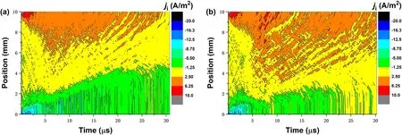
Figure 8.Spatio-temporal distribution of Cu2+ ion current density at external TMF of: (a) 0 mT, (b) 10 mT.
Figures 9 and 10 show the spatio-temporal evolution of the mean energy of electrons and Cu2+ions, respectively.From figures 9(a) and 10(a),we know that the mean electron energy in the quasi-neutral plasma region maintains a value below 50 eV, while the mean electron energy in the sheath region can reach up to 300 eV.The Cu2+ions energy closer to the cathode sheath region is higher because the ions are accelerated by electrical force in the sheath area.The mean energy of particles is positively related to time because the sheath gradually stops growing and the voltage across the gap increases,which strengthens the electric field near the cathode, as shown in figure 11.For 10 mT, shown in figures 9(b) and 10(b), the mean electron energy near the interface between the sheath and plasma zone is generally higher than 100 eV, and the closer to the cathode sheath region, the higher Cu2+ions energy.Compared with the results in figures 9 and 10, TMF prevents the electron and Cu2+ions from moving completely along the direction of the electric field lines,and the energy obtained by accelerating in the electric field is reduced which is manifested by a decrease in the peak value of mean energy of electron and ion.
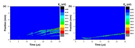
Figure 9.Spatio-temporal distribution of mean electron energy at external TMF of: (a) 0 mT, (b) 10 mT.
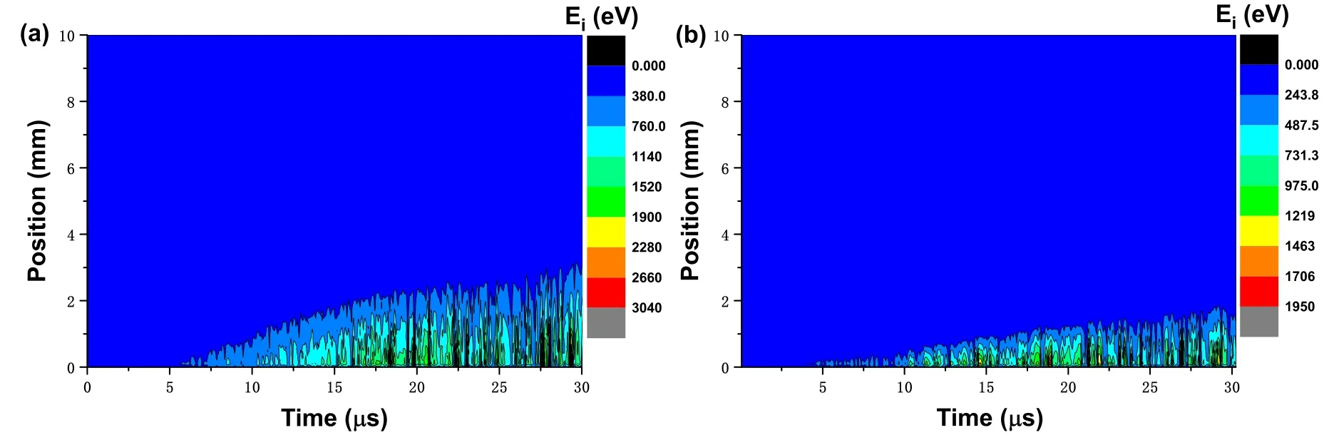
Figure 10.Spatio-temporal distribution of mean energy of Cu2+ ion at external TMF of: (a) 0 mT, (b) 10 mT.
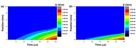
Figure 11.Spatio-temporal distribution of electric field at external TMF of: (a) 0 mT, (b) 10 mT.
3.2.The effect of different transverse magnetic field strengths
To explore the influence of different transverse magnetic field strengths on insulation recovery ability during the post-arc phase, we scanned the peak electron density and the corresponding coordinates under the TMF strength from 0 mT to 30 mT, as shown in figure 12.When the applied TMF is below 5 mT, the particle density does not increase significantly, even decreases at certain values.Although a slight increase in the TMF strength increases the collision probability, the increase in the electron energy makes it easier to leave the discharge area, and finally shows that there is no obvious effect on the plasma density when external TMF strength below 5 mT.When the TMF strength increases above 10 mT,the electron density increases by 1-2 orders of magnitude.At the same time, the position corresponding to the peak electron density is closer to the cathode.This is because the electrons heated in the direct current sheath area are bound by the magnetic field and cannot move to the main plasma area.Therefore, the density distribution is characterized by a deviation to the plate on the side of the direct current(DC) power supply.With the increase of the magnetic field,the sheath gradually becomes shorter and the field strength near the cathode increases, which increases the energy of the electrons, makes it easier for the electrons to escape from the discharge area and reduces the plasma density.In addition,the increase of the magnetic field reduces the cyclotron radius of the particles and increases the collision probability of the main plasma region, which leads to an increase in plasma density.These two factors affect the density of plasma together.The increasing of plasma density and the thinning of the sheath thickness make the peak position closer to the cathode side.Though the external TMF has an effect on the peak electron density, it is found that when the applying strength of external TMF is below 5 mT, it no longer has a significant effect on evolution of plasma density.
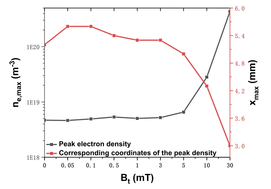
Figure 12.Electron density peak values and corresponding positions under different transverse magnetic field strengths within 30 μs.

Figure 13.Sheath thickness over time.The applying TMF strength:Bt = 0 mT, 10 mT and 20 mT.
To explore the influence of applied TMF strength on the sheath expansion,set the metal vapor density to 1017m-3,the applied TMF was 0 T, 10 mT, and 20 mT, and other simulation parameters unchanged.Figure 13 shows how the sheath expands over time under different levels of TMF strength,which can be found that the expansion of sheath becomes slower with the increase of the TMF strength.Compared with the result without TMF,the applying strength of 10 mT TMF increases the sheath expansion process duration from 13 to 31 μs, while TMF strength increases to 20 mT, the sheath only develops 3 mm in 40 μs.
3.3.The effect of metal vapor on sheath expansion under various transverse magnetic fields
The speed of sheath expansion determines the interrupting ability of VCBs.The variation of sheath thickness is affected by the metal vapor and TMF.In order to explore the growth rate of the sheath at various metal vapor densities under various TMF strengths, PIC is used to simulate the sheath expansion in the post-arc phase.Figures 14(a) and (b) show how sheath thickens over time at various metal vapor densities without TMF and with TMF strength Bt= 10 mT,respectively.The initial plasma density is 2×10¹⁷m-3and initial metal vapor densities are set to 0, 1021m-3, 5×10²¹m-3, 1022m-3and 1023m-3.The growth rate of the sheath slows down with the metal vapor density increasing, indicating that the presence of metal vapor hinders the sheath expansion because the metal vapor intensifies the collision between particles.Compared with the condition without metal vapor which causes that the sheath expands to anode within 8 μs, the sheath expansion process duration increases to 35 μs when metal vapor density is set to 5×10²¹m-3.It takes longer for the sheath to develop to anode when metal vapor density increases to 1022m-3.We reasonably infer from the above results that with the metal vapor density increases, the speed gradually slows down the development of sheath, the metal vapor density at a certain value will eventually stop the sheath expansion, i.e.the metal vapor density is above a certain value when the plasma discharge can be maintained.For a given applied TMF Bt= 10 mT, it has little effect on the sheath expansion when compared to no magnetic field case without the metal vapor while it slows the sheath expansion at other metal vapor densities because the charged particles (e, Cu+, Cu2+) perform the cyclotron motion under the action of TMF, and the greater the metal vapor densities,the more electrons produced by the new ionization, and the more significant the effect of the magnetic field.Based on the continuous transition model, the sheath expansion velocity is strongly linked to the plasma density after current zero which is consistent with the results we have shown in figures 4 and 13.
Figure 15 shows how the average density of particles(including electron and Cu+, Cu2+ions) varies over time.In figure 15(a), TMF strength Bt= 0 mT, Cu2+density can dissipate from gap in 18 μs.Since this model does not consider the ionization to produce Cu2+ions, there will be no increase in Cu2+ions.Actually,the yield of Cu2+ions is also far less than its dissipation rate.The density of electrons will drop first because of the low voltage in the gap at the initial moment during the post-arc phase which contributes to the number of electrons newly ionized being less than the number of electrons moving out of the discharge area.From 3 μs,the density of electrons and Cu+particles began to increase,which is caused by the increased ionization rate caused by the continuous increase of voltage.It can be seen from equation(5)in table 1 that the numbers of electrons and Cu+produced are equal which explains that the upward trends of electron and Cu+ions densities are similar.After 25 μs, the density of electrons and Cu+began to decline,and the plasma dissipated completely from the discharge gap within 36 μs,indicated the discharge could not be maintained.Since the temperature of the electrons is higher than that of the ions,the thermal movement speed is greater, so it drops slightly faster than Cu+.
When the TMF strength increases to 10 mT, the evolution trend of average particle density is similar to that under the TMF strength of 0 mT, but there are differences in the time scale and number of particles.The densities of electrons and Cu+ions multiply because the increase of TMF strength increases the ionization rate.The increase of plasma density increases the collision probability which hinders Cu2+particles from dissipating from the gap.The time for Cu2+ions to completely leave the gap increases from 18 μs to 25 μs.

Figure 14.Sheath thickness with the TMF strength:(a)0 mT and(b)10 mT over time.Metal vapor densities:no vapor,1021 m-3,5×10²¹ m-3, 1022 m-3, 1022 m-3 and 1023 m-3.

Figure 15.Variation in average density of particles with time.The applying TMF strength: (a) 0 mT and (b) 10 mT; metal vapor density:5×10²¹ m-3.
4.Conclusion
To simulate TMF on breaking performance in the post-arc phase, we develop and implement a one spatial dimension implicit PIC-MCC model with three velocity dimensions.This model considers various collision reactions, including elastic, excitation, ionization collisions, and momentumexchange.Secondary electron emission is also considered.To ensure the self-consistency of calculations,we add an external circuit model.We discuss the expansion of plasma density and the corresponding position of the peak density with the change of transverse magnetic field, and compare the plasma density, current density, electric field, etc under two conditions of no external magnetic field and external TMF strength Bt= 10 mT.Some significant features are obtained and analyzed.
(1) When applied TMF strength is below 5 mT, it has no significant effect on the plasma expansion in the post-arc phase.While magnetic field strength increases above 10 mT,the plasma density rises significantly and the position corresponding to the density peak is shifted to the cathode side.This indicates that applying external TMF during the post-arc phase can increase plasma density to improve flow capacity, which is because the charged particles move in the discharge area under the action of the magnetic field,making it more difficult for the particles to leave the discharge area.This shows that applying external TMF has an adverse effect on the breaking performance of the vacuum circuit breakers,which is consistent with the results measured in the experiment that the residual plasma density increases during the post-arc phase when external TMF is applied.
(2) Increasing the strength of the TMF or increasing the density of metal vapor will make the sheath expansion slow down, the former is caused by the cyclotron motion of charged particles under the magnetic force,and the latter is due to the fact that the increase in the density of neutral particles increases the probability of collisions and hinders the movement of electrons.The increase in the strength of the TMF and the metal vapor density is not conducive to the recovery of the insulation performance of the vacuum circuit breaker.
Based on the above descriptions, we believe that increasing external TMF strength during the arcing phase and reducing external TMF strength during the post-arc phase can improve the breaking capacity of vacuum circuit breaker.
All the work in this paper is based on a 1D program,but it has limitations when simulating E×B drift motion because the conductivity along the magnetic field direction may be more than an order of magnitude higher than that perpendicular to the magnetic field direction.Our future work will extend to the 2D PIC model, which will better simulate E×B motion.In the future,we will calculate the temperature of contact surface selfconsistently and we will also continue to explore the expansion of plasma under a strong magnetic field in the post-arc phase.
Acknowledgments
This work was supported by National Natural Science Foundation of China (Nos.11775090, 51807069 and U1766211).
ORCID iDs
杂志排行
Plasma Science and Technology的其它文章
- Integrated data analysis on the electron temperature profile of HL-2A with the Bayesian probability inference method
- Prompt acceleration of a μ+ beam in a toroidal wakefield driven by a shaped steeprising-front Laguerre-Gaussian laser pulse
- Numerical study of the effect of coflow argon jet on a laminar argon thermal plasma jet
- On the green aurora emission of Ar atmospheric pressure plasma
- Dynamic characteristics of multi-arc thermal plasma in four types of electrode configurations
- Formation and destruction of striation plasmas in helium glow discharge at medium pressures
