A novel algorithm for distance measurement using stereo camera
2022-05-28ElmehdiAdilMohammedMikouAhmedMouhsen
Elmehdi Adil|Mohammed Mikou|Ahmed Mouhsen
1MISI Laboratory,Faculty of Sciences and Techniques,Hassan First University of Settat,Settat,Morocco
2IMII Laboratory,Faculty of Sciences and Techniques,Hassan First University of Settat,Settat,Morocco
Abstract Distance estimation can be achieved by using active sensors or with the help of passive sensors such as cameras.The stereo vision system is generally composed of two cameras to mimic the human binocular vision.In this paper,a Python-based algorithm is proposed to find the parameters of each camera,rectify the images,create the disparity maps and finally use these maps for distance measurements.Experiments using real-time images,which were captured from our stereo vision system,of different obstacles positioned at multiple distances (60-200 cm) prove the effectiveness of the proposed program and show that the calculated distance to the obstacle is relatively accurate.The accuracy of distance measurement is up to 99.83%.The processing time needed to calculate the distance between the obstacle and the cameras is less than 0.355 s.
KEYWORDS computer vision,disparity maps,distance measurement,Python,stereoscopic processing
1|INTRODUCTION
Over the past years,a lot of research studies have been focussed on calculating distance to objects.These studies can be separated into two categories:active and passive methods.In active methods,distance can be found using RADAR(Radio Detection and Ranging),LIDAR (Light Detection and Ranging)or ultrasonic sensors.The principle of the RADAR is to emit a radio-frequency wave modulated by a signal towards a target.After reflection on the object,the received wave is analysed by the receiver.Since the speed of propagation of electromagnetic waves in the air is known,the distance to the obstacle can be deduced [1].The other method is based on LIDAR and it's widely used in the field of robotics for the navigation of robots in unknown environments[2].It emits an infrared laser beam and analyses the beam reflected by the obstacle in the laser firing axis.The ultrasonic sensors can also measure the camera-object distance without any physical contact and within the specific range.It works on the same principles as a RADAR system.Ultrasonic sensors generate ultrasonic wave bursts,and as soon as the reflected signal is received the distance can be calculated.For the application of ultrasonic sensors,the work of Ref.[3]presents a system using ultrasonic sensors for obstacle detection and also provides the details of the person's location with the help of GPS via SMS.Blind Guide [4] uses a set of wireless sensor nodes with ultrasonic sensors strategically placed on the human body.The ETA (Electronic Travel Aids) developed in Ref.[5] is composed of 7 ultrasonic sensors in various directions in order to detect obstacles in the path,plus vibrators on a touch screen that stimulate the hand based on the layout of the obstacles in the scene.
Even if the active methods are the most commonly used,it is highly desirable to utilise passive methods that rely on sight as the main method of detection.Indeed,systems based on vision for measurement can be automated so that they provide accurate measurements and systematic errors can be handled efficiently [6].With the advancement of technology,stereo vision systems have been widely used in many fields of study such as obstacle detection [7,8],3D reconstruction [9,10],medical imaging [11,12],film industry,outdoor applications[13,14],and object recognition since it can perform specific measurement tasks on its own.The stereo vision system does not require complicated additional equipment;it is able to identify the structure and motion parameters of the target in motion using the information provided by the two cameras.
One of many previous studies that have used one camera to obtain object distance is the work of Ref.[15] where they presented a new method based on a single camera and a marker in shape of a circle for distance calculation.Multiple cameras have been used in many recent studies for object distance and size measurements.Ref.[16]utilised two cameras to estimate distance for indoor applications.In the work of Ref.[17],one camera takes an image of the scene from position a,and then it is moved to position b to take another image.Their proposed algorithm was capable to provide an error less than 5% during distance calculation.Martinez et al.[8] measured the distance that separates the object from the camera in a straight line (0.3-2 m),and the obtained results were compared with actual values.Sun et al.[18]built a vision system based on two cameras and the results obtained using the VS2013 environment have shown that the error is less than 5% for distances within 2 m.Distance values found from two experiments,one using a webcam rig and the other one using ZED camera,were compared in the work of Ref.[19] and showed that they are almost identical.Lai et al.[20]proposed a distance measurement system composed of a Digital Signal Processor and two cameras;their experiments showed that a general PC system takes about 0.751 s to calculate the distance.
In this work,Python(Version 3.8.7)with OpenCV(version 4.5.3.56) were used during the development of an algorithm for the determination of object distances using two similar cameras.This algorithm is decomposed into three main steps.These steps are pre-processing of the image,detection of the object,and distance measurement.Camera calibration,image smoothing,stereo rectification,and stereo matching are realised during the step of pre-processing.The object in the scene is found during the step of object detection using the disparity maps.Finally,in the last step,the calculation of the distance that separates the object from the camera is realised.
Section 2 of this paper covers the basics of a stereo vision system.In Section 3,a detailed description of the proposed algorithm is presented,and its effectiveness is tested on a realtime data.Discussions and comparison with other studies can be seen in the final section.We would like to point out that the calibration step in the proposed Python algorithm is based on the study that was carried out in our previous work [21].
2|STEREO VISION MODEL
2.1|Camera model
A 3D to 2D projection could be defined using the camera model.Pinhole camera is the most commonly used camera model,in which any given 3D point Q in space can be projected onto a 2D point q resulting from the intersection of the line(CQ)and the image plane.The optical centre of the camera is C.
In the real camera,the image is created behind the centre of the camera.However,to facilitate the calculations,both the image and the centre of the camera are interchanged.The distance from the camera isZ,the length of the object isX,the length of the object's image isx,and the focal length isf.x,which is derived from similar triangles,can be expressed using the equation below:

The object's position in 3D is located using the world coordinate systemand the camera coordinate systemThe forward projection is displayed in Figure 1.A 3D point in space has the coordinatespoint q on the image plane is the projection of Q and is located at(x,y).Using Thales's theorem,the equation that relates the world point to the corresponding image point is written as follows.

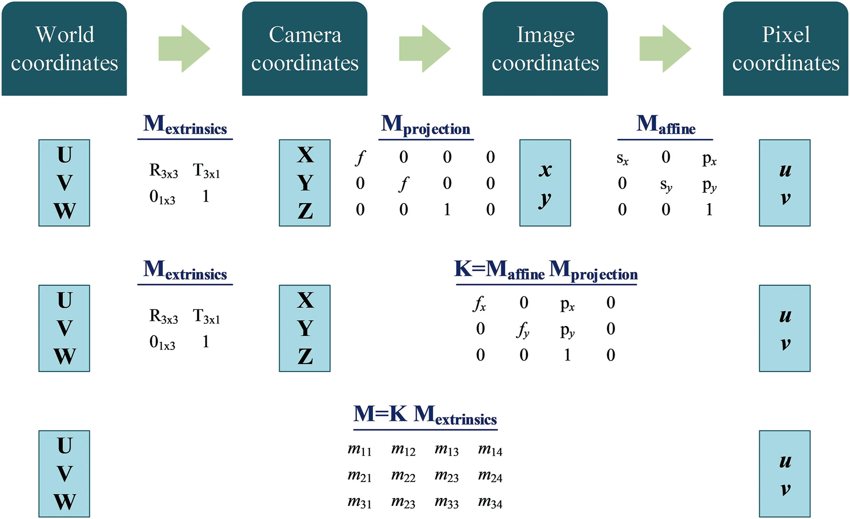
FIGURE 1 Forward projection
Due to the fact that these equations are non-linear,the homogeneous coordinates are utilised.The 2D point is found based on the coordinates(~x,~y,~z)with the use of the equations below.

The projection matrixMprojectionis shown in Figure 1 wherefis the focal length.
The extrinsic parameters are encapsulated inMextrinsics,where R is a 3×3 rotation matrix andTis a 3×1 translation vector.These parameters specify the camera's orientation and position relative to the world frame and are subject to change depending on the world.
Maffineis used to transform(x,y)to pixel coordinates(u,v).The affine transformation takes two factors into consideration;the first one is the scale factor and the second one is the movement of the principal point to the upper left corner.
The intrinsic parameters are specific to each camera,and they are encapsulated in the matrixK.These parameters allow the mapping between the camera coordinates and the pixel coordinates in the image frame.A possible displacement of the centre of the image plane is represented by(px,py)T,physical focal length of the lens multiplied by sxgivesfx,andfyis the product of the physical focal length and syof the pixel.
2.2|Lens distortion
In practice,no lens is perfect.Both main lens distortions are outlined and modelled by Brown [22] and Fryer and Brown[23].Radial distortion is caused by the form of the lens,while the tangential distortion is due to the process of mounting the camera.
The original location of the deformed point is(x,y),and its radial location is determined using the equation below.

wherebeing the new position obtained by the correction.
The tangential distortion is represented by two parameters,p1andp2:

OpenCV bundles the five distortion coefficients to form a 1 × 5 distortion vector in the following order:k1,k2,p1,p2,andk3.
2.3|Epipolar geometry
A basic setup with two cameras taking the image of the same 3D point Q is shown in Figure 2.
The QClCrplane is called the epipolar plane.qland qrare the projection of Q onto the left and the right image planes,respectively.The projection of the different points onforms a line(on the right image plane.This line is called epipolar line corresponding to the point ql.Note that the corresponding point of qlon the right image plane has to be located someplace on this line.In other words,it's not necessary to search the entire image to find the corresponding point,just search along the epipolar line.This is called the epipolar constraint.Likewise,all points have their corresponding epipolar lines in the other image.
Cland Crare the left and the right camera centres,respectively.According to the configuration given by Figure 2,the projection of Cronto the left image plane isel.This point is called the left epipole.In the same way,eris the right epipole.These epipoles are where the image planes intersect with the baseline(ClCr).

FIGURE 2 Epipolar geometry:general case
2.4|Stereo rectification
The issue of identifying the corresponding points can be solved by making the left and right image planes parallel.This process is called image rectification,and it reduces the search area from 2D to 1D.All the epipolar lines lie in the horizontal axe of their images,so the rectification process helps in a major way in simplifying the stereo matching process.It makes the two image planes parallel as shown in Figure 3.

FIGURE 3 Epipolar geometry:parallel stereo

FIGURE 4 Stereo triangulation scheme
2.5|Disparity map
The images obtained from the stereo rectification process are used to create the disparity map.In Figure 4,the distance between the centre of the left camera and the centre of the right camera is B.are the projection of Q onto the left and the right image planes,respectively.Zrepresents the distance from Q to the camera.After the stereo rectification process,we have the sameycoordinates in both images
Using similar triangles,we can write the following equation:

xl-xris what we call disparity;let's put d=xl-xr,and the equation above can be written as follows:


In the Equation (6),fand B have fixed values;the only unknown parameter is d.For this reason,we need to find the disparity,so we can calculate the distance that separates the obstacle from the camera.
3|PROPOSED PROGRAM
Using a seventh generation laptop operating under Windows 10 with an Intel® Core™i7 CPU running at frequencies of 2.70 and 2.90 GHz along with 8 GB of RAM,the proposed Python program is implemented.
Two similar cameras that contain a CMOS(OV2710)and a lens with a focal length of 8 mm are the main components of our stereo vision system.The pattern that contains 10 × 7 corners is used during the calibration.The image resolution is 640 × 480 pixels.In order to imitate human vision,thesecameras are attached to a stiff support.The chessboard is moved and rotated so that the collected images cover the majority of the field of view of the camera.To obtain satisfactory results,a minimum of 10 images of the chessboard are required.Thus,images were captured from a total of 35 different orientations.The flowchart of the proposed program is displayed in Figure 5,and it can be decomposed into four main steps.

FIGURE 5 Flowchart of the proposed program for distance measurement
The detailed process of distance calculation is described as follows:the first step of the process is stereo camera calibration.Each camera is calibrated by finding the position of the corners of the chessboard for the 35 images,and for that,a sub-pixel accuracy corner detection is used.Table 1 shows the retrieved parameters for both cameras.Then,a stereo calibration is applied,and two 3 × 4 projection matrices in the new coordinate system are obtained,PLeftfor the left camera and PRightfor the right camera.The first three columns of PLeftand PRightare the new rectified matrices for each camera.The resulting parameters for the rectified cameras are listed in Table 2.These extracted parameters are used as input data for the next step of the proposed program.
The second step is stereo rectification,where the image pair is projected onto a common image plane.It changes depending on whether it is a calibrated case or not.The first one takes the calibration parameters as entry values;the second one requires corresponding points in the images.As mentioned in the previous section,a rectified image pair has a perfect alignment and all the corresponding lines are parallel to theXaxis of both cameras.In other words,matching points must have the same vertical coordinates,and as a resultthe vertical parallax is eliminated.This is obtained if the new rectified cameras have the same internal parameters,which was the case during this work,as shown in Table 2.After performing stereo camera calibration,the extracted internal and external camera parameters are used during stereo rectification to compute rectification transforms for each calibrated camera.

TABLE 1 Left and right camera parameters
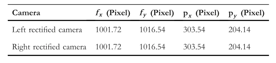
TABLE 2 Parameters of the new rectified left and right matrices
Multiple scenes from different distances are taken by our stereo system.Some of these pairs are displayed in Figure 6.are the original left and right images,respectively.(Lafter)is the left image and(Rafter)is the right image obtained after applying the proposed stereo rectification process.Regarding the obstacle,no observable difference is detected between the pair of images before and after the application of the rectification process,and this is due to the robustness of the support used during this work,and the accuracy of the associated geometry.Notice that there is a slight change in shape between the rectified left and right stereo images.Also,the corresponding points between the left and right rectified images can be located on the same line.
The third step of the proposed program is stereo matching.Before applying the rectification process,the mapping of a point in the left image and its corresponding point in the right image of obstacles is done in 2D(XandYaxes).But after the stereo rectification,it can be done in 1D.Hence,these points have different values only in theXaxis.The proposed stereo matching process implemented in OpenCV is based on SAD(Sum of Absolute Difference) that have the smallest value.It can be decomposed into three steps:
1.Apply pre-filtering in order to normalise the brightness of the image and enhance the texture.
2.Create an SAD window and search for correspondence along horizontal epipolar lines.
3.Apply post-filtering to filter out bad matches.

FIGURE 6 Some pair of images taken from different distances before and after rectification:(a)Obstacle 1,(b)Obstacle 2,(c)Obstacle 3,and(d)Obstacle 4

FIGURE 7 Disparity map post-filtering results for different obstacles
To reduce illumination differences and improve image texture,the input images are normalised in the pre-filtering step.For that,the Contrast Limited Adaptive Histogram Equalisation (CLAHE) is used on the left and right images in greyscale.After that,a power function is utilised to improve the calculation.Next,the search for correspondence is done by sliding the SAD window.For each feature in the left image,a search is done in the corresponding row in the right image to find the best match.The size of the window used during this step is 5×5.Finally,during the post-filtering step,a threshold and a morphological transformation are applied on the disparity map to remove the false positive from the background.Figure 7 displays some image pairs taken during our experiment,and their disparity maps before and after the postfiltering is applied.
The fourth and final step is calculating distance using the disparity maps obtained after stereo matching.
4|EXPERIMENTAL RESULTS AND DISCUSSIONS
Knowing the disparity,the Equation (6) can be used to calculate the distance that separates the obstacle from the camera.More than 80 experiments were performed with different obstacles that were put in front of the stereo vision system.The distances to these objects vary from 60 to 200 cm.The obtained errors are presented in Table 3 whereas the measured distance with respect to the actual distance is displayed in Figure 8.
As shown in these results,the actual values of distance are quite comparable to the ones found during our experiments and the accuracy of distance calculated by our algorithm is higher when the obstacle is close to the cameras.Also within 190 cm the error is below 5%.
Figure 9 displays the variations of measured distance with respect to the disparity.The distance from the obstacle to the camera is inversely proportional to the disparity.Using the real value measured by tape and the distance obtained from our algorithm,the accuracy of the distance value is obtained and compared with similar studies to demonstrate that our proposed algorithm is effective,as shown in Table 4.Theexperimental results obtained during this study show that for obstacles with a distance of 60-200 cm,the average accuracy of 98.19%,compared to the real distance,is reached.The lowest accuracy is 95.19%,and it was found for both 180 and 190 cm while 99.83% is the highest accuracy that was acquired for 100 cm.These results obtained from the comparison validate the proposed method and confirms that our algorithm can calculate distance accurately.

TABLE 3 Error obtained for distance measurement

FIGURE 8 Measured distance with respect to actual distance for the four obstacles

FIGURE 9 Variations of measured distance with respect to the disparity
In the work of Ref.[25],the authors wanted to determine the time needed to have a correct time interval before collision with the obstacle.For that,they first opted to determine the walking speed for visually impaired people.Based on the results presented in some research studies[26,27],the walking speed of a normal pedestrians is 1.22 m/s for young pedestrians,0.91 m/s for the elderly ones,and a visually impaired person's walking speed was supposed to be about 0.6 m/s.Furthermore,the distance to be checked for effective obstacle avoidance had been defined as 2.5 m.
To test the robustness of our algorithm,five tests on each obstacle are performed.Table 5 provides the obtained results for each obstacle.The average time is 0.0586,0.2349,and 0.0611 s for rectifying the pair of images,creating the disparity map,and calculating the distance,respectively.The proposed algorithm needed an average time less than 0.355 s to estimate the distance that exists between the obstacle and the cameras.In other words,during this time the person with visual impairment travelled 0.213 m,which is less than 2.5 m.As a result,the developed algorithm can safely guide people with visual impairments.
Concerning the average processing time.Our work is compared with that of Lai et al.[20];we both used PC system,for the latter,the obtained average accuracy is above 99% for distances ranging from 60 to 120 cm with an averageprocessing time of 0.751 s.While in our case,an average value of 99.35% is obtained for the same distances with an average processing time of 0.355 s.

TABLE 4 Comparison between our algorithm and other studies
5|CONCLUSION
During this work,the principle of the camera model was discussed,and the proposed Python program for stereo camera rectification,feature matching and distance measurement based on the OpenCV library was detailed.Two similar cameras were used to perform real-time experiments.The results showed that our program could generate a stereo-rectified images in a robust manner and within 190 cm,the obtained error was less than 5%,meeting the accuracy needed for the development of applications.This error was due to human error,calibration error and texture.If the obstacle has a low texture,stereo matching process will be affected,and the accuracy of the measurement will be reduced.The average processing time of distance measurement was less than 0.355 s for each pair.The results obtained in this paper will have an important role in our future work,where the system will be combined with other components for obstacle avoidance and moving obstacle detection.In addition,the mobility of this system in two directions will be explored.Furthermore,newcameras with a detection range of about 20 m will be used,and their influence on the accuracy of the measurements will be investigated.

TABLE 5 Processing time
CONFLICT OF INTEREST
The authors declare no conflict of interest.
ORCID
Elmehdi Adilhttps://orcid.org/0000-0003-3780-6326
杂志排行

CAAI Transactions on Intelligence Technology的其它文章
- Matrix‐based method for solving decision domains of neighbourhood multigranulation decision‐theoretic rough sets
- Feature extraction of partial discharge in low‐temperature composite insulation based on VMD‐MSE‐IF
- Wavelet method optimised by ant colony algorithm used for extracting stable and unstable signals in intelligent substations
- Efficient computation of Hash Hirschberg protein alignment utilizing hyper threading multi‐core sharing technology
- Improving sentence simplification model with ordered neurons network
- Demand side management for solving environment constrained economic dispatch of a microgrid system using hybrid MGWOSCACSA algorithm