All polarization-maintaining Er:fiber-based optical frequency comb for frequency comparison of optical clocks
2022-05-16PanZhang张攀YanYanZhang张颜艳MingKunLi李铭坤BingJieRao饶冰洁LuLuYan闫露露FaXiChen陈法喜XiaoFeiZhang张晓斐QunFengChen陈群峰HaiFengJiang姜海峰andShouGangZhang张首刚
Pan Zhang(张攀) Yan-Yan Zhang(张颜艳) Ming-Kun Li(李铭坤) Bing-Jie Rao(饶冰洁)Lu-Lu Yan(闫露露) Fa-Xi Chen(陈法喜) Xiao-Fei Zhang(张晓斐) Qun-Feng Chen(陈群峰)Hai-Feng Jiang(姜海峰) and Shou-Gang Zhang(张首刚)
1National Time Service Center,Chinese Academy of Sciences,Xi’an 710600,China
2University of the Chinese Academy of Sciences,Beijing 100049,China
3Innovation Academy for Precision Measurement Science and Technology,Chinese Academy of Sciences,Wuhan 430071,China
4School of Physics Sciences,University of Science and Technology of China,Hefei 230026,China
Keywords: optical frequency comb,nonlinear amplifying loop mirror,optical clock,frequency instability
1. Introduction
Optical atomic clocks have both relative frequency instability and uncertainty at the 10-18level or even better,[1–6]while state-of-the-art prime Cs fountain clocks have the uncertainty only at the level of 10-16.[7–9]Consequently, optical clocks are considered as candidates to redefine the seconds unit in the International System of Units (SI),[10,11]and the comparisons among at least three different types of optical clocks with uncertainties below 5×10-18have been taken as a mandatory step.[12–14]Recently, NIST and Jila reported a local comparison among optical clocks (Al+, Yb, and Sr)with fractional uncertainties of 8×10-18or less via short free space and optical fibre links. Remote comparison at a similar level on a global scale may require advance satellite-based time and frequency links. Except for metrology applications,comparison clocks with ultra-low instability are also important for others. In comparison with optical clocks at the 10-18level,gravitational potentials can be measured on a centimeter scale on Earth,which provides a precise tool to monitor what happens on Earth and to capture clues about upcoming natural disasters.[15]In the future,more precise clock frequency comparisons may be used to hunt for dark matter and energy and to monitor the cosmos by detecting gravitational waves.[16–18]
Optical frequency comb (OFC) is a kind of unique tool that is used to synthesize optical frequency with unprecedented high stability and accuracy,[19,20]enabling precise frequency comparisons between different optical atomic clocks and application to precise measurements in the optical domain.The inventors of OFCs won a Nobel Prize in 2005.[21,22]In 2004,the optical frequency synthesis and comparison with uncertainty at a 10-19level was achieved with Ti:sapphire-based OFCs,[23]whose stability was good enough compared with that of the best optical clocks at present. Since the instability of an OFC does not limit the results of optical frequency comparisons, the robustness and the flexibility of OFCs become important features. More Er:fiber-based OFCs exhibiting extraordinary robustness have been used for metrology,ranging,time, and frequency transfers.[24,25]The Er:fiber-based OFCs have been obtained based on different mode-locking lasers,such as nonlinear polarization rotation (NPR),[26]a semiconductor saturable absorption mirror(SESAM),[27]and a nonlinear amplifying loop mirror(NALM).[28]In particular,NALM systems have exhibited outstanding robustness and low noise features; consequently, this technique is preferred for applications in scenarios outside the laboratory,[29]and even in space.[30,31]
Optical frequency comparison can be performed by using a single branch supercontinuum generation with a broad optical spectrum covering a few target wavelengths,[32]] but it is difficult to produce enough power simultaneously at all wavelengths. Alternatively,multi-branch architecture can easily produce high power OFC signals at specific wavelengths,making the frequency comparison system more flexible.[33,34]However, this results in more uncompensated fiber paths,which degrades the out-of-loop frequency instability of an OFC. Real-time phase tracking technology can be used to compensate for optical phase drift due to thermal drift,which improves an OFC’s relative instability at a low level of 10-20.[35]However,this technique adds complexity to the optical and electronic measurement system.
In this research, we demonstrate a turnkey erbium fiber laser-based OFC with multi-branch architecture, for which each branch produces a particular wavelength separately at 698 nm, 729 nm, 1068 nm, and 1156 nm, enabling optical beatnotes with a signal-to-noise ratio(SNR)of more than 30 dB at a resolution of 300 kHz.
2. Experiment setup
The schematic diagram of the multi-branch Er:fiber frequency comb is shown in Fig. 1. The multi-branch Er:fiber frequency comb consists of a mode-locked laser(part(a)),fceogeneration and detection(part(b)),four branches for application(part(c)),fbeatdetection and out-of-loop observation(part(d)),and electronic control system(part(e)).
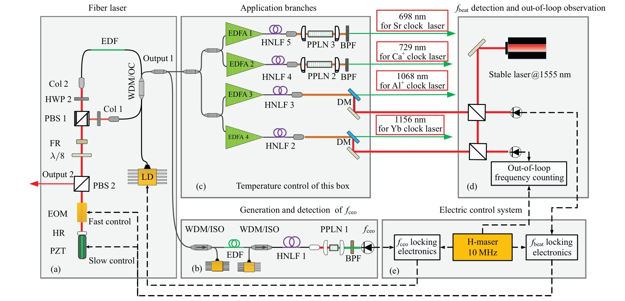
Fig.1. Schematic diagram of five-branch all-PM Er:fiber-based frequency comb and its application to optical clock. Black solid line: single mode PM fiber;black dotted line: electrical signal paths;LD:laser diode;EDF:erbium-doped fiber;WDM:wavelength division multiplexer;ISO:isolator;OC:output coupler;Col: collimator;HWP:half-wavelength plate;PBS:polarization beam splitter;FR:faraday rotator;EOM:electronic optical modulator;PZT: piezoelectric ceramic transducer; HR:high reflector; HNLF: highly nonlinear fiber; EDFA: erbium-doped fiber amplifier; DM: dichroic mirror;BPF:bandpass filter.
2.1. Mode-locked laser
The laser source based on an NALM is composed of a fiber loop and a space linear arm. The optical parts of the laser are housed in a small box which sufficiently decouples the laser from perturbations such as variations of the temperature, humidity, and air pressure. All of the fibers are polarization-maintaining(PM)fibers. The fiber loop consists of a WDM, 40-cm highly erbium-doped fiber (Liekki ER80-4/125),and~50-cm single mode PM fiber. A non-reciprocal phase device,[36]consisting of a Faraday rotator (FR) and aλ/8 wave plate (WP), is installed on the space linear arm to ensure the self-starting operation by introducing a phase bias ofπ/2 between the counter-propagating portions of laser pulses in the fiber loop. A bulk EOM and a PZT are installed in the linear arm for the fast and large-scale control offrep(orfbeat). The net dispersion of the cavity is close to zero when all components and fibers in the cavity are considered.The oscillator automatically starts the mode locking operation when the pump power reaches 900 mW. Figure 2(a) shows the output spectrum of the fiber laser. The full width at half maximum (FWHM) of the spectrum reaches 75 nm at a resolution of 0.1 nm, which is the highest width ever known for this type of mode-locked laser, with a corresponding Fourier transform limit pulse duration of 46 fs. This short pulse duration can effectively reduce the inherent noise of the OFC.Figure 2(b) demonstrates the radio frequency (RF) spectrum of the fiber laser, for which the fundamental repetition rate is up to 200 MHz. The power of 6 mW at the output 1 port is equally distributed to five branches.
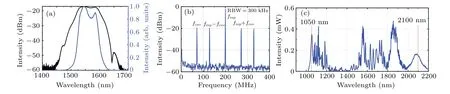
Fig.2. (a)Output spectrum of the mode-locked laser;(b)RF spectrum of repetition rate and fceo beat signal;(c)full octave-spanning SC spectrum.
2.2. Generation and detection of fceo
The branch in part (b) is designed to generate a oneoctave supercontinuum (SC) and detect thefceosignal. The seed laser of the branch is pre-chirped, amplified, and compressed to generate short pulses with an average value of power greater than 200 mW and a pulse duration of about 80 fs. This high-energy femtosecond pulse is injected into a section of PM highly nonlinear optical fiber (HNLF) to produce an SC containing one octave as shown in Fig. 2(c). A standardf-to-2finterferometer following the PM HNLF is used to obtain thefceosignal.The RF spectrum of the detectedfceobeat is shown in Fig. 2(b). The SNR is 38 dB at a resolution bandwidth(RBW)of 300 kHz. This high SNR enables the system to generate a clean feedback signal for controlling the pumping power and stabilizing thefceoat a reference frequency provided by an RF signal generator.
2.3. Supercontinuum generation for optical clock comparison
The other four branches of the OFC, in part (c), are application ports,which compare and measure different types of optical clocks. In detail, the four branches produce signals at wavelengths of 698 nm, 729 nm, 1068 nm, and 1156 nm,which are used for the experiments of Sr, Ca+, Al+(from quadruple 1064 nm), and Yb (from doubled 1156 nm) optical clocks,respectively.
In order to obtain the target wavelengths for optical clock applications,we transfer the optical spectra using the chirped pulse amplification(CPA)technology and the PM highly nonlinear fiber(HNLF).We divide the remaining power(~4 mW)of the OFC into four equal application branches through a two-stage optical coupler. The laser pulse with an average power value of 1 mW is broadened,amplified,and compressed by using CPA technology. Then the laser pulse with a high peak power (about 15 kW) is input into a section of HNLF and its strong nonlinear effect is used to generate the target wavelength. This method can easily generate any wavelengths in a range between 1 μm to 2 μm. For the desired target wavelength to be less than 1 μm or shorter, a frequency doubling crystal is generally used to multiply the fundamental frequency of the target wavelength.
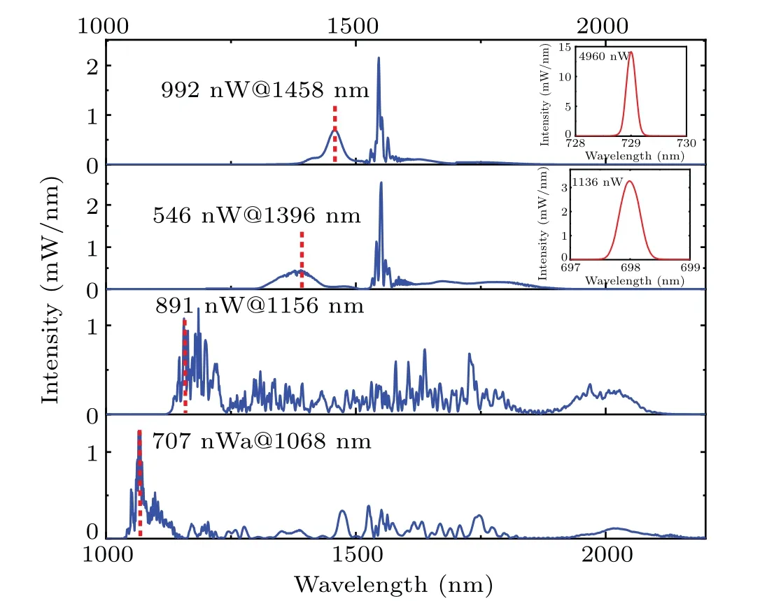
Fig.3. Observed frequency comb spectra of the four branches for different optical clock applications. The spectral wavelengths from bottom to top are 1068 nm, 1156 nm, 1396 nm, and 1458 nm. The insert shows its corresponding spectrum of the PPLN output.
In this experiment, we obtain the target wavelengths of 1068 nm, 1156 nm, 1396 nm, and 1458 nm through the EDFA+HNLF method. The results are shown in Fig. 3. A bulk PPLN crystal is used to obtain the 698-nm and 729-nm wavelengths for Sr and Ca+optical clock applications,as shown in the inset in Fig. 3. For the 1068-nm branch,the first choice is to amplify the 1-mW laser pulse into a more than 200-mW laser pulse through EDFA and to control the length of the PM fiber with negative dispersion to reduce the chirp introduced by the gain fiber with positive dispersion. With this method, the optical pulses with 1.1 nJ in energy and 8.5 kW in peak power can be obtained. Then this high-energy pulse is input into a section of PM-HNLF with a zero-dispersion wavelength(ZDW)of 1545 nm and a dispersion slope of 0.016(ps/nm2)/km at 1550 nm to finally achieve 1068 nm with the single-mode power of 707 nW. Using the same method,a PM-HNLF with a zero-dispersion wavelength of 1405 nm and a dispersion slope of 0.026(ps/nm2)/km,the single-mode power at the target wavelength of 1156 nm is about 891 nW. For the 1458-nm branch, a PM-HNLF with a zero-dispersion wavelength of 1450 nm and a dispersion slope of 0.015(ps/nm2)/km is used to obtain the single-mode power of 992 nW at the target wavelength of 1458 nm.In this branch,we expect to obtain a visible spectrum at 729 nm,which corresponds to the Ca+optical frequency standard wavelength.The extensional comb optical spectrum at 1458 nm is frequencydoubled to 729 nm using a 50-mm bulk PPLN crystal with the temperature sensibility of about 0.3 nm/°C. By using the long PPLN, the single-mode power at the target wavelength can be much higher than that of the pumping laser, while the width of the produced spectrum is narrow, requiring a better temperature control. The single-mode power of 729 nm can reach about 5 μW.By changing the non-linear fiber length and frequency doubling crystal of the 1396-nm branch,we can obtain the target wavelength of 698 nm with a single-mode power value exceeding 1 μW.
Figure 4 shows the beat frequency results of each branch of the optical comb and the corresponding CW laser. It can be seen from the figure that the SNR of each beat signal is greater than 30 dB at an RBW of 300 kHz, which can meet the requirement for the subsequent frequencies for the locking and counting. The noise floors of the beat signal of the 698-nm and 729-nm branches are both 20 dB lower than those of the other branches. This is because the noise of the silicon-based photodetector is smaller than that of the InGaAs photodetector.
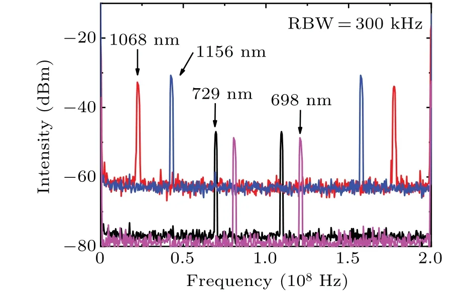
Fig. 4. Optical heterodyne beat signals shown in 300-kHz RBW between the optical spectra shown in Fig.3 and the Sr clock laser at 698 nm in pink,the Ca+ clock laser at 729 nm in black, the Al+ clock at 1068 nm in red,and the Yb clock laser at 1156 nm in blue.
3. Frequency instability of OFC
An OFC can transfer an optical phase between different wavelengths by taking advantage of its frequency control techniques. However, the in-loop and additional frequency instabilities of OFC need evaluating, because this may limit the frequency comparison results.
3.1. Phase locking of fceo and fbeat
Part (e) is the PLL electronic system forfceoandfbeatlocking. The hydrogen maser provides a frequency reference forfceolocking,fbeatlocking, and out-of-loop frequency stability counting. Thefceoandfbeatlocking configurations are described in detail in our previous work.[37]
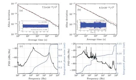
Fig.5. [(a),(b)]In-loop frequency instabilities of stabilized fceo and fbeat,with red dashed line representing the 1/τ1/2 dependence and insets showing the frequency deviation of stabilized signal. [(c),(d)]Phase noise curves of stabilized fceo and fbeat,with black line denoting phase noise power spectral density(PSD),and blue line referring to integrated phase noise.
Figures 5(a) and 5(b) show the Allan deviation (scaled to optical frequencies at 1050 nm forfceoand 1550 nm forfbeat) offceoandfbeat, which are 7.4×10⁻¹⁸/τ1/2and 8.5×10⁻¹⁸/τ1/2for the integration timeτ, respectively. The system’s stabilities meet the regulation withτ-1/2because of the dead time of the counter(Agilent 53230A).The stabilities should improve the inverse proportion to the averaging time if a Π-type counter is used to monitor them.[38]The phase noise offceoandfbeatare shown in Figs.5(c)and 5(d).We choose to focus on the phase noise for offset frequencies between 1 Hz and 1 MHz. The results offceoexhibit integrated phase noise of 0.99 rad from 1 Hz to 1 MHz, and the corresponding time jitter is about 0.55 fs. We also measure thefbeatphase noise curves as shown in Fig.5(d).The corresponding integral phase noise is about 0.14 rad in a frequency range from 1 Hz to 1 MHz,and the time jitter is approximately 0.12 fs. Since the feedback bandwidth (about 300 kHz) offbeatis much larger than that offceo(about 40 kHz), the high frequency part offbeatphase noise is better suppressed,so the phase jitter of thefbeatintegration is less than that offceo.
3.2. Out-of-loop frequency instability
Figure 1(d)shows the process for testing the instability of the out-of-loop. The SC of the 1068-nm branch is divided into a short-wave part containing 1068 nm and a long-wave part containing 1555 nm with a dichroic mirror.The beat signal between the comb and a 1555-nm ultra-stable laser is controlled by the EOM and PZT in the laser cavity through the electronic control system of part(e)to achieve afbeatlock. The 1156-nm branch undergoes the same operation as the 1068-nm branch to obtain the beat signal of the ultra-stable laser. The beat frequency signal is recorded by a frequency counter to achieve out-of-loop instability. Generally,dual OFCs are used for testing the additional frequency stability.[39,40]However, limited by a single OFC and from Ref.[40],it is known that the main factor affecting the frequency instability of fiber OFCs is environmental disturbance in the out-of-loop fiber. Therefore,we can use an OFC system for simple and approximate evaluation. In order to reduce the non-common mode noise between different branches and improve the out-of-loop frequency stability, we adopt a simple and effective method. That is done to ensure that the length and temperature between the different branch fibers are coincident in the reducing non-common mode noise. In this experiment,we ensure that the fiber length error between different branches is within±1 cm,and the temperature control range is within±0.2°C.
The out-of-loop frequency instability of the comb is shown in Fig. 6. The black line in the figure represents the frequency instability of the optical comb locked to the ultrastable laser, and the red line denotes the out-of-loop instability result. The relative instability is 9×10-17at an averaging time of 1 s, and decreases to 5.5×10⁻¹⁹with an averaging time of approximately 4000 s,which is an order of magnitude worse than the counterpart of in-loop instability. We select the comparison results between the most stable Sr and Yb optical clocks in the world,[12]represented by the blue line in Fig.6,for the comparison with our results. It can be seen from Fig.6 that the out-loop stability of our OFC system is better than the result of the optical clock comparison. Therefore,no additional errors will be introduced in the optical clock comparison and measurement.
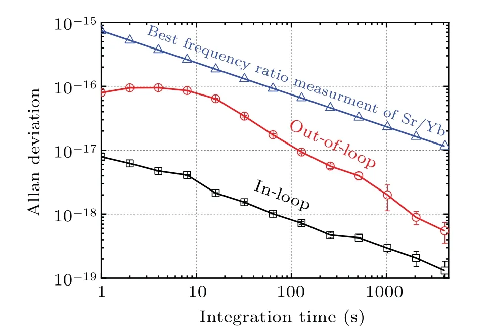
Fig. 6. Allan standard deviation calculated from measured frequencies of the in-loop(black line),out-of-loop(red line),and frequency ratio between the clock transition of Sr and Yb.[11]
4. Conclusions
We demonstrated a turnkey PM Er:fiber laser based on the NALM mode-locking mechanism for the frequency measurement and comparison of Ca+, Al+, Sr, and Yb optical clocks. The laser source exhibits a highly robust feature due to the use of fully PM fibers. The multi-branch approach is used to generate the corresponding comb tooth,which has sufficient power density, enabling optical beatnotes with an SNR of greater than 30 dB for 300-kHz RBW.The in-loop frequency instabilities reach 7.5×10⁻¹⁸/τ1/2and 8.5×10⁻¹⁸/τ1/2. With the careful management of the fiber length and the temperature of each branch,the out-of-loop frequency instability of the OFC is about 9×10-17for 1 s and 5.5×10⁻¹⁹for 4000 s. This homemade OFC system is relatively simple and robust, and its instability is low enough for frequency compensation between optical clocks.
Acknowledgements
Project supported by the Strategic Priority Research Program of the Chinese Academy of Sciences (Grant No. XDB35030101), the National Natural Science Foundation of China(Grant No.61825505),the Quantum Control and Quantum Information of the National Key Research and Development Program of China(Grant No.2020YFA0309800),and the Natural Science Basic Research Program of Shaanxi Province,China(Grant No.2020JQ434).
猜你喜欢
杂志排行

Chinese Physics B的其它文章
- Erratum to“Boundary layer flow and heat transfer of a Casson fluid past a symmetric porous wedge with surface heat flux”
- Erratum to“Accurate GW0 band gaps and their phonon-induced renormalization in solids”
- A novel method for identifying influential nodes in complex networks based on gravity model
- Voter model on adaptive networks
- A novel car-following model by sharing cooperative information transmission delayed effect under V2X environment and its additional energy consumption
- GeSn(0.524 eV)single-junction thermophotovoltaic cells based on the device transport model