Enhancement of electrochemical performance in lithium-ion battery via tantalum oxide coated nickel-rich cathode materials
2022-05-16FenglingChen陈峰岭JiannanLin林建楠YifanChen陈一帆BinbinDong董彬彬ChujunYin尹楚君SiyingTian田飔莹DapengSun孙大鹏JingXie解婧ZhenyuZhang张振宇HongLi李泓andChaoboLi李超波
Fengling Chen(陈峰岭) Jiannan Lin(林建楠) Yifan Chen(陈一帆) Binbin Dong(董彬彬)Chujun Yin(尹楚君) Siying Tian(田飔莹) Dapeng Sun(孙大鹏) Jing Xie(解婧)Zhenyu Zhang(张振宇) Hong Li(李泓) and Chaobo Li(李超波)
1Institute of Microelectronics,Chinese Academy of Sciences,Beiing 100029,China
2University of Chinese Academy of Sciences,Beijing 100049,China
3Institute of Physics,Chinese Academy of Sciences,Beijing 100190,China
4Beijing Welion New Energy Technology Co.,Ltd,Beijing 102402,China
Keywords: LiNi0.88Mn0.03Co0.09O2,tantalum oxide,surface coating,lithium-ion battery,cathode material
1. Introduction
As energy storage devices, lithium-ion batteries are thought to be able to change the traditional energy supply structure by harnessing renewable energy sources. Nowadays, commercialized lithium-ion batteries have been widely applied in the markets of 3C (consumer, computer, and communication), electric tools, and energy storage, which is benefited from their excellent performance, such as high energy density and long cycle life.[1]Among all the components of the lithium-ion battery, cathode material has the highest cost ratio,and it is also one of the important parts that will greatly limit battery performance.[2—8]Cathode material can be divided into three types from the perspective of structure,that is layered, spinel and polyanion originated from Goodenough’s group.[2]And attracted by higher reversible capacity,the layered nickel-rich cathode material (NRM) has been chosen to achieve a longer range for electric vehicles.
The mentioned NRM is generally referred to a polynary derivative of LiNiO2, and in which, Ni ions are partially replaced by other ions (Co, Mn, Al,etc.). And the high reversible capacity of NRM is stemmed from the slight overlaps of Ni3+/4+egand O 2p band.[9]During the charging process, the NRM undergoes a series of phase transitions from the original hexagonal phase (H1), monoclinic (M), another hexagonal phase (H2), and finally to a third hexagonal phase(H3).[10]From the structural perspective, the great change of anisotropic lattice, a and c axis during the H2 and H3 phase transition will cause large volume change,resulting in cathode particle microcracks.[11]The generation of microcracks facilitates electrolyte penetration and cathode particle pulverization,which will further aggravate the degradation of long-term cycle performance.[12]Additionally,the similar ionic radius of Ni2+(0.69 °A)and Li+(0.76 °A),as well as the magnetic frustration of Jahn—Teller active Ni3+(t62ge1g) has been believed to be the main culprit of cation mixing.[11,13,14]These factors contribute to voltage decay and capacity fading at the cathode level, especially under high temperatures.[15]Nevertheless, the surface deterioration of NRM is normally attributed to the presence of a large amount of Ni ions with high valance(Ni3+and Ni4+), which has high oxidation activity and will further interact with moisture in the air during storage and electrolyte in delithiation state.[16]It is worth noting that all those factors interplay with each other and contribute to the failure of NRM.
A number of improved methods acted on the cathode material bulk and surface has been developed to mitigate these degradation issues of NRM,such as bulk/surface doping,surface coating, single crystal, heterostructure, and concentration gradient design.[15,17,18]Among the aforementioned strategies,surface modification is one of the most straightforward approaches. The surface state of the cathode material is closely related to many undesired reactions, which further lead to surface reconstruction,formation of the resistive layer,and transition metal desolution.[19]And a reasonable cathode—electrolyte interface has a decisive impact on the overall efficiency of the batteries. Therefore,the surface design of cathode material is very necessary. Recently, tantalum has been found to be a very useful element for bulk/surface doping and surface coating of cathode material.[20—22]And according to the research results, tantalum possesses the strongest binding energy with oxygen (839 kJ/mol), which can inhibit oxygen release during lithium extraction.[23]The similar radius of Ta5+(0.64 °A) with Ni2+(0.69 °A) can promote the occupation of lithium site instead,[24]and Ta5+with higher valance in lithium sites can also compensate for the charge variation during lithium migration via screening oxygen ion repulsion.[24,25]Whereas there are few studies about surface coating by tantalum element,and further investigation is needed. In this work, the electrochemical performance of LiNi0.88Mn0.03Co0.09O2(NMC)was well improved via functional surface modification of tantalum oxide,and the reasons were also studied.
2. Experimental details
2.1. Materials
The NMC powder was made by Beijing Welion New Energy Technology Company Limited. The detailed preparation process was described in supporting information.A wet chemical method was chosen to perform the coating process.An optimized amount of tantalum ethoxide (Ta(C2H5O)5, 99.99%,Aladdin) was firstly dissolved into ethanol and then NMC powder was added under stirring, and after the ethanol evaporated in oil bath followed by further heating at 120°C for 30 min, the coated LiNi0.88Mn0.03Co0.09O2(C-NMC) power was obtained. The C-NMC powder was further annealed at 550°C for 12 hours in an oxygen atmosphere to get the final sample, that is CA-NMC powder. The mass fraction of tantalum elements in CA-NMC is 0.4%. Additionally, the bare NMC (B-NMC) powder was prepared by the same process without adding tantalum ethoxide. All the above powder was stored in a vacuum. The coating amount is optimized in advance(0.1%,0.2%,0.3%,0.4%,and 0.5%)and choose 0.4%as research target due to its superior overall performance.
2.2. Coin cell assembling
To prepare the positive electrode,firstly,the cathode materials(B-NMC,C-NMC,and CA-NMC),carbon black(super P,Timcal)and polyvinylidenefluoride(PVDF,Sovlay Group)with a weight ratio of 90:5:5 were dispersed in N-methyl pyrrolidone(NMP,MYJ Chemical Co.,Ltd.)solvent,and then the resulting slurry was coated on aluminum foil followed by drying at 120°C for~12 hours in a vacuum oven. The test cells were assembled into CR2032 coin-type cells in an argonfilled glove box,with Li foil as the anode and Celgard 3501 as the separator.The electrode diameter was 12 mm and the cathode material load was around 12.0 mg/cm2. The amount of electrolyte(1-M LiPF6 dissolved in EC/DEC/EMC with volume ratio=1:1:1) used in each coin cell was 90 μL. All the cells were placed for 6 hours before the test to ensure sufficient infiltration of the electrolyte.
2.3. Electrochemical test
All the cells were activated at 0.1 C (1 C=220 mAh/g)for two cycles before the subsequent cycle(1 C/1 C)and rate(0.1 C/0.1 C,0.2 C/0.2 C,0.5 C/0.5 C,1 C/1 C,5 C/5 C,and 0.1 C/0.1 C)tests,and those electrochemical tests were carried out using galvanostatic charge/discharge method (LANHE,CT2001A) between 3.0 V—4.4 V (versusLi/Li+) at 25°C or 45°C. Cyclic voltammetry (CV) tests were performed on an RST 5200F electrochemical workstation at a scan rate of 0.1 mV and a voltage range of 3.0 V—4.4 V. Electrochemical impedance spectroscopy (EIS) was conducted on an RST 5200F electrochemical workstation with a voltage amplitude of 5 mV and frequency range of 0.1 Hz—106Hz.
2.4. Characterization
The cathode materials were measured by powder xray diffraction (XRD, Brucker D8 Advanced) to identify the sample phase. The sample morphology and microstructure were acquired on scanning electron microscopy(SEM,Hitach SU8200) and transmission electron spectroscopy (TEM, FEI Talos F200X). Besides, energy dispersive x-ray spectroscopy(EDS) mapping was implemented by using EDS equipment connected to SEM. X-ray photoelectron spectroscopy (XPS,Thermo escalab 250Xi)analysis was conducted to investigate the valance state of the main element composition on the surface of materials. The cross-section of cycled electrodes was prepared by an ion milling machine(Gatan 691). DSC(differential scanning calorimetry, Jupiter Netzsch) was performed from 25°C to 500°C at a heating rate of 5°C/min under a nitrogen atmosphere.
3. Results and discussion
3.1. Morphology and structure
The SEM images of NMC materials before and after coating are shown in Figs.1(a)—1(c). The spherical cathode aggregates are composed of primary particles below 400 nm, and the aggregates remain intact after the wet chemical treatment and calcination process. And according to the inset images of higher magnification,there is no apparent difference within the surface of NMC samples before and after coating, indicating that the coating or annealing process induces a minimal change in the morphology. The EDS mapping images(Fig. 1(d)) present the existence and uniform distribution of Ta element in the CA-NMC sample, which means that the modification of tantalum oxide is believable and successful.High-resolution transmission electron microscopy (HRTEM)and fast Fourier transform(FFT)measurements were utilized to estimate the coating thickness and the surface structure change after coating or heat treatment,and the results are displayed in Figs.1(e)—1(g). The coating layer with a thickness of~8 nm on the surface of the C-NMC sample can be observed in Fig.1(e),and it is decreased to~6 nm after calcination treatment(Fig.1(f)). However,the surface of the B-NMC sample shows a smooth edge without any coatings(Fig.1(g)).Meanwhile, it can be seen that all these three samples possess a layered structure near the surface. The crystal faces of(006),(113),(104),(107),(101)are well-identified in the FFT patterns of the three samples, which implies that the coating or calcination process does not change the hexagonal layered crystalline structure of the NMC materials.[22,26]All the above results demonstrate that the surface structure is retained and consistent with the bulk after surface coating of tantalum oxide.
As shown in Fig.2(a),the XRD patterns of C-NMC,CANMC,and B-NMC indicate that all the cathode samples have a hexagonalα-NaFeO2structure with good crystallinity (R-3mspace group, PDF#97-016-9367). Arising from the low amount of coating materials,the diffraction peaks of tantalum oxide is absent in C-NMC and CA-NMC sample (Figs. 2(a)and 2(b)). The typical (003) peak of C-NMC and CA-NMC slightly shift to a lower degree in comparison with B-NMC(Fig. 2(b)). The slight shift cannot exactly indicate the increase ofcaxis and surface doping of coating materials. And the XRD fitting results are summarized in Table 1,in which the Rwp represent overall error in fitting. Moreover, all of thea,caxis and the volume increase after coating,which may stem from the larger ionic radius of Ta5+(0.64 °A)compared to Ni3+(0.56 °A).[27]All three samples exhibit good layered structure and a low degree of cation mixing,confirmed by the value of peak intensity ratio (I003/I104>1.2) andc/a(>4.9).[28,29]The distinct splitting of (006)/(012) and (108)/(110) peaks point out that the materials have a good hexagonal structure(Figs.2(c)and 2(d)).[30]It can be seen that the introduction of tantalum oxide has no bad effect on the layered nature of the bulk phase.
To study the influence of coated tantalum oxide on the elemental states of the materials,XPS measurements were conducted and the results are displayed in Figs. 2(e)—2(g). The major peaks of the Ni element can be found in the whole spectra(Fig.2(e)),and figure 2(f)illustrates that the Ni 2p3/2peak is consisted of Ni2+and Ni3+with different proportions,locating at 854.9 eV and 856.0 eV respectively.[31]The Ni 2p3/2peak of B-NMC at 855.98 eV is shifted to the higher binding energy of 856.04 eV for CA-NMC, which is due to the increase of valance state.[32]After the calculation of peak area,the area ratios of the Ni2+/Ni3+are 0.99,0.68,and 1.27 for C-NMC, CA-NMC, and B-NMC respectively. The lower value of the Ni2+/Ni3+ratio means the lower level of cation mixing,[22]and the increased amount of Ni3+on the surface of CA-NMC is mainly owing to the charge compensation mechanism of Ta5+,which is beneficial for the cation ordering and the electrochemical activity of the Ni-rich cathode.[22]Additionally,it is also believed that the coating layer could stabilize the surface of the CA-NMC sample,allowing more Ni3+to be retained. The XPS peaks in Fig. 2(g) prove the existence of Ta5+in CA-NMC.[33—35]
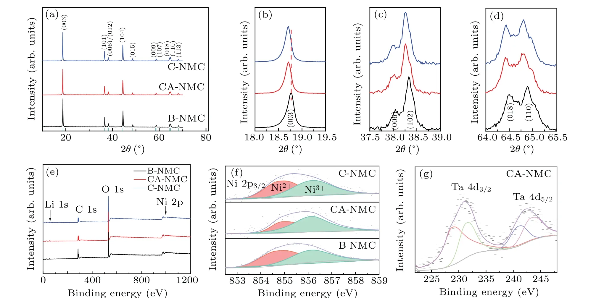
Fig.2. XRD patterns of(a)C-NMC,CA-NMC,and B-NMC.(b)—(d)Magnified view of(003)peak(b),(006)/(012)peaks(c),and(018)/(110)peaks(d). XPS results for(e)survey scan,(f)Ni 2p3/2,and(g)Ta 4d CA-NMC.
3.2. Room temperature test
Electrochemical tests were carried out at room temperature to investigate the effects of surface modification. Figure 3(a) shows the charge—discharge profiles of C-NMC, BNMC,and CA-NMC samples at 0.1 C(1 C=220 mAh/g)with a voltage range of 3.0 V—4.4 V.No new platform is found after the coating of tantalum oxide,but the initial discharge capacity of C-NMC sample (217 mAh/g) is significantly lower than that of the other two samples(B-NMC:224 mAh/g;CANMC: 225 mAh/g). Meanwhile, the initial coulombic efficiencies of the C-NMC, B-NMC, and CA-NMC samples are~91%,~93%, and~93% respectively. After 150 cycles at 1 C,the CA-NMC sample shows the highest capacity retention of 83%,and the cycle performance of C-NMC is the poorest,as presented in Fig.3(b). And according to the results of rate capability, a similar conclusion can be drawn(Fig.3(c)).The reason for the superior performance of the CA-NMC sample might be that a beneficial and protective coating layer is formed via the coating process with further annealing, which can not only reduce the side reaction between the cathode material surface and electrolyte,but also will not hinder the surface transport of Li+. Although the surface modification is performed for the C-NMC sample,a coating layer without calcination may lead to slow Li+diffusion kinetics. Actually,the annealing treatment is a process that can repair the surface damage caused by the wet chemical coating method and also make the coating layer tighter,which will generate an interface with Li+transport activity. For the uncoated B-NMC sample,where there is no protective layer on the surface,poor performance is reasonable.
The curves of differential capacity as a function of voltage are shown in Figs. 3(d)—3(f), containing several redox peaks.The nature of the redox species is concerned with the Ni2+/4+and Co3+/4+oxidation/reduction process accompanied with phase transition(hexagonal(H1),monoclinic(M),hexagonal(H2), hexagonal (H3)).[36]With the increased cycling number, the peak height at~3.7 V decreases, standing for a kinetic hindrance to Li+diffusion and loss of reversible capacity originated from structural damage.[37]For C-NMC,the H1—M peak heights decrease from 785 mAh/gV to 398 mAh/gV after 100 cycles corresponding to 49% height loss. This value is smaller for CA-NMC(43%)and B-NMC(48%). Moreover,a more pronounced peak shift is observed in C-NMC and BNMC samples, especially at the start of discharge (H3—H2),which indicates greater impedance growth during a prolonged cycle.[38]The C-NMC shifted 0.1 V to lower voltage,which is larger than CA-NMC(0.06 V)and B-NMC(0.06 V).The shift to higher polarization can be attributed to higher overpotentials for Li+intercalation/extraction into/from the host lattice.[39]A progressively increasing charge transfer resistance is a possible explanation for this observation and it will be further studied by subsequent EIS measurement.
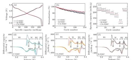
Fig. 3. Initial charge—discharge profiles at 0.1 C (a), cycling performance of 150 cycles at 1 C (b), rate capability (c) of C-NMC, B-NMC, and CA-NMC,dQ/dV profiles obtained by differentiating charge—discharge curves of every 25 cycles of C-NMC(d),CA-NMC(e),and B-NMC(f). All the measurements were tested under a voltage range of 3.0 V—4.4 V at room temperature.
3.3. High temperature test
High temperature tests at 45°C were also performed to study the electrochemical performance,as presented in Fig.4.Compared to the room temperature performance, the three samples exhibit higher initial discharge capacities (B-NMC:229 mAh/g; C-NMC: 229 mAh/g; CA-NMC: 233 mAh/g)and initial coulombic efficiencies (~95% of all) and lower potential polarization (Fig. 4(a)). It is worth noting that the CA-NMC sample can bring out the highest capacity, and as expected, the best cycle performance is found for the CANMC sample (Fig. 4(b)). The initial capacity is even parallel to those Ni90 or Ni95 cathode.[31,40]With the increase of cycling number, the voltage decay is noticeable for C-NMC and B-NMC samples,which is much slower for the CA-NMC sample (Figs. 4(c)—4(e)). As is well known, the voltage decay for cathode material is partly attributed to element dissolution and structure degradation, and surface coating is a very helpful strategy due to the formation of a protective layer,which is proved by the above results. The NRM suffers from the generation of microcracks, and the cross-sectional SEM images of B-NMC and CA-NMC samples after 150 cycles(Fig. S1 in supporting information) show that a stable coating layer is beneficial to reduce the risk of microcrack formation and the further side reaction and structure degradation,that means of the surface stability is very important for NRM.The allevation of microcrack formation is may be related to the buffering effect of coating layer and accommodation of internal stress.[41]The dQ/dVprofiles of the three samples obtained at 45°C exhibits a similar result with the room temperature test,as displayed in Figs.4(f)—4(h). Higher peak shift and polarization are observed for B-NMC and C-NMC samples,and the modified one is more stable. More specifically, the peak around 4.2 V during charging process decrease 76%and 70% for C-NMC and B-NMC after 100 cycles respectively,whereas, the CA-NMC sample presents moderate height loss of 59%. Meanwhile, the H3—H2 peak shifted 0.12 V for CNMC and B-NMC after 100 cycles,which is larger than CANMC(0.07 V).What is more,the plots of the average voltageversuscycle number illuminate a smaller voltage hysteresis of 0.18 V for the CA-NMC sample(Fig.S2 in supporting information), and the better thermal stability of the CA-NMC sample is confirmed by the DSC curves in Fig.S3 in supporting information. According to the results of room and high temperature tests, it can be concluded that surface coating of tantalum oxide is a useful way to improve the electrochemical performance of NRM.To gain a better understanding of the coating layer on electrochemical polarization during the charge/discharge process,the CV profiles of C-NMC,CA-NMC,and B-NMC samples for the initial three cycles at a scanning rate of 0.1 mV/s between 3.0 V—4.4 V are presented in Fig. 5. Several anodic peaks (oxidation) and cathodic peaks (reduction) resulting from multiple phase change with Li+extraction and insertion process consist in the CV curves. The potential gaps between the redox peaks of the CA-NMC sample marked in the CV profiles are narrower than that of both B-NMC and C-NMC samples, indicating that the polarization becomes smaller via functional coating of tantalum oxide,and the results are summarized in Table 2.

Fig.4. Initial charge—discharge profiles at 0.1 C(a),cycling performance of 150 cycles at 1 C(b)of C-NMC,B-NMC,and CA-NMC;voltage-discharge capacity curves at different cycle[(c)—(e)]and dQ/dV profiles obtained by differentiating charge-discharge curves of every 25 cycle for C-NMC[(c)and(f)],CA-NMC[(d)and(g)]and B-NMC[(e)and(h)]. All the measurements were tested under a voltage range of 3.0 V—4.4 V at 45 °C.
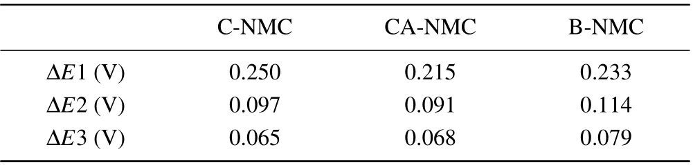
Table 2. The potential gaps between the first anodic and cathodic peaks marked in Fig.5.
Electrochemical impedance spectroscopy was employed to offer insight into the resistance evolution for the three samples at a frequency ranging from 106Hz to 0.1 Hz after different charge/discharge numbers (Figs. 5(d)—5(f)).Z-view software is used to fit the impedance of the electrode and the simulated impedance parameters are listed in Table S1. The simulated circuit is presented in inset of Fig. 5(d). Two semicircles at the high and middle-frequency regions are consisted in each spectrum, and the semicircle at high frequency is related to the resistance of CEI(cathode electrolyte interphase)film on the surface,without a noticeable change in the whole cycling range. The C-NMC and B-NMC samples exhibit a larger radius for the semicircle at middle frequency, and the radius notably increases with the cycle number,implying that the charge transfer resistance is larger and the growth is more significant after the cycle. This may be the consequence of electrolyte consumption and accumulation of poorly conductive by-products, which hinder the fast transport of Li+.[42]However,the CA-NMC sample shows smaller charge transfer resistance and suppressed impedance growth, suggesting that the coating layer of tantalum oxide with further calcination is very stable and helpful in providing and maintaining fast charge transfer kinetics for NRM upon repeated cycle. Besides,the CA-NMC sample exhibits a larger initial Li+diffusion coefficient(D+Li),and the decrease of D+Liafter 150 cycles is insignificant compared with that of the other two samples(Table S1,supporting information).The higher D+Liof the CANMC sample is also responsible for its good electrochemical performance. The calculation process is presented in supporting information(Fig.S4,supporting information).
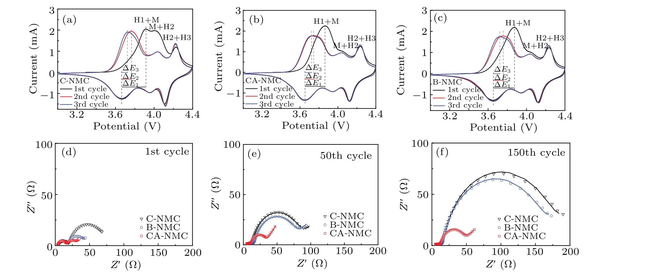
Fig.5. Cyclic voltammograms of C-NMC(a),CA-NMC(b),and B-NMC(c)for initial three cycles between 3.0 V—4.4 V at a scanning rate of 0.1 mV/s.Nyquist plots of the first cycle(d),the 50th cycle(e),and 150th cycle(f)at charged state.
In view of the great importance of CEI film on the electrochemical behavior of cathode materials, it is necessary to explore the chemical composition of CEI film generated on the surface of cycled samples with or without tantalum oxide coating. Therefore,the electrodes with different samples after 150 cycles at 45°C were disassembled and measured by XPS,and the results reveal that the CEI layer is mainly composed of C—O, C=O, C—F, and LiF as the decomposition products of electrolytes (Fig. 6). In the C 1s spectra (Fig. 6(a)), the peaks located at 284.8 eV correspond to the acetylene black,while the peak located at 290.8 eV is assigned to the CF2group from PVDF.[43]The peaks at 286.1 eV and 289.1 eV are associated with the C—O and C=O.[42,44]In Fig. 6(b),the O 1s spectra indicate the presence of C—O (531.7 eV)and C=O (533.1 eV).[42,43,46]And these species can be attributed to the decomposition of the carbonate electrolyte,leading to the formation of organic lithium alkyl carbonates(ROCO2Li) and lithium carbonates (Li2CO3). The tantalum oxide layer could partly reduce the electrolyte decomposition as seen from the proportion of surface chemical composition in Fig. 6(d). Compared to the B-NMC sample, CA-NMC possesses fewer organic components and a large proportion of inorganic Li—F. This may be originated from the formation of more beneficial electrolyte decomposition products LiF(685.03 eV) on the CA-NMC sample (Fig. 6(c)).[43,47]It has been reported that the LiF film is Li+conductive and can act as HF scavenger.[48,49]Overall,there are more by-products of electrolyte decomposition for B-NMC,and it implies that tantalum oxide modification could provide effective protection from side reactions.
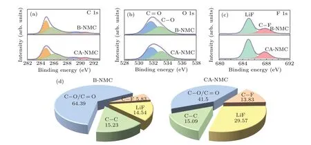
Fig.6. XPS spectra of(a)C 1s,(b)O 1s,and(c)F 1s. (d)The substance concentration for B-NMC and CA-NMC after 150 cycles at 45 °C between 3.0 V—4.4 V at 1 C.
4. Conclusion and perspectives
In the present study, ultrathin tantalum oxide coated LiNi0.88Mn0.03Co0.09O2cathode material was successfully prepared via wet chemical method followed by annealing treatment, and the structural characteristics and electrochemical performance were investigated. With the functional modification of tantalum oxide, the surface stability of LiNi0.88Mn0.03Co0.09O2is enhanced without hindering Li+transport and diffusion, and the side reaction with electrolyte is also suppressed. Furthermore, the capacity, rate and cycle performance are found to be improved along with low polarization and voltage decay. It is worth noting that the further calcination treatment is favorable for the formation of a tight coating layer and fast Li+transport interface. These findings of this study provide a beneficial and practical approach to protect the surface of nickel-rich cathode materials,which offers helpful insight for the optimization of cathode materials in the industry.
Acknowledgements
Zhenyu Zhang, Hong Li and Chaobo Li conceived and directed the project. Fengling Chen performed synthesis,performance testing and characterization. Jiannan Lin, Yifan Chen and Binbin Dong assisted the synthesis. Siying Tian,Dapeng Sun,Jing Xie and Chujun Yin collected and analyzed the XRD, SEM, and TEM data. Fengling Chen wrote the manuscript with assistance from all the authors.
Project supported by the Key Laboratory Fund (Grant No.6142804200303)from Science and Technology on Microsystem Laboratory,the Key Research Program of Frontier Sciences of the Chinese Academy of Sciences: Original Innovation Projects from 0 to 1 (Grant No. ZDBS-LY-JSC010), the Key Research and Development Project of the Department of Science and Technology of Jiangsu Province, China (Grant No. BE2020003), the Beijing Municipal Science and Technology Commission(Grant No.Z191100004719001),and the National Key Research and Development Program of China(Grant No.2017YFB0405400).
猜你喜欢
杂志排行

Chinese Physics B的其它文章
- Erratum to“Boundary layer flow and heat transfer of a Casson fluid past a symmetric porous wedge with surface heat flux”
- Erratum to“Accurate GW0 band gaps and their phonon-induced renormalization in solids”
- A novel method for identifying influential nodes in complex networks based on gravity model
- Voter model on adaptive networks
- A novel car-following model by sharing cooperative information transmission delayed effect under V2X environment and its additional energy consumption
- GeSn(0.524 eV)single-junction thermophotovoltaic cells based on the device transport model