Eccentric actuator driven by stacked electrohydrodynamic pumps
2022-05-10ZebingMAOYotaASAIArdiWIRANATADeqingKONGJiaMAN
Ze-bing MAO ,Yota ASAI ,Ardi WIRANATA,2 ,De-qing KONG ,Jia MAN
1Smart Materials Lab,Department of Engineering Science and Mechanics,Shibaura Institute of Technology,Tokyo 135-8548,Japan
2Department of Mechanical and Industrial Engineering,Faculty of Engineering,University of Gadjah Mada,Yogyakarta 55281,Indonesia 3Muroran Institute of Technology,Muroran,Hokkaido,Japan
4Key Laboratory of High Efficiency and Clean Mechanical Manufacture of MOE,School of Mechanical Engineering,Shandong University,Jinan 250061,China
1 Introduction
In the last decades,many fluidic actuators have been developed for numerous applications,e.g.,artificial muscles (Wang and Qu,2016),soft spatial finger(Mao et al.,2020a,2020c),soft robots(Shepherd et al.,2011),and compliant gripper (Li et al.,2021).Differing in their dimensions,they can be categorized into two groups:piston-cylinder fluidic actuators and elastic fluidic actuators (de Volder and Reynaerts,2010;Ye et al.,2019).Piston-cylinder actuators (Xu et al.,2015b;Zhang et al.,2018) can generate long strokes and high actuation forces,and are usually large.In these actuators,the piston should slide freely and switch its direction by adjusting the pressurized chamber.However,they are difficult to make due to the need for low friction sealing.To overcome that problem,some sealing methods,including hermetic seals(Wapner and Hoffman,2002)and O-rings(Peirs et al.,2001;Xu et al.,2015a),have been developed to enhance the performance of the piston-cylinder fluidic actuators.Also,the working pressure of the pistoncylinder fluidic actuators is very high,reaching over 1.0 MPa (Xu et al.,2016;Cheng et al.,2021;Ding et al.,2021),and the system,having piston-cylinder fluidic actuators,is very complex,needing external hydraulic pumps,air compressors,and solenoid valves.Challenges for fluidic actuators include the realization of a simple fabrication process and easy operation.For soft actuators,there is a well-known method entitled the do-it-yourself (DIY) approach (Murakami et al.,2021;Wiranata and Maeda,2021;Wiranata et al.,2021a,2021b).This method offers a novel opportunity for a researcher to customize and operate soft actuators easily.For fluidic actuators,such a DIY strategy can stimulate and accelerate the growth of innovation.Much effort has been devoted to realizing a simple fabrication process and easy operation for fluidic actuators.
To obtain a simple fabrication process and easy operation,many researchers have proposed elastic fluidic actuators without internal moving parts,which are also compatible with standard soft lithography.These elastic fluidic actuators include bellows (Sun et al.,2020),balloons (Jung and Rodrigue,2019),artificial muscle (Kim et al.,2021;Kong et al.,2021),and membrane (Sinatra et al.,2018) based on a variety of implementations.Most of these actuators are actuated by pneumatic systems and external small pumps,which call for larger power sources such as bulky air compressors and solenoid valves.Considering the total system,these robot fingers or hands incorporating external pneumatic power sources are heavy and cumbersome.Consequently,there is a need to develop a more suitable driving source.
To overcome the problems mentioned,we focused on electrohydrodynamic (EHD) pumps,which use a kind of dielectric and functional fluid.These fluids can generate flow under high applied voltages.Unlike gel pumps(Mao et al.,2020b,2021b;Yoshimura et al.,2020),soft EHD pumps can be used as the power source of the actuators and microfluidics,such as fan(Seki et al.,2020),soft finger (Cacucciolo et al.,2019;Mao et al.,2021a),McKibben muscles(Cacucciolo et al.,2020),and droplet generators and sorters based on the electro-conjugate fluid (ECF) (Mao et al.,2019a,2019b,2019c).However,in the applications described,they generate little pressure and flow rate,which has limited their applications in soft robots.To increase the output power of EHD pumps,we propose a stacked EHD pump with a simple pattern of copper electrodes.The EHD pump is bendable and twistable because of the flexible materials of its cover and base as shown in Fig.1.We then investigate the performance of a single EHD pump and of stacked EHD pumps,and finally apply them to a soft eccentric actuator.
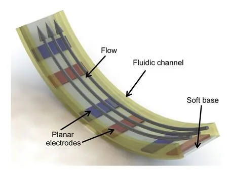
Fig.1 Schematic diagram of EHD pump(bending state)
2 Design,liquid,and manufacture
2.1 Design and liquids
Hydrofluoroethers (HFEs) are often used as the medium for EHD pumps,such as HFE 7300 (3M™Novec™Engineered Fluids,USA),because they have high thermal and chemical stability.By using such fluids,we can generate EHD flow under a high applied voltage.In previous work (Darabi et al.,2002),sawtooth electrodes have been shown to generate a high flow rate and pressure.Here,we adopted that type of EHD electrode to our design (Fig.2).In one EHD pump,we designed nine pairs of sawtooth and planar electrodes (Fig.2a).Briefly,both the base and cover were made of polypropylene (PP) sheets;the electrodes consisted of copper;the fluidic channel was formed by PP sheets (500 μm in thick) (Fig.2b).To increase the output pressure and flow rate,we stacked four small EHD pumps into one large pump(Fig.2c).The total sizes of the stacked pumps are 113 mm in length,20 mm in width,and 3 mm in height.
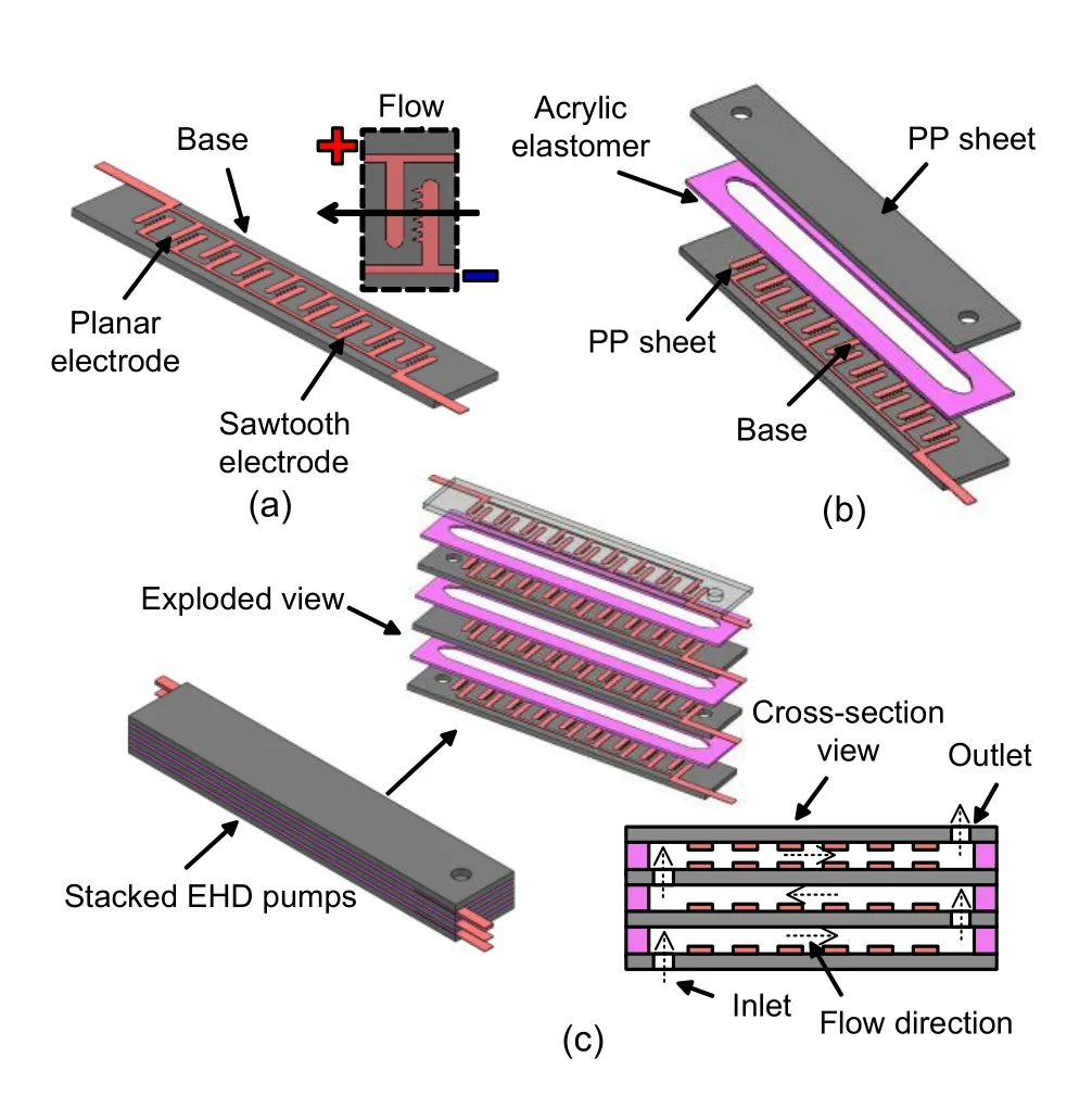
Fig.2 Schematics of single and stacked EHD pumps:(a) design of electrodes;(b) one unit of EHD pumps;(c)stacked EHD pumps
2.2 Manufacture
In the fabrication process,we cleaned the PP sheets with acetone(Fig.3a)and then adhered a layer of copper to them(Fig.3b).A cutting plotter,namely,GRAPHTEC CE6000-40 Plus,was used to decide the electrode pattern (Fig.3c).We separated each EHD pump and made a hole using a laser cutter (Trotec Speedy 100,Trotec Laser Inc.,Austria).After preparing a fluidic channel(500-μm thick),we attached it to the EHD pump (Fig.3e).Next,we fabricated four EHD pumps and stacked them together (Fig.3f).The stacked pump was completed as shown in Fig.3g.The eccentric actuator was built as follows.We prepared molds using the 3D printer(Agilista-3200,Keyence,Japan),in which acryl resin (AR-M2,Keyence)and hydrosoluble acryl resin (AR-S1,Keyence) were used as the main and support materials,respectively(Fig.3h).Then,silicone liquids(Ecoflex 30,Smooth-On,USA) were poured into the eccentric tube actuator.The eccentric actuator was formed and sealed by a cap(Figs.3i and 3j).After cross-linking,we obtained an eccentric actuator (45 mm in length),3D-printed the adaptor,and assembled it to the stacked EHD pumps(Figs.3k and 3l).
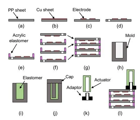
Fig.3 Fabrication process of EHD pumps and eccentric actuator:(a) preparing PP sheet;(b) attaching copper layer;(c) patterning electrode layers;(d) removing unnecessary parts;(e)adhering fluidic channel;(f)bonding process;(g) completing bonding;(h) preparing molds;(i)pouring silicone liquid;(j) sealing the mold;(k) removing and assembling;(l)final assembly
3 Results
3.1 Single EHD pump
The bendable and twistable EHD pump is shown in Fig.4.The output pressure and flow rate of the EHD pump with one layer of copper electrodes were then investigated (Fig.5).We used the Tygon tubes(LMT-55)with their inner diameter of 2 mm and outer diameter of 4 mm,respectively,to connect the EHD pumps and EHD tank.The bubbles in the EHD pumps were removed by a vacuum system.The pressure was obtained by the equation:p
=ρgh
,whereρ
,g
,andh
are the density of the liquid,the gravitational acceleration,and the measured height,respectively.In our case,the direct current (DC) voltage was provided by Matsusada Precision Inc.,Japan.The flow rate was calculated by dividing the mass reduction over time.In Fig.5,it is shown that both the flow rate and the pressure of EHD pumps increase with the growth of the applied voltage.The maximum values of pressure and flow rate of this EHD pump were 3.2 kPa and 24.09 mL/min,respectively.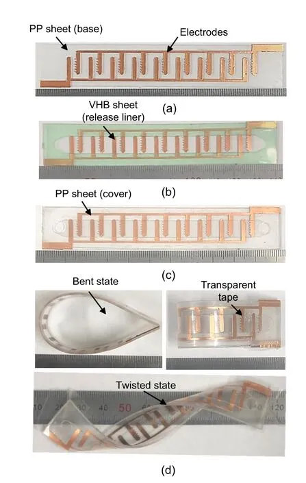
Fig.4 Optical images of one layer of EHD pump:(a) PP sheet and Cu electrodes;(b) addition of very high bond(VHB) sheet (release liner included);(c) bonded EHD pump;(d)bent and twisted states of EHD pumps
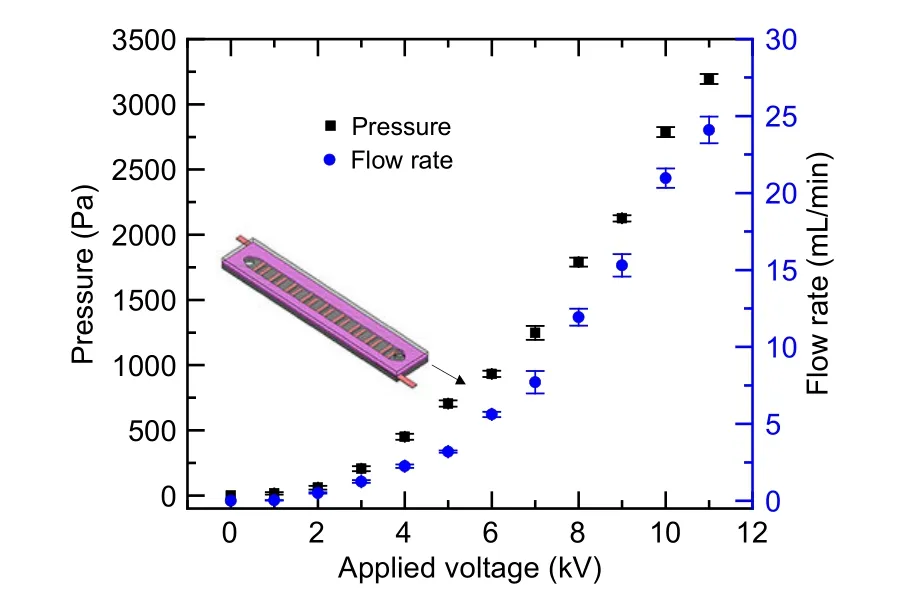
Fig.5 Performance of one layer of EHD pumps in terms of generated pressure and flow rate
3.2 Stacked EHD pumps
Here,we verified the performance of stacked pumps regarding generated pressure and flow rates as shown in Fig.6a.The pressure and flow rates increase as the applied voltages increase.In our case,the generated pressure and flow rates achieved maximum values of 15.8 kPa and 37.02 mL/min,respectively.The sharply increasing pressure generated by stacked pumps is due to the four EHD pumps being connected serially.By comparison,the flow rates generated by stacked EHD pumps do not show a rapid increase.Optical images of the eccentric tube actuator and stacked pumps are shown in Figs.6b and 6c,respectively.
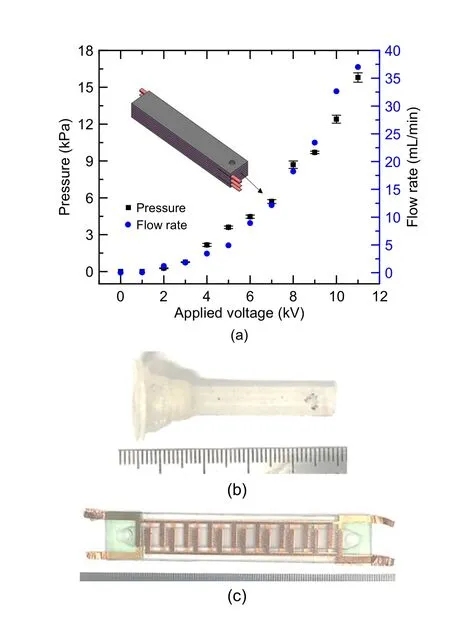
Fig.6 Characteristics of stacked pumps in terms of pressure and flow rate(a),eccentric tube made of Ecoflex-30 and adaptor made by a 3D printer(b),and stacked pumps(c)
3.3 EHD pump-based actuator
In this study,the stacked EHD pumps were integrated with the eccentric actuator (Video S1 in the electronic supplementary materials).We found that the eccentric actuator showed no apparent deflection when the applied voltage was less than 4 kV(Fig.7a).The eccentric actuator begins to bend with the increase of applied voltages.The bending angle(θ
)was defined by the tilt angle caused by the line,which was constructed by the top point and the tangential vector located at the right side of the actuator’s profile.In our case,the bending angle is limited (applied voltage:8 kV) because the tip of the actuator makes contact with the pumps (Fig.7c).The maximum bending angle is 221°as shown in Fig.7.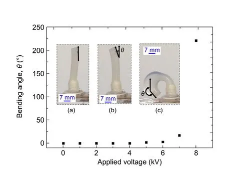
Fig.7 Relationship between the bending angle of the eccentric actuator and applied voltage on the EHD pumps:(a)1-4 kV;(b)7 kV;(c)8 kV
We also researched the response and release time of the eccentric actuator with applied voltages of 9 kV and 10 kV(Fig.8).The response time was calculated when the actuator bent to an angle of 240°.Taking the applied voltage of 10 kV for example,the actuator realized the bending and returning process at a period of 11 s (Figs.8a-8g).When the time is less than 8 s(response time),the bending angle increases with the increasing voltages.After shutting down the power supply,the bending actuator returned to the original position in 3 s.We found the response time was longer in the case of 9 kV than that in the case of 10 kV.This can be explained by the lower voltage giving a lower output power and causing a slower movement of the bending actuator.Nevertheless,the release time remains the same because it depends primarily on the elastomer modulus of the tube actuator.
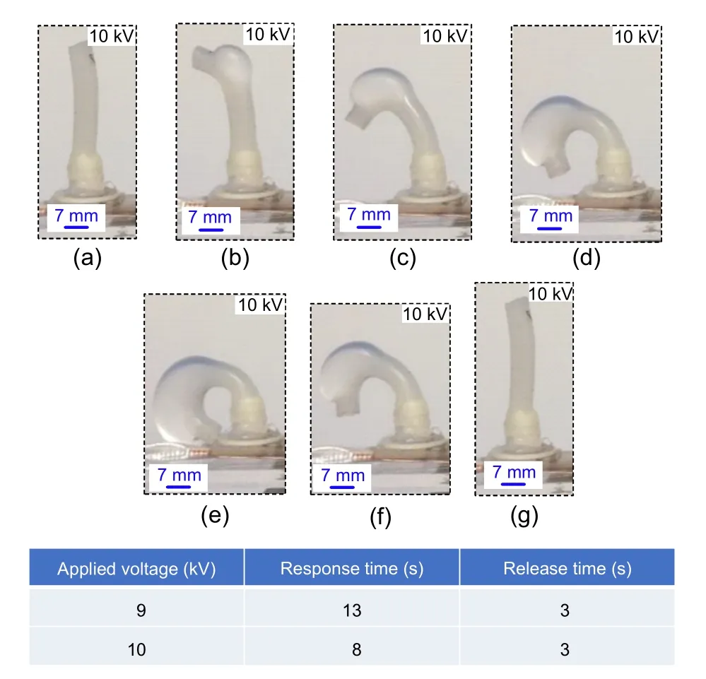
Fig.8 Response time and release time of the eccentric actuator(9 and 10 kV).Figs.8a-8g show the bending and releasing process of the actuator(10 kV)
5 Conclusions
In this study,we designed,fabricated,and characterized single-layer and stacked EHD pumps and applied them to drive an eccentric actuator.The proposed single EHD pumps were composed of transparent base and covers,and conductive copper electrodes.To boost the output power,we also developed stacked EHD pumps,made of four layers of EHD pumps.We used the Novec HFE 7300 as the pumping medium.The pumps and eccentric actuators were realized by using the two methods of digital fabrication and replication mold,respectively.The total dimensions of the stacked pumps were 113 mm×20 mm×3 mm.The performances of the single and stacked pumps were compared.The output pressure and flow rate of the stacked pumps were 15.8 kPa and 37.02 mL/min,respectively.In contrast,those values for the single pumps were 3.2 kPa and 24.09 mL/min,respectively.Finally,we employed stacked EHD pumps as eccentric actuators,and realized a bending angle of 240° in a short time of 8 s and a rapid return to the original position in 3 s.
Author contributions
Ze-bing MAO and Yota ASAI designed the research.Ze-bing MAO and Ardi WIRANATA processed the corresponding data and wrote the first draft of the manuscript.De-qing KONG and Jia MAN helped to organize the manuscript.Ze-bing MAO,Yota ASAI,and Ardi WIRANATA revised and edited the final version.
Conflict of interest
Ze-bing MAO,Yota ASAI,Ardi WIRANATA,De-qing KONG,and Jia MAN declare that they have no conflict of interest.
杂志排行
Journal of Zhejiang University-Science A(Applied Physics & Engineering)的其它文章
- Seal contact performance analysis of soft seals on high-pressure hydrogen charge valves
- Hydraulic directional valve fault diagnosis using a weighted adaptive fusion of multi-dimensional features of a multi-sensor
- Dynamic performance and control accuracy of a novel proportional valve with a switching technology-controlled pilot stage
- Mechanism analysis and evaluation of thermal effects on the operating point drift of servo valves
- Data-driven fault diagnosis of control valve with missing data based on modeling and deep residual shrinkage network
