Propagation of terahertz waves in nonuniform plasma slab under“electromagnetic window”
2022-03-12HaoLi李郝ZhengPingZhang张正平andXinYang杨鑫
Hao Li(李郝) Zheng-Ping Zhang(张正平) and Xin Yang(杨鑫)
1College of Big Data and Information Engineering,Guizhou University,Guiyang 550025,China
2Semiconductor Power Device Reliability Engineering Research Center of Ministry of Education,Guizhou University,Guiyang 550025,China
3Key Laboratory of Micro-Nano-Electronics and Software Technology of Guizhou Province,Guiyang 550025,China
Keywords: terahertz wave,scattering matrix method(SMM),nonuniform magnetized plasma,electric field
1. Introduction
At velocities near or above Mach 10, atmospheric gas flowing by the hypersonic vehicle will be heated by the supersonic shock in front of the vehicle. It creates friction violently when the atmospheric gas flows around the aircraft, causing the dissociation of molecules and atoms to form an ionized flow,or so-called“plasma sheath”.[1,2]The electron density of the plasma sheath can reach more than 1019m-3,[3]so that the electromagnetic wave energy emitted or received by the antenna window is absorbed in large amounts, making communication impossible. That is,the blackout phenomenon occurs. Many technologies have been proposed to alleviate the blackout problem,[4-9]such as aerodynamic shape, material injection,magnetic and electric field restraint,high-frequency transmission. With the development of electromagnetic materials and terahertz wave technology, additional electromagnetic fields and terahertz wave transmission have great potential in alleviating the blackout problem. The frequency of the THz wave is higher than the cut-off frequency of the highdensity plasma sheath currently studied. Hence, it has excellent penetration into the sheath. The THz wave also has good anti-interference, so researchers have begun to pay attention to the transmission of terahertz waves in plasma and the influence of magnetic fields on transmission. Zhouet al.studied the influence of non-uniform magnetic fields on the transmission of electromagnetic waves below Ka in the sheath.[10]Zhanget al.studied the transmission characteristics of terahertz waves in parallel magnetized sheaths,[11]Lemmeret al.investigated the effects of cross electric and magnetic fields on plasma sheaths.[12]Kimet al. studied the sheath electron density changes near the electrode under an electric field.[13]Therefore, the transmission characteristics of terahertz waves in the plasma sheath under the action of electric and magnetic fields are worth studying. Computer numerical analysis is more comfortable and efficient than the flight test with the high cost and harsh detection conditions. It is widely used to analyze electromagnetic wave transmission characteristics in plasma, such as through using the Wentzel-Kramer-Brillouin (WKB) method, scattering matrix method (SMM),finite-difference time-domain(FDTD)method.[14-25]Yuet al.used the WKB method to study the transmission characteristics of terahertz waves in magnetized plasmas with different electron density distributions.[26]Numerical simulation results demonstrated that the plasma density,plasma slab thickness, plasma density models, and collision frequency significantly influence the attenuation and transmittance of terahertz waves. Guoet al. used the SMM to study the transmission characteristics of terahertz waves in three parabolic magnetized plasmas.[27]Numerical calculation results show that the characteristics of the absorption spectra are affected by the parameters in the first layer of plasma and the gradient of the parameters across the entire plasma. Zhanget al. used the FDTD to study the three types of plasma absorptions, including plasma resonance, electron cyclotron resonance, and upper hybrid resonance in homogeneous and inhomogeneous magnetized plasmas.[28]The studies mentioned above focused mainly on the transmission characteristics of electromagnetic waves in non-uniform magnetized plasma magnetized in a fixed direction and have obtained many meaningful conclusions. However,they considered neither the influence of magnetic field inhomogeneity nor the effect of the electric field on the plasma sheath. These external conditions will also affect the transmission of terahertz waves in the sheath to a certain extent.
In previous work,using the SMM,we compared and analyzed the transmission characteristics of the left and righthand polarized THz waves when the various parameters changed.[29]However, we did not consider the non-uniform distribution of the magnetic field and did not add an electric field to the model to change the electron density distribution.Therefore, to explore the transmission characteristics of terahertz waves in the sheath more comprehensively, this paper considers the magnitude and direction of the inhomogeneous magnetic field,the influence of electric field on plasma density distribution and the collision frequency. Besides, the transmission performance before and after adding a magnetic field or electric field are compared. The SMM is also used in this work for calculation and analysis. Because the SMM makes fair use of the layering idea to reflect the inhomogeneity of plasma,by expressing the total electric and magnetic fields in each thin plasma layer,multiple reflections between layers can be considered. In addition, compared with the precise algorithm FDTD,it does not require a lot of meshes,and the transmittance can be calculated directly and efficiently. The SMM algorithm has low complexity and high computational efficiency, so it is very suitable for analyzing the plasma sheath.The rest of this article is arranged as follows. First, the total transmission model and the SMM model, and theoretical derivation are introduced. Then, before and after the electric or magnetic field is added, the transmission performance of the right-hand polarized terahertz wave in the plasma sheath is calculated and analyzed under different electron densities,magnetic field distributions, and different collision frequencies. Finally, some conclusions are drawn from the present studies.
2. Theory of SMM
We use the SMM to study the transmission characteristics of electromagnetic waves incident perpendicularly to the plasma sheath. The overall model used is shown in the crosssection of Fig.1.
Electromagnetic waves enter into the plasma in a vertical direction. The magnet under the antenna provides a nonuniform magnetic field to magnetize the plasma sheath on the aircraft’s surface. We simulate the magnetic field distribution of the magnet with the ANSYS Electronic Desktop V 19 and show the results from the model in Fig. 1. The simulation data will also be used in Section 3. In addition,in this model,we add positive electrode and negative electrode on the aircraft’s surface to introduce an electric field. An electrostatic plasma sheath is formed when a negative voltage is applied to the negative electrode in a plasma. In the electrostatic plasma sheath, the electrons are depleted due to the applied negative voltage.[13]And electrodes and antenna can move synchronously according to the position we require. Because it is assumed that it is non-uniform only in thex-axis direction,we will analyze the transmission of THz waves in the plasma layer in thexoyplane. Since magnetized plasma is a dispersive medium and possesses anisotropy,it can be divided into a certain number of thin layers with the same characteristics for analysis.

Fig.1. Lumped model of terahertz wave incident on plasma under applied electromagnetic field.
As shown in the layered model in Fig.2,the entire plasma sheath is divided intonlayers. The upper area (0) and lower area (t) are free spaces. Each layer of the layered plasma is regarded as a uniform plasma,and the propagation constant isk(m),
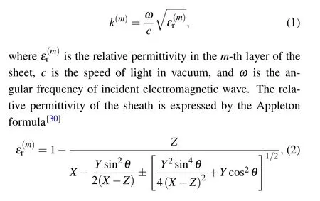
where sign±represents the left polarization or right polarization;θis the angle between the wave propagation path and the magnetization direction;X=1-iv/ω,withvbeing the collision angular frequency, andωrepresenting the incident electromagnetic wave angular frequency;Y=ω2ce/ω2, withωcebeing the electron cyclotron angular frequency;Z=ω2p,m/ω2,withωp,mbeing the plasma angular frequency of them-th layer.

Fig.2. Model of THz wave propagation in layered plasma.
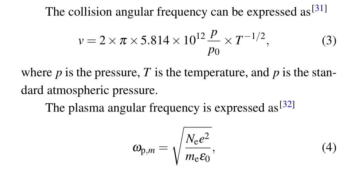
whereNeis the free electron density,eandmeare the electron charge and electron mass,respectively;ε0is the dielectric constant in a vacuum.
The electromagnetic field in the incident area 0 and the thin layer 1 in Fig. 1 are represented by the incident electric fieldEiz, the reflected electric fieldErz, the incident magnetic fieldHiy,and the reflected magnetic fieldHry. They are respectively written in the following forms:
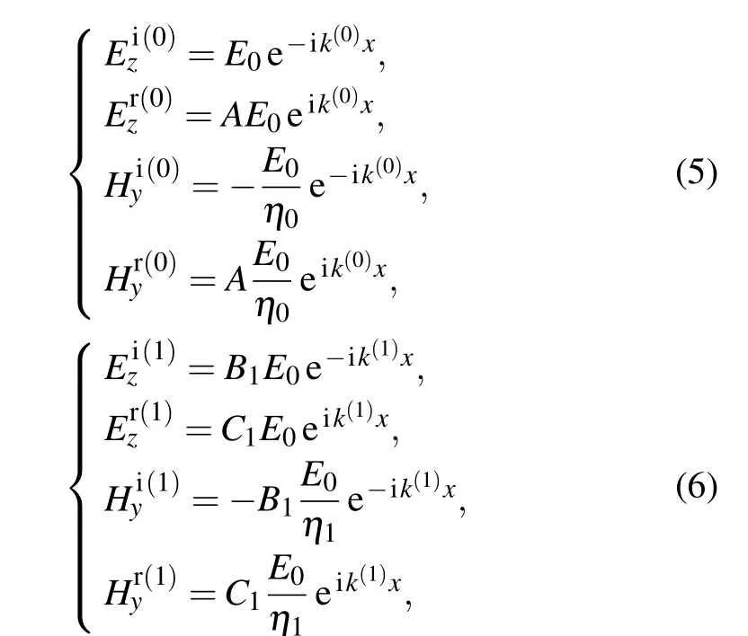
whereAis the reflection coefficient incident on the surface of the first plasma layer;B1is the transmission coefficient of the electromagnetic wave from the area 0 into the plasma layer 1;C1is the reflection coefficient of the electromagnetic wave from plasma layer 2 back to plasma layer;k(0)is the wave number in free space. In this way, the total electromagnetic field relationship between the incident area 0 and the thin layer 1 can be determined, and the matrix relation can be obtained by the imposed boundary conditions of the interface atx=0:
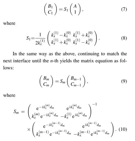
The left and right of the last interface are the plasma layer(n)and free space(t). There are only transmitted electromagnetic waves in the area (t) but no reflected electromagnetic waves. Therefore,matching the boundary conditions atx=dcan obtain a matrix equation

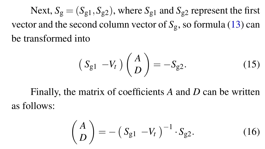
Then the normalized transmission power of electromagnetic wave is expressed as|D|2.
3. Numerical results and discussion
This part will discuss the transmission characteristics of the right-hand polarized terahertz wave in the plasma sheath under different parameters after having added a magnetic field and an electric field. According to the plasma parameter electrostatic probe measurement data of NASA’s reentry flight test,[1]the double Gaussian distribution can approximate the electron density distribution of the aircraft surface sheath and the specific distribution model expression is given below:

Note thatN0in this model indicates the maximum of the plasma electron density, anddis the thickness of the plasma layer. The coefficient is set to bea=300,b=220,d=0.1,andx0=0.06, respectively, to determine the position of the maximum electron density in the incident path. The specific distribution is shown in Fig.3(a).
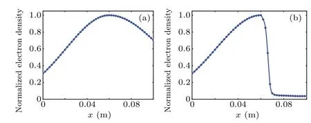
Fig.3. Electron density distribution of(a)before and(b)after adding electric field.
Research shows that an electrostatic plasma sheath is formed when a negative voltage is applied to a negative electrode in a plasma. In the electrostatic plasma sheath,the electrons are depleted due to the applied negative voltage,forming a low electron density area.[3,6,13]These researches show that when a-1000 V potential drop is applied across the two electrodes in plasma with an electron density of 1×10¹⁸m-3, a low electron density area will be generated around the negative electrode with a radius of about 3 cm to 4 cm. Thus in our work, we assume that the voltage applied to the positive electrode and negative electrode are 0 V and-1000 V,respectively, and assume that the radius of the low electron density region formed by the electric field is about 3 cm. Here we do not consider the distribution of electric fields for the time being. Figure 3(b)shows the radial electron density distribution when an electric field is added.
To verify the accuracy of the SMM in our work,we find other two research results and compare them. From Ref.[33],we can obtain an experimental result. From Ref.[18],we can obtain a simulated result based on the FDTD method under the same parameters. The absorption coefficient obtained separately by the SMM method, by the FDTD method and in experiment are demonstrated in Fig. 4. Here,d= 0.15 m,N0=7.9×10¹⁸m-3, andv=1.6×10¹¹s-1. We can observe that the simulated results by SMM are in good agreement with the results by accurate algorithm FDTD, and the locations of the absorption peaks in the two simulated results are very close to the experimental data. The difference between the simulation and the experimental data is considered to be caused by external conditions and by the parameter settings of the plasma.
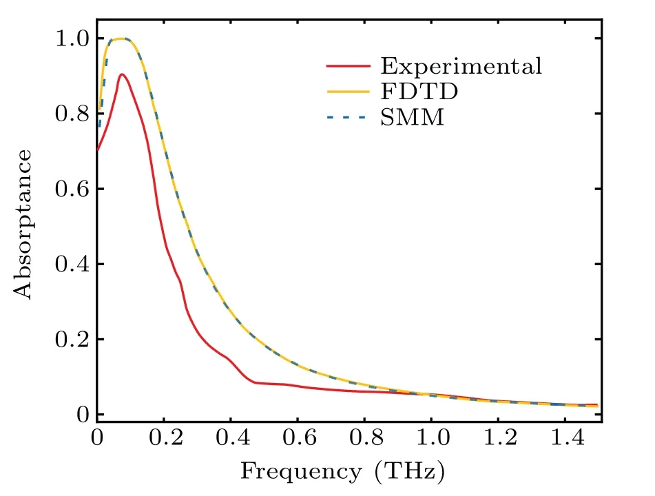
Fig.4. Plots of absorption coefficient of two simulation results and experimental results.
On this basis, the SMM can be used to calculate the influence of the external magnetic field and the external electric field on the transmission characteristics of terahertz wave in the plasma sheath. The peak electron density is an essential factor affecting the transmission of terahertz wave. Figure 5 shows the variations of normalized transmission power with frequency when the maximum electron densityN0is 1×10¹⁷m-3,1×10¹⁸m-3,and 1×10¹⁹m-3. At this time,the total thickness of plasma plate isd=10 cm, the number of layers isn=50, the collision frequency isfv=50 GHz,and the magnetic field strength isB=0 T orB=3 T. As the maximum electron density increases, the transmission power decreases, gradually forming a completely non-transmissible stop band at the low-frequency end. Figure 5(a) shows the comparison among the effects of adding a magnetic field to the transmission power for three different maximum electron densities. When electromagnetic waves propagate in a plasma with an external magnetic field, the electrons in the plasma will be subjected to a magnetic field to make a cyclotron motion.The right-hand polarized wave will rotate synchronously with the cyclotron electrons to form a cyclotron resonance, resulting in energy absorption. We can see that whenN0=1×10¹⁷m-3,B=3 T,and the magnetic field perpendicular to the incident direction of the terahertz wave,due to cyclotron resonance, the transmission power will first decrease and then increase with the increase of the wave frequency, forming a protruding peak, and the frequency corresponding to the top of the peak is near the cyclotron frequency.Comparing with the situation of no magnetic field,the transmission power increases at the low-frequency end,which is more conducive to the passage of electromagnetic waves.However,without a magnetic field,the THz wave shows better transmission in the high-frequency band. When the electron density increases to a certain value, a transmission stopband appears, and a magnetic field will make the stopband wider,but not conducive to electromagnetic wave transmission. Figure 5(b) shows the comparison among the electric field’s influences on the transmission power when there is no magnetic field. It can be seen that the transmission power increases to a certain extent after the electric field is added,and it is more evident at high electron density. In addition, we also investigate the case of adding the magnetic field and electric field at the same time. The influence on the transmission under the combined action of the magnetic field and the electric field is just the superposition of Fig.5(a)and Fig.5(b),so we will not analyze it here.
According to the model in Fig. 1, since the magnitude and direction distribution of the magnetic induction intensity provided by the permanent magnet is not uniform, the angleθbetween the incident electromagnetic wave and the magnetic field intensity vector will change due to different wave propagation positions. Figure 6 shows the magnetic field intensity distributions and direction distributions along the three paths above the permanent magnet simulated by the ANSYS Electronic Desktop V 19. Here we assume that the permanent magnet can achieve a sufficient large magnetic field intensity.
Figure 7 shows the variations of transmission power of terahertz wave with frequency when the wave is normally incident on the sheath along the three paths in Fig. 1. We can see that the magnetic field magnitude distribution along path 1 is not much different from along path 2. Still, the transmission performance along path 1 is better than along path 2. We can infer that the distribution of the magnetic field direction affects the transmission performance. Therefore,we will analyze the magnitude and direction of the magnetic field below separately.
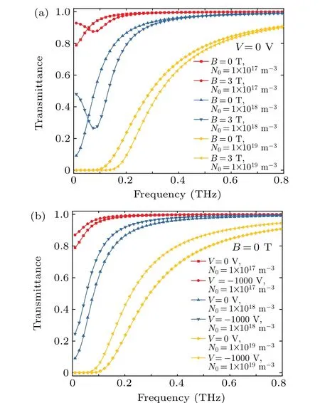
Fig.5. Influences of separately applied magnetic field and electric field on transmission under different electron densities(a)without electric field and(b)without magnetic field.

Fig.6. Distributions of(a)magnitudes and(b)directions of magnetic field along three paths.

Fig. 7. Variations of normalized transmission power with frequency along three paths.
As shown in Fig.8,the maximum electron density isN0=1×10¹⁸m-3,the collision frequency isfv=50 GHz,and the potential applied to the negative electrode isV=-1000 V.The magnetic field strengths in Fig. 8(a) are 1 T, 3 T, 5 T,respectively,and the magnetization angle is 90°. In the meantime,figure 8(b)shows the transmission coefficients when the magnetic field intensity is set to be 3 T, and the magnetization angles are 30°, 60°, and 90°, respectively. Figure 8(a)shows that with the magnetic field strength increasing,the absorption peaks move toward higher frequencies due to the cyclotron resonance effect. However, the absorption bandwidth is almost unchanged, so the transmission power at the lowfrequency end is much improved,and the transmission performance at the high-frequency end is weakened. On the other hand,as shown in Fig.8(b),as the angle between the direction of the magnetic field and the propagation path increases, the transmission power increases to a certain extent. In this way,by controlling the strength and direction of magnetic field,electromagnetic wave at a specific frequency can better pass through the plasma sheath.
Figure 9 shows the variations of the normalized transmission power with frequency of terahertz waves in the plasma sheath under different collision frequencies. Figures 9(a)-9(c)correspond to different situations: none of magnetic field and electric field, only magnetic field, both magnetic and electric fields. At this time, the values of the collision frequencyfvare 10 GHz, 50 GHz, 100 GHz, and 200 GHz, respectively,the maximum electron density isN0=1×10¹⁸m-3, the potential isV=0 V orV=-1000 V, and the magnetic field strength is 0 T or 3 T. We can see that the increase of collision frequency can also increase the transmission power at the low-frequency end, and the high collision frequency can inhibit the energy absorption caused by cyclotron resonance to some extent when a magnetic field is added. This result is due to frequent collisions between electrons,ions,and neutral particles,which weakens the cyclotron motion of electrons in the magnetic field. In this case,the absorption peak decreases,which is more conducive to transmitting right-polarized terahertz waves in a particular frequency band. Besides,after the electric field is added,the transmission power trend in the frequency band is almost unchanged,but the value is improved to a certain extent,which is more conducive to the transmission.

Fig. 8. Variations of of transmission power with frequency of THz wave(a) at different strengths and (b) in different directions of magnetic field strengths.

Fig.9. Influences of the collision frequency on the THz wave transmission at(a)V =0 V and B=0 T,(b)V =0 V and B=3 T,(c)V =1000 V and B=3 T.
4. Conclusions
In this work, both a magnetic field and an electric field are used to improve the transmission performance of terahertz wave in the sheath,considering the inhomogeneity of the magnetic field strength and direction distribution to the antenna window. The SMM is adopted to calculate and analyze the influences of maximum electron density,magnetic field magnitude,magnetic field direction,and collision frequency on the transmission power of right-hand polarized terahertz waves after adding a magnetic field or electric field. The calculation results show that the maximum electron density significantly affects the transmission of terahertz wave. The higher the electron density,the less the electromagnetic wave energy remains after passing through the sheath. After adding a magnetic field to the antenna window, the electromagnetic wave transmission power at the low-frequency end can increase to a certain extent,but it is not conducive to electromagnetic wave transmission with a frequency is near the cyclotron frequency.Both the strength and direction of magnetic field can improve the transmission performance of electromagnetic waves in the sheath to a certain extent. The magnetic field’s distribution perpendicular to the transmission direction is most conducive to transmitting right-hand polarized terahertz waves. Increasing the collision frequency can alleviate the energy absorption caused by cyclotron resonance to a certain extent. By appropriately adjusting the above parameters,the ability of electromagnetic waves to transmit in the plasma sheath at a particular frequency can be improved to a certain extent,and the blackout problem can be improved.
Acknowledgements
Project supported by the Open Foundation of Semiconductor Power Device Reliability Engineering Research Center of Ministry of Education, China (Grant No. ERCMEKFJJ2019-(05)), the Natural Science Foundation of Guizhou University, China(Grant No.(2019)62), and the China Scholarship Council(Grant No.202106675002).
杂志排行
Chinese Physics B的其它文章
- Measurements of the 107Ag neutron capture cross sections with pulse height weighting technique at the CSNS Back-n facility
- Measuring Loschmidt echo via Floquet engineering in superconducting circuits
- Electronic structure and spin-orbit coupling in ternary transition metal chalcogenides Cu2TlX2(X =Se,Te)
- Characterization of the N-polar GaN film grown on C-plane sapphire and misoriented C-plane sapphire substrates by MOCVD
- Review on typical applications and computational optimizations based on semiclassical methods in strong-field physics
- Quantum partial least squares regression algorithm for multiple correlation problem
