Railway ground vibration and mitigation measures:benchmarking of best practices
2022-03-11SlimaneOuakkaOlivierVerlindenGeorgesKouroussis
Slimane Ouakka•Olivier Verlinden•Georges Kouroussis
Abstract Vibration and noise aspects play a relevant role in the lifetime and comfort of urban areas and their residents.Among the different sources,the one coming from the rail transit system will play a central concern in the following years due to its sustainability.Ground-borne vibration and noise assessment as well as techniques to mitigate them become key elements of the environmental impact and the global enlargement planned for the railway industry.This paper aims to describe and compare the different mitigation systems existing and reported in literature through a comprehensive state of the art analysis providing the performance of each measure.First,an introduction to the ground-borne vibration and noise generated from the wheel-rail contact and its propagation through the transmission path is presented.Then,the impact and the different ways of evaluating and assessing these effects are presented,and the insertion loss indicator is introduced.Next,the different mitigation measures at different levels(vehicle,track,transmission path and receiver)are discussed by describing their possible application and their eff iciency in terms of insertion loss.Finally,a summary with inputs of how it is possible to address the future of mitigation systems is reported.
Keywords Ground-borne noise and vibration·Railway dynamics·Urban railway·Vibration mitigation·Insertion loss·Vibration isolation
1 Introduction
In modern times,ground-borne vibration and noise exposure to the residentsarehigher than theancient time,hence also their perception by people and all living beings.The ground-borne effects can be a serious concern for nearby neighbours of a transit system route such as rail and road traff ic,or maintenance facility such as blasting,pile-driving and operating heavy earth-moving types of equipment[1,2].
Among the possible sources,the one coming from the rail traff ic is of signif icant importance,due to the roleplaying in the transportation of contemporary society.In addition,according to the European vision,this is also expected to increasein thecoming yearsto beableto cover 50%of thetotal and transportation[3]sinceit isamong the most sustainable means of transport that can be a feasible alternative to the oil-based transportation[4].The expansion and development of railway lines inevitably lead the surrounding areas to be affected by the effects of the train passage,in the form of induced ground-borne vibration,ground-borne noise and air-borne noise[5]as depicted in Fig.1.Thesenegativeeffectshavebeen to acertain extent a limitation for the development of railways,especially in urban areas where signif icant levels of vibration to which residents in proximity to the lines are subjected[6].
Ground-borne vibration(which is the most commonly perceived sort of‘‘vibration’’)is generated by the interaction between trains,track and subsoil.The vibration is then transmitted through the ground and may reach the foundation of abuilding.The building respondsto the vibration of the foundations,and then the vibration is transmitted through the building structure and may be observed with the oscillation of f loors and walls.Ground-borne vibration is associated with a frequency range of roughly between 1 and 100 Hz[7].Correspondingly,it is def ined by the ISO 14837-1[8],as the‘‘vibration generated from the pass-by of the vehicle on the rail,propagated through the ground or structure into a receiving building’’.
On the other hand,ground-borne railway noise is def ined in ISO 14837-1[8],as‘‘noise generated inside a building by ground-borne vibration generated from the pass-by of a vehicle on rail’’.It includes both heavy and light rail transit as well as low and high-speed trains(HSTs).Notice that ground-borne noise is sometimes referred to as re-radiated noise,structure-borne noise[9]or solid-borne noise(according to ISO 14837);in this manuscript,it will refereed as ground-borne noise.Its frequency range is roughly between 20 and 250 Hz[7].
Air-borne railway noise is instead generated by the wheel-rail contact and the different train on-board equipment(e.g.,traction,ventilation and air conditioning)[10,11];the noise is radiated by the track and the surface train,then travels through the air toward the nearby buildings,where it istransmitted through the facadesinside buildings as audible noise.In the propagation paths(air in this case),numerous phenomena are attenuating the noise,for instance,the distance between the source and the resident[12,13]and the sound insulation of the facade[14].Air-borne noise can be in the full audio range between 20 and 20,000 Hz.However,air-borne is beyond the intent of this research,which focuses on the other two effects that propagate through the ground i.e.,ground-borne noise and vibration,presented above.
Both vibration and noise have been a subject of serious concern in public opinion due to the caused annoyance that inf luences the daily life of the exposed people(e.g.,sleep,communication,etc.)[15,16].Furthermore,the prospected amplif ication in the European and global railway grid,to meet the needs in the transportation of people and goods within the low carbon targets,will certainly convey to an increase in the number of trains which in turn will inevitably lead to an enhancement in the annoyance[17,18].
Recent studies and investigations have highlighted in addition to the annoyance,some permanent effects on the health of the exposed people.For example,the investigation made in 2013 by Croy et al.[19]have demonstrated that in some circumstance the passage of trains provokes acceleration of the heart rate during sleep up to 3 bpm,and this in long term may affect cardiovascular functioning of persons living close to railways.Whereas,the interview study done by Maclachlan et al.in 2017[20]have demonstrated that vibrations from rail transport for those living in proximity to the source,have negative repercussions for restoration all-day-long and that this exposure may have long-term health effects,as a result of disruption to the body’s normal homeostatic stress response.
For better understanding of the ground-borne effects,different researches and investigations have been conducted in the last four decades.The International Union of Railways(UIC)gave recently a general overview of the state of the art in induced vibration[7].Other research had a focus on the different parts involved in the railway environment like Kouroussis et al.[21,22]and Ouakka et al.[23].Whereas,further studies such as Smith et al.[24,25],Öhrstro¨m[26]and Kouroussiset al.[27,28]have put the emphasis on the consequences of the effects to nearby structure and the residents.
Due to the nature of the problem and its complexity,it is not straightforward to predict the propagation and the intensity of the ground-borne effects.The assessment of these effects will be discussed in detail later in this paper.However,it is obvious that the more accurate approach is to investigate the effects by direct measurements in the f ield[29,30]or by reproducing the railway environment with laboratory tests(e.g.,[31]).On the other hand,these two approaches have some drawbacks including time and budget cost,and in the case of f ield measurements,these are only applicable to existing grids(or to a physical prototype).The economic and valuable alternative to laboratory tests is the use of numerical simulations(aka virtual prototyping),as this has been demonstrated in railway[32–36],as well as in other different f ields[37,38].
With numerical simulations,it is possible to reproduce the railway environment and not only,but this can also be seen as a great point since the models needed to combine different elements from the source to the receiver and beyond these.A number of numerical models,based on f initeelement and boundary element approaches,have been developed by various research teams in an attempt to understand the propagation of railway induced vibration.Both in frequency domain[39–42]and time-domain[43–45]approaches have been considered.For example,the model developed by Kouroussis et al.[46,47]represents a promising way to consider the whole vehicle/track/soil/receiver system by working in two steps in order to separate each subsystem and to easily evaluate the contribution of each subdomain.
Finally,the purpose of this document is dictated by the importance of having knowledge and strategieson how to reduce ground vibration effects coming from the rail passage,in order to be able to implement and develop them.Mitigation systems,of which this research gives a review,areof different natureand can beapplied in all the interesting subsystems(i.e.,vehicle,track and propagation path)and the affected entity(i.e.,neighbouring buildings,equipment and people).Some preceding studies in how to mitigate the effects of the railway passage have been conducted in the last years[27,48,49].However,due to the variety and complexity of the problem,there are many other ways for improvements.Therefore,this paper gives an overall overview considering also the recent advancement in the f ield,as discussed in the following sections.
2 Ground-borne vibration and noise
In this section,the characteristics and the effects of vibrations coming from wheel-rail contact will be presented.However,since the acceptable noise and vibration thresholds change from country to country,different standards and guidelines are available in the literature to def ine adequate procedures and assessments in the area where the rail line is operating.This is also because countries generally do not have a comprehensive regulation to mitigate the vibration coming from the railway,but they generally provide only guidelines and recommendations based on a range of standards,either international or regional:
– ISO 2631[50,51],which are often considered as a reference for comfort evaluation,
– EN 12299[52],that def ines and evaluates the train passenger comfort,
– ISO 4866[53],for measurement and processing data with regard to evaluating vibration effects on structures;
or national standards:
– the British Standards BS 6841[54]and BS 6472-1[55]considered very similar to the aforementioned ISO standards,
– the German standards DIN 4150[56,57],used also in UK,Belgium and other European countries,
– the Swiss standards SN 640 312a[58]dealing with building damage only,
– the Norwegian standard NS 8176[59]for comfort assessment,
– the recommendations[60,61]of the United States Department of transportation(USDOT)for assessment of vibration impacts from high-speed train lines.
2.1 Generation of the vibration
Ground-borne vibration and noise are generated at the wheel/rail interface as indicated in Fig.2[62].When the vehicle travels on the rail,the quasi-static and the dynamic forces arise from the contact points[63].
Quasi-static forces are the outcome of the self-weight of thetrain,and they dominatenear thef ield up to one-quarter of the wavelength[5].The quasi-static def lection of a typical track is a picture of such forces(and thus of the vibration generated).This is illustrated in Fig.3 and can be deduced from a simple conf iguration(the track as an Euler beam on an elastic foundation),as in[64,65]:
where w(x,t)is the track def lection at position x and time t,Eris the rail Young’s modulus,Iris the second moment of area of the Euler beam,P is the train load,mwis the wheelset mass,and v0is the constant speed,whereas kfis the stiffness for unit length of the Winkler foundation,βis a constant def ined as
and representstheratio between thefoundation and the rail f lexibilities.
On the other hand,the dynamic excitation is speed-dependent and is the outcome of componentssuch aschanges in stiffness due to sleeper displacement,irregularities at the wheel/rail interface(these are becoming lessinf luential due to the improvement in the design and maintenance of the components)and soil support conditions.At the same time,the characteristic of the vibration waves produced by the rail traff ic have specif ic properties depending on the type of line and/or vehicle.These are typically subdivided into the following four cases[64]:
– Underground trains—Generate vibrations with a higher frequency spectrum than over-ground tracks.
– High-speed trains—Generateelevated amplitudevibrations due to their increased speeds if the speed reaches one of the waves in the soil the vibration levels may rise.
– Urban tramways—Generate low amplitude vibration,but they can cause structural damages to buildings in their proximity.
– Freight trains—Generate high amplitude,low-frequency vibration(for their low speed)that can propagate to large distances from the source.
2.2 Propagation of the vibrations
Once the vibrations are generated at the wheel-track contact,they propagate through the soil as compression waves(Pwaves),shearwaves(S-waves)and Rayleighwaves,see Fig.4.Primary or compression waves(P-waves)are longitudinal waves with the highest propagation velocity with the lowest energy transmitted.Whereas,shear waves(S-waves)propagate transversely,generally in an oblique direction into the soil[41,67,68].
The analytical formulas to calculate P-and S-wave speeds are given in Eqs.(3)and(4),respectively[64].
whereρis the density,κis the bulk modulus,and G is the shear modulus of the soil.
Last,Rayleigh waves are the most important for the excitation of buildings,these are also known as surface waves because they occur at the surface of the soil.In underground lines,Rayleigh waves are arising from the ground surface ref lection of P-and S-waves[69–71].To notice that Rayleigh waves can only occur in a homogeneous half-space medium or in more complicated but with a single apparent velocity as a function of the frequency.Further to the aforementioned waves in theory others are possible.
2.3 Impact and assessment of the vibrations on urban areas
The impact and assessment of the induced vibration may have different effects depending on the intensity of the signal in all three directions(standards take generally the highest or the average value as reference).At the same time,it is important also to take into account the type of train(freight or passenger trains,see Table 1).In addition,some vibrations are classif ied as feeble(negligible),those that are below the threshold of perception[72],not relevant for the scope of this study.Instead,the noticeable groundborne vibrations could have the two following negative effects:
– Annoyance to humans,
– Damage to buildings and equipment.
Damage to buildings caused by railway induced vibrations are of secondary importance,and in case of occurrence causes mostly cosmetic damages(and rarely structural ones),these type of effects are taken into account for example by British Standard BS 7385-2 Code[73].
On thecontrary,moreimportant isthedisturbancecaused by railway passage to humans.According to the ISO 2631-2:2003[51],the threshold of perception expressed in an RMSvalue(root mean square of the signal),which liesat a vibration strength of approximately 1 mm/s at 1 Hz and 0.1 mm/s at 10 Hz and higher(whereas the ground-borne vibration level caused by therail traff ic rangesbetween 10 to 80 Hz).At the same time,it is important to notice that differences between individuals may occur depending on their sensitivity.In the ISO 2631-1:1997[50],the absolute threshold of perception of weighted vertical vibration is stated to be around 0.015 m/s2.
In addition to the vibration,there is the noise coming from the motion that the vibration itself is causing,the socalled ground-borne noise,for which the acceptable level can be derived from legal limits for environmental noise,which are 35–40 dB(A) during the day and 25–30 dB(A)during night time.Recently,there are also studies that have state also some permanent effects in human health caused by these vibrations in addition to the only annoyance[19,74–76].
An additional aspect,that can unfortunately increase the induced ground vibration levels toward aforementioned nearby buildings and humans,is the enhancement of the passengers’pleasure in order to provide an environment conducive to work,i.e.,reading and writing skills are not diminished particularly on high-speed lines(see Table 2).Consequently,new designs and measures could twist between the two features.
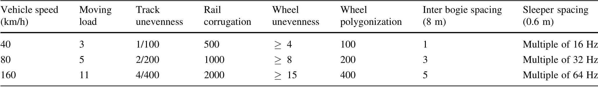
Table 1 Frequency of typical vibration for each of the generating mechanisms,depending on train speed[7](unit:Hz)

Table 2 Vehicle vibration effects on passengers
3 Concept of vibration isolation
3.1 On the use of transmissibilities
Sincethefollowing part(Sect.4)will describethedifferent mitigation measures,that are governed by principles on vibration isolation.In this section,the idea of vibration isolation will be presented by consideration of a singledegree-of-freedom system(Fig.5).It can be seen as a rigidbody connected to a foundation by an isolator that has resilience(spring)and dissipation(damper)of the energy.Theperformance of theisolator may beevaluated by the following characteristic values[80]:
– Absolute transmissibility(TA),which is a measure of the reduction of transmitted force or motion afforded by an isolator,
– Relative transmissibility,which is the ratio of the relative def lection amplitude of the isolator to the displacement amplitude imposed at the foundation,
– Motion response,which is the ratio of the displacement amplitude of the equipment to the quotient obtained by dividing the excitation force amplitude by the static stiffness of the isolator.
These characteristics use steady-state displacement transmissibilities as a function of the frequency f or the circular frequencyω (ω=2πf),and in practice,the absolute transmissibility is retained(φis simply the phase of the signal).By considering a viscous damper,the transmissibility is given by Eq.(5):
where X is the amplitude of the mass response,Y the amplitude of the foundation motion,ξthe damping ratio,andΩthe frequency ratio(ω/ωnwhereωnis the circular natural frequency of the single-degree-of-freedom system).
In addition,it is important to have in mind that track mitigation measures are often characterized by a transmissibility curve(Fig.6)as a function of the frequency.Three zones can be distinguished:zone 1 when the transmissibility is close to 1(no effect of the mitigation measure);zone 2 when the transmissibility is greater than 1(negative effect of the mitigation measure)and zone 3 when the transmissibility is lower than 1(positive effect of the mitigation measure).Notice that for zone 3,the smaller thedamping ratio,thegreater thevibration attenuation.The choice of support stiffness is,however,limited by the allowable vertical static displacementsunder theaxle loads of the train,and some excitation frequency(covering zone 2)may be amplif ied.Such effects were generally observed for f loating-slab systems[81–83].
Generally,the isolation becomes effective when the frequency ratio exceed.If the ratio is less than,the vibration may easily be amplif ied[84]and the isolator does more harm than good.
Notice that,due to the nature of material damping,viscous damping is not well adapted(since its effect increases with the frequency of motion),and hysteretic damping ispreferred(no dependence with the frequency of harmonic motion),even it does present a real relationship in the time domain.
3.2 Insertion loss
In railway vibration,the effectiveness of the mitigation solutions described in Sect.4 that are generally expressed in dB as insertion loss(IL)[7],i.e.,the difference in vibration,between the original conf iguration and the application of the measure.In other words,the IL is obtained as shown in Eq.(6)from the ratio of the particle displacement of the conf iguration without and with mitigation measure[85,86]:
where urefis the velocity without mitigation measure(nominal conf iguration)and u the velocity after introducing the mitigation measure.
It isstraightforward from Eq.(7)that if thedisplacement is half after inserting the mitigation measure the IL will be 6 dB,while a negative value would only occur in case the measure has the opposite effect.The concept of vibration isolation presented in this section governs as a whole the mitigation measures,and therefore,the techniques introduced in the following section,and those will be evaluated according to the IL as anticipated.
4 Mitigation systems
In order to suppress and/or reduce the negative effects of ground-borne noise and vibration,different mitigation measures have been analysed and tested in the past years.These improvements can be applied to new infrastructure and/or existing ones,the different methodologies are to be compared both with their feasibility and thecoststo be able to use them most conveniently.For the purpose of this research and to give a complete understanding of the state of the art of these improvements.In this section,the major available technologies will be illustrated and discussed exhaustively.
The mitigation systems can be applied in all three parts of the railway system,on the vehicle,on the track and on the transmission path(that is generally soil).It is also possible to make improvements directly at the receivers(i.e.,buildings).Many of those have been tested in laboratories using full-scale and scaled models.But it comes out,due to the nature of the problem,that computer simulations after calibration using the experience from real projects are the right solution to proceed feasibly and competitively concerning physical models.
For simplicity,in this paper,the parts of the railway environment(where the mitigation measure are possible)are subdivided into four main subsystems:vehicle,track,transmission path,and receiver.Based on the different rail systems,the characteristics of the aforementioned components change from one to another.In literature are mainly subdivided in terms of new and retrof itting of existing lines,or in terms of surface and the underground lines.
4.1 Improvement in the vehicle
The vehicle dynamics play a crucial role in the generation of the ground-borne effects,principally when irregularities are present at the wheel-rail contact[87–89].
These days,rail vehicles are constructed using bogie system technology,with a single and double suspension,for the freight and passenger trains,respectively.Primary suspensions connecting the wheelsets to the bogie frame and are made with coil or rubber springs.Secondary suspension systems,located between the bogie and the car body,consist of elastomer elements,air spring or metal spring.Wilson et al.[90]demonstrated that aproper design of the bogie suspension can signif icantly reduce the levels of ground vibration.In general,vehicles with soft primary suspension produce lower levels of vibration than vehicles equipped with stiff suspensions[91–93].It is also important to highlight that the way in which the vehicle affects the generation of the vibrations dependson the typeof train and the technology that is used.
Despite the importance of the vehicle design parameters toward the generation of the ground-borne noise,the majority of efforts and research have been focusing on the other two sub-systems(track and ground)of the railway environment,which will bediscussed later in Sects.4.2 and 4.3.Thisisbecause the manufacturesof trainsfocuson the car design within the ride comfort,stability and gauge in order to enhance the passengers’pleasure(see Table 2).

Table 3 Vibration reduction at source—rail vehicles

Table 4 Vibration reduction at source—track

Table 5 Vibration reduction at the transmission path
Therefore,the different measures that can be applied to the means of transportation have to deal with the reduction of the effects of the rail passage but at the same time have to maintain the train passengers comfort at the highest standards.Theimportanceof improvement of thevehicleis crucial for the ground-borne vibration since this effect is arising between the track and wheel contact,with the latter being a component of the train.
The principal measures to control and/or mitigate the ground-borne vibration coming from the vehicles will be presented in the sub-section and are the following:
– Improving wheel roundness,
– Reduction of the unsprung mass,
– Reduction of speed,
– Resilient wheels.
When the main contributor in the vehicle is identif ied,it is possible to design the vehicle so as the dynamic forces acting on the track are reduced.It should be noted that wheel out of roundness and the unsprung mass of a single wheel are often the dominant excitation mechanisms[94].
4.1.1 Improving wheel roundness
Wheels out of roundness are one of the main causes of excessive vibration and are the result of the manufacturing process or repeated loading at high frequencies[95].The most common manifestation istheformation of wheel f lats,caused primarily by train breaking/deceleration,and this results in high-frequency impact force whenever the corners of the wheel f lat impact the rail during the rotation.Instead,Fig.7 shows an example of wheel polygonalization in the f irst-,second-and third-order.The orders here are just taken as a reference.However,these can increase up to 23rd as reported by Wu et al.[96]or even more.
This can be achieved with good maintenance of the wheels,improvement of the sliding protection and steel quality.In particular,re-prof iling,a high-quality wheel grinding program ensures the reduction of noise levels in the range of 5 to 10 dB.
4.1.2 Reduction of the unsprung mass
The unsprung mass is def ined as the set of the loads generated by suspensions,wheels and bogies frames.This mass laying directly on the rail beams is the main cause of the damage to the tracks.Therefore,its reduction becomes relevant in terms of track and infrastructure damage and consequently with respect to thereduction of thevibrations level.However,the decrease of this mass is diff icult to achieve due to safety criteria,wheels life and the vehicle dynamics design.
The wheel-set mass is generally in the range of 700–3500 kg,from small-diameter wheels on freight wagons to large diameter locomotive wheels.Its reduction can be obtained by the optimization of the cross-section in its shape and/or material and is generally limited to 5%–10%of the nominal wheel mass,with which is possible to achieve a vibration reduction of 2–4 dB in the long-term[94].In addition,the reduction of the radial thickness would reduce wheel mass signif icantly but at the same time inf luence the number of re-prof ilings,wheel life and production costs.
4.1.3 Reduction of speed
A central role in the generation of ground-borne noise and vibration plays vehicle speed.Therefore,as its value changes the amount of ground-borne vibration and noise is affected.In particular,by reducing the train speed by a factor of two it is possible to reduce vibration levels approximately up to 6 dB[61].
For example at the beginning of the 1990s in the project of the high-speed trains(HST)at Ledsgard(Sweden)[97],different interventions were made in order to mitigate the generated vibrations.Traff ic with HST started in spring 1997 with a speed of 200 km/h.Shortly afterwards,excessive vibrations were observed in some sites.These vibrations were in the order of ten times greater than those measured earlier from heavy train traff ic in soft soil conditions and had been regarded as the worst case.Train speed was reduced to 160 km/h and later to 130 km/h.Thanks to these reductions of the operational speed of the HST line from 190 to 130 km/h it was possible to achieve an IL of 26 dB at 12 metersfrom the source,asreported in Fig.8.
In general,when the train speed is approaching the Rayleigh wave speed of the transmission path it ispossible to have considerable growth in the track vibration and consequently an increase in the ground-borne effects[98,99]as in the case of the aforementioned Ledsgard project.Experimental demonstration of these effects has been redrawn for three sites located in Sweden,UK and Netherlands,by Connolly et al.[64,100]as depicted in Fig.9.It is straightforward that as the normalized speed(train velocity/Rayleigh wave speed)approaches unity,the track displacement increases exponentially.
In addition to the speed of the train,many other factors inf luence the vibration propagation,such as types of railway vehicles,transport type(passenger or freight),track typeand others[101].In particular,thishasbeen discussed by Thompson et al.[62]that presented a prediction of the wavef ield generated by a point load of constant unit amplitude for three load speeds:80,168 and 250 m/s as depicted in Fig.10.
Figure 10a shows the wave-f ield generated by the load moving at a speed that is below the wave phase velocities of the surface waves,here the wave speed is very low.Whereas,when the load speed is close to the Rayleigh wave speed of the upper layer,in Fig.10b,the wave-f ield generated changes and the displacement amplitudes are signif icantly larger.If the velocity increase up to 250 m/s,as in Fig.10c,the waves generated travel with signif icant amplitude away from the load.
Therefore,in order to get advantagesfrom the reduction of the speed would be necessary to f ind the less impacting speed during the motion,depending on the type of train,type of transmission path(that will be discussed in Sect.4.3),and other components.Even if vibration levelscan be reduced up to 6 dB,the numerous factors involved in the process do not make speed reduction among favourite choices when developing mitigation systems.On the other hand,a disadvantage of this approach is that it has a high cost in a long time because the line capacity is reduced.
4.1.4 Resilient wheels
Resilient wheels are more effective in eliminating wheel squeal on tight turns where reductions of 10–20 dB[61].However,it is also possible to have a reduction in vibration in the range of 3–6 dB.
Figure 11 shows the positive effect of changing the stiffness of resilient wheel equipping trams in order to reduce the transmitted ground vibrations,in terms of IL,noticethat thestandard wheel haveastiffnessof 145 MN/m decreased in the illustrated case to 13 and 18 MN/m.This also demonstrates the real interest of a compound vehicletrack-soil model in the design of this kind of wheel[102].
4.2 Improvement in the track
In urban areas where the railway effects are of more concern,it is quite logical and straightforward to understand that mitigation measures at the source(vehicle and wheeltrack)are more convenient than the ones applied both in the path(ground)and in the receiver(surrounding resident and constructions).This isfor the reason that by mitigating at sourcesall thesurrounding receiversareprotected,while with the protection at the receivers it is necessary to produceasystem for each receiver.On theother hand,in areas where we have less neighbourhood might be convenient to intervene in the receiver.
Keeping the conf lictsthat the design of thevehicle could have in terms of internal comfort,and the generation vibration the improvements in the track achieves a crucial role in the quest to mitigate negative effects coming from the rail traff ic.Additionally,as it can be seen in Fig.12,among thenumerousdynamic excitationsthat contributeto railway vibrations,the excitation due to the vehicle are found at low frequencies,and theexcitation associated with the wheel,rail and track is found at higher frequencies.
Before introducing the improvements that can be applied to the track,it is worth to brief ly present the track system and its component[103]:
– Rail is the main part of railway track,acts as two parallel lines.
– Rail pad is designed between the sleeper plate and foot of the rail,generally made by an elastic polyurethane mat.Together with spikes and the fasteners joining the steel rails to the sleepers.
– Sleepers is laid perpendicular to steel rail.Railway sleeper can be properly deformed to trimmer pressure when thetrain passesthrough and aregenerally of three types(wooden,steel and concrete sleeper).
– Ballast bed is a layer of free-draining coarse aggregate used as a bed elastic support for sleepers.
An important factor for the ground-borne effects is the overall track stiffness.Indeed if too low thereisan increase in the deformation of the soil and ballast,while on the contrary when the stiffness is too high a corrugation is easier to be generated[104].Additionally,if the stiffness has radical f luctuations over the track section then also in this case track deterioration and vibration are increased[105].The values of stiffness change from country to country based on types of traff ic that are expected(e.g.,freight or passenger transport),consequently it is diff icult to f ix an ideal value of the stiffness since generally,the lines host various types of trains.Therefore,track imperfection and degradation(not only due to track stiffness)are crucial to the track vibrations.
Therefore,a correct selection of these elements(rail,fastening,sleepers,ballast)plays a central role in diminishing the formation and propagation of vibration.Increasing the f lexibility of the superstructure components raises their ability to damp(dissipate)vibration generated at wheel-rail interface[106].
4.2.1 Rail enhancements
The irregularity in the track and the ballast can be an important source of vibration.Indeed,a good track alignment can provide a 10 dB reduction for the ground-borne noise for speeds at 320 km/h,therefore,maintenance to the rail plays an important role in the vibration mitigation.
Embedded rail systemsarealso an alternative(Fig.14d),typically used in urban tram lines.In these systems,the rail isembedded in aconcreteslab which isthen either f illed by pouring out elastic embedding material(at the bridgessteel moulds are applied)or by the installation of prefabricated rubber parts around the rail web,with a wedge on either side to keep therail in place.Eszter et al.[107]showed that the elimination of metal-to-metal contact contributes to a reduction up to 8 dB in the frequency range 5–200 Hz;Whereas,Lakusˇic´et al.[106]showed a vibration reduction between 12.9 and 18.6 dB in a tram line after implementation of continuously embedded rails depending on the tram vehicle type.
Rail dampers can also be used for vibration mitigation.These are prefabricated passive elements in steel material,which are f ixed to both sidesof the rail web serve to reduce the vibration of the rails.Rail dampers are usually installed between every sleeper in problematic areas of the track.Studies conducted by German(DB)and French(SNCF)Railways,at the rail track sections with rail dampers installed,showed an in vibration up to 9 dB[108].
4.2.2 Fasteners enhancements
Rail fasteners are used mostly,even if several improvements have been made over the years are the one presented a long time ago,named resilient rail fasteners.However,with therecent application of new designswhere the rail is supported by resilient blocks such as in the Thameslink project in London,it has been possible to have a reduction of 13 dB in ground-borne noise[109].
Additional studies have demonstrated that high resilience fastening systems(Fig.13a),in which elastic elements supporting the rail at the web prevent direct contact between the rail foot and sleeper,allows signif icantly greater vertical def lection of the rails under operation,gaining a low vertical stiffness of the entire system that reduces vibrations by 5–10 dB at frequencies above Hz[61].Instead of rail fasteners with a highly resilient under base-plate pad(Fig.13b),where the resilient pad is precompressed with aload equivalent to 80%thenormal static load on thefastener during vehicle passage[110],vibration isolation of 20 dB isensured with range frequency between 25 and 20 Hz[111],to notice that in this last case the spring is unloaded during the train passage and as a result,there is no vibration transmission to the lower parts of the track.
4.2.3 Sleepers and ballast enhancements
The sleeper can be installed in concrete or wood.Concrete sleepers are the most used type because of different economical advantages(simpler installation,greater durability,lower maintenance and operation costs),but wooden sleepers present a higher vibration damping capacity[113,114].The studies made by FTA[61]showed a vibration reduction by 5 dB when using wooden sleepers.At the same time,there are also other important improvementsthat can bedonejust under thetrack in order to achieve vibration attenuation,such as by placing the elastomeric pads between the sleepers and the ballast bed.This elastomeric pad is usually composed of two layers of different material,the upper made by viscoelastic rubber with high vibration damping ability and the lower layer isa coarse geotextile that serves to prevent possible upper layer damage from impressing of crushed ballast material[106].UIC stated in[7]that for pads under the sleepers a reduction of 8–20 dB can be archived.Thesepadshave the advantage that they are easy to install during a sleeper renewal operation since they are delivered already f ixed to the bottom of the sleeper[115].Whereas,for the ballast mats(that can be applied to both the surface and underground systems)the reduction ranges from 3 to 15 dB.However,if a ballast mat is too soft there is a risk that the ballast layer becomes more feeble when solicited to the vibration produced by the passing train.Therefore,this could compromise the ride quality unless rigorous maintenance is performed(increasing in costs)[116].
4.2.4 Alternative track technologies
In the track improvements,the technology of the track itself plays a crucial role and,in addition to the classical ballasted track,there are other approaches with different track design concepts projected in order to mitigate the ground-borne noise and vibration.
The most common measures to mitigate the groundborne effects in ballasted track presented above and some possible alternatives(which will be presented further down)aredepicted in theorder of cost upwardsfrom top to bottom,in Fig.14.
In reference to vibration damping,track structures with ballast bed are better than the track structures on special reinforced concrete slabs the commonly named slab tracks(where the ballast is replaced by a rigid concrete track slab which transfers the load and provides track stability),with up to 3–5 dB of enhancement[117].The main disadvantage of this type of track construction,compared with tracks laid in ballast bed,is its greater rigidity,which results in increased vibrations.Further reduction of the vibration propagation can be achieved by increasing the height of the ballast bed,the German Railways(DB)[117]showed that an increase in the ballast bed height from the usual 30 to 75 cm can reduce the vibrations by 6 dB at frequencies lower than 10 Hz.
Another alternative to ballasted tracks is the f loatingslab tracks.These are special types of slab tracks with the so-called mass-spring systems principle,here the track is mounted on a thick concretes lab that rests on rubber bearings,glassf ibreor steel springs.With such designs,the highest possible mass is added above the track spring to form a system with a very low resonance frequency.
Floating-slab tracks are typically used to manage the vibration and ground-borne noise from underground trains where a large reduction is required[118].As well as the greater construction cost of the track form itself,the great expense can come from any increase in the diameter of the tunnel that has to be made to accommodate suff icient mass for the f loating lab.The slab may be cast in-situ,resulting in a continuous piece of concrete,or maybe constructed in discrete precast sections laid end to end.Continuous slab designs usually have a lower def lection for a given resonance frequency and make maximum use of the tunnel space but have the disadvantage that they are harder to design in such a way that the slab mounts can be replaced[62].
Studies have shown that the natural frequency of such structures lies between 8 and 12 Hz,depending on the material used and the total weight of the structure.The application of f loating slaps and other mass-spring systems allows the vibration reduction by 10 dB with frequencies above 16 Hz or by 25 dB with frequencies of 125 Hz[16].Whereas vibration measurements performed on a f loating track with ballast bed and spacing of the springs in 3,7 m showed that the system has 90% vibration isolation eff iciency,and the transmission loss was about 40 dB between 10 and 100 Hz frequency[107].
Thismeasure of allocating the rail line in tunnelshas the greatest reduction of noise and vibration and can achieve up to 40 dB as aforementioned[107,119].However,this technology can present some limitations due to the high costs of construction,service and maintenance of the tunnel.
An additional measure,that plays an important role when dealing with ground-borne vibration and noise mitigation,is the dynamic vibration absorber (DVAs)[27,120–122].DVA is a vibration system that combines dampers and springs,to absorb and dissipate the vibration energy,the rubber layers bonded with the rail waist are mainly used to perform as the distributing elastic components of the DVA;the steel plates are used as the quality layer and the constraints layer to form the distributing power quality of DVA,together with the rubber damping layer.Then the distributing elastic components and distributing power quality can jointly constitute a set of distribution parameters of the dynamic vibration absorber.The DVA can absorb the vibration and prevent the noise radiation when the rail waist is vibrating[120].The DVA system can be an effective measure to address the groundborne effects and can reduce between 5.3 and 6.6 dB depending on the type of soil and the train speed[123].
4.3 Improvement along the path
Another important part of the rail environment,where it is possible to intervene in order to mitigate the effects of rail traff ic,is the transmission path.Here,the elastic waves travel from the source to the receiver(see Sect.2.2).In most cases,when referring to the transmission path we have soil and/or rock materials.
Measures in the transmission path are typically applied in the surface train,where surface waves are the main contributor for the ground-borne effects,because for the Pand S-waves and the parts of the buildings that are below the ground level these measures would not be worthwhile.The aim of the measures insert between the track and the adjacent building is to act as a barrier,diverter or damper of the vibration waves that travel from the source with the scope of minimizing and/or cancel their effects at the receiver.
In literature,there are different methods/technologies that can be applied between the source and the receiver,here to follow an introduction of the most common.
4.3.1 Increasing the distance
An obvious and effective way to reduce ground-borne noise and vibration is by augmenting the distance between the track and the receiver.However,this measure is applicable only in some cases when urbanization permits it,and the cost of the free land is cheaper than other mitigation measures.At a distance of 500 m from the rail track,people no longer perceive the rail traff ic vibrations[124,125].The Federal Transit Administration[61]gives some guidelines on how to calculate the velocity levels according to the distance from the source.
4.3.2 Embankment
Embankments are constructions that allow railway lines to pass at an acceptable level and gradient over low lying ground.Their principal and the original role was to keep track horizontally.However,their use is showing good behavior in the mitigation of ground-borne effects coming from the railway traff ic.A prediction model was presented by Connolly et al.[126]and Ju et al.[127].
Studies such as the one did by the FRA[128]showed that by situating rail tracks on an embankment,a reduction of noise at the point of emission for up to 5 dB(A)can be achieved if the height of the embankment is at least 3 m[106].Whereas,Olivier et al.[129]demonstrated how the subgrade conf iguration affects the transmission path:embankment with specif ic material stiffness can play the role of a waveguide by trapping energy within it(Fig.15).The latter was conf irmed by other studies that demonstrated similar results[126,130,131].
4.3.3 Protection barriers
The barrier is generally an introduction of material or geometry without material as in the case open trench in the soil between the source and the receiver that thanks to its characteristics such as density,stiffness,weight,etc.,are able to deviate/damp the waves[132].Different barriers are available with different shapes and materials.
The use of open trenches(cutsin thesoil f iled with air as depicted in Fig.16a),to moderate the effects of ground vibration is a methodology that is commonly used[133],that acts by diffracting below the barrier the vibration waves as the acoustic barrier with air-borne sound.Studies haveshown that thereduction in vibration at afrequency of 30 Hz requires a minimum trench depth of 4.5 m[61].Good resultsare obtained when the depth of the trench isat least half the Rayleigh wavelength;for example,Thompson et.al[134]obtained areduction of 12 dB with atrench depth of 0.6 times the wavelength of Rayleigh waves.
Open trenches are limited to a certain depth due to stability reasons and the presence of water that can compromise their operation.Therefore,it can be useful to use soft or stiff material(see Fig.16b)to f ill the trench.The material used to feel thetrench should be aslow aspossible in order to limit the transmission of the vibration.
For soft wave barriers among the ones that are available in the literature:
– Gas cushions,reduction around 6–10 dB when the depth is equivalent to the wave length[135],
– Rubber chips,express a high reduction that exceeds 12 dB[136],
– Polystyrene,at 20 Hz reduction of 12 dB and at 40 Hz reduction of 6 dB[137],
– Water,named also ditches not deeper than 2–5 m have an effectiveness of up 3 dB[7].For the stiff wave barriers,the stability is not anymore a problem as in the previous type of barriers[138].For these categories of barriers,the following materials are used:
– Steel and concrete piles(as in Fig.16e),depending on the number of pile and cross-section,the reduction is around 80%–90%of the open trench[139].
– Sheet pile wall,at 25 Hz the insertion loss values around 3 dB[138].
– Jet grouting wall,vertical vibration up to 45%were achieved at distances up to 60 metres from the track[7].
An alternative solution to limit the propagation of vibration waves in urban areas where it is not possible to develop trenches is underground barriers near the rail track.These barriers are generally obtained by mixing live lime or cement into the existing soil.
In a similar way,phononic crystal barriers represent a promising innovativeanti-vibration method[71].Those are also well-developed for the acoustic barriers(air-borne noise),but their use to contrast the ground-borne effect is coming out in recent times.Generally,the barriers consist of a periodic buried structure,made of stiff inclusion(e.g.,concrete),this organization produces the so-called crystal effect that manipulates the vibration waves.Albino et al.[71]for example have demonstrated that attenuation up to 18 dB can be reached that is next to the values that can be achieved by using awall(that on thecontrary ismuch more expensive).Castanheire-Pinto et al.[86]played with the orientation of the inclusions,and they proved that is less effective to arrange the inclusion vertically since doing so the wavefront hits all the inclusions at the same time not allowing the sonic crystal effect to be triggered.
In addition to these,other mitigation measures can be inserted in this section,even if some differences are present.The wave impeding blocks(represented in Fig.16c)are stiff inclusions placed under the railway track horizontally to modify the wave propagation in the soil[140,141].
Finally,heavy mass(see Fig.16d)have been proposed to reduce ground-borne vibration coming from the railway traff ic.By placing a gabion wall composed of stone or concrete on the ground surface next to the track[142],it is possible to have an attenuation of vibration at frequencies above theresonancefrequency of themasseson theground stiffness[143].Two-dimensional(2D)calculations indicate insertion loss values up to 10 dB in a frequency range from about 20%below to about 20%above the natural frequency[144].
4.3.4 Soil stiffening
It is also possible to mitigate the ground vibration intervening in thegeotechnical proprietiesof thesoil around the track,either under the track,by stiffening the sub-grade as depicted in Fig.16f,in order to improve the bearing capacity and thereforereducing ground vibration[145](but they are not practical since need interruption of railway operation),or between the source and the receiver by performing various methods of soil stiffening(lime modif ication,limeinjection and jet grouting)it ispossibleto get improve the soil absorption capacity.Research has shown that reducing the coherence of the soil allows reducing vibration by 14 dB within the frequency of 4–32 Hz[16].
In addition to all the mitigation measures that can be applied within the transmission path,one should consider the exact soil characteristics since these have a direct relationship with the propagation of the waves.Degrande investigated through in situ measurements and numerical calculations[146],the relationship among the soil characteristic,waves velocity and their frequencies at a different distance.
4.4 Improvement at the receiver
The last element part of the railway environment affected by the effects is the receiver,generally buildings where vibration is perceived.Generally,in construction,mitigation measures are applied for vibration waves much more severe than the ones coming from the rail,such as antiseismic devices[147].In railway,precedence is given to the mitigation measures at source and in the transmission path(presented previously),in view of the fact that these are more effective and economical[16].
However,the relevance and advantages of applying the measures before reaching the receiver.Sometimes,for example with a new building near an existing railway and/or insensitive spaces(such as theatres,concert halls,historical buildings),it isnecessary to introducebaseisolation within the building itself[148].
There are different factors that inf luence levels of ground-borne vibration and noise at the receiver level.Such as the foundation type and the building construction,where generally applies rule-of-thumb i.e.,the more massive the foundation(or building),the lower the levels of ground-borne vibration;and the amount of acoustical absorption in thereceiver room that affectsthelevelsof the ground-borne noise[61].
The measures that can be applied are different.At the foundation level,it is possible for example to introduce a vertical elastic layer around the foundation in order to create protection around it and protect it from vibration waves,a reduction between 2 and 6 dB for ground-borne noise can be obtained.At the same level for new sensitive buildings,a resilient bearing,which generally consists of steel coil springsor elastomeric bearings,can beintroduced in the foundation(generally for underground lines),in this case,the reduction can reach 20–26 dB both for vibration and ground-borne noise.Whereas at the construction level for one-storey buildings.it is possible to stiff the ground f loor by using piles(reduction up to 2 dB),or in addition in case of wooden f loors,the stiffness of the f loor can be improved by inserting additional beamsto support thef loor(reduction up to 20 dB)[7].
The improvements mentioned above have generally a considerable interaction with surrounding existing construction,and their cost in some cases increases exponentially especially when the proposal is to apply them to the existing building.This is an additional reason that makes them the last choice in the available mitigation techniques.
5 Summary
In modern times,the vibrations to which buildings and residentsare exposed are of different types,the majority of those are generally accepted by public opinion.However,vibrations such as the one generated by rail traff ic are often a subject of concern among the residents(although it is not a new event);furthermore,the expected growth of the railway grid in the next future due to its sustainability requires to take measures in order to minimize this drawback.Due to the importance of this issue in this paper,the railway vibration and the way to tackle it have been introduced and discussed in detail.Considering the ongoing research in this f ield certain conclusion and comments can be made:
1.Rail traff ic vibration generated at the wheel-rail contact has a different threshold of acceptance from country to country.Because of this different standards are available to regulate it,both international(e.g.,ISO 2631,ISO 4866 and BSEN 12299)and national(e.g.,BS 6841,DIN 4150,SN 640 312a and NS 8167).Those comprehend underground and surface trains both for freight and passenger transport.
2. Evaluation of the vibration waves is assessed according to thetypeof theline,theconditionsof serviceand the characteristics of the transmission path.Deformation in the wheel-rail and the velocity are the main contributors in the vibration waves frequencies,those can contribute from 4 Hz in case of wheel unevenness at low velocity(40 km/h)up to 2000 Hz at high velocity(160 km/h)as depicted in Table 1.The principal waves generated at the wheel-rail contact and propagate through the soil are the compression(velocity range 800–1500 m/s),shear(velocity range 200–500 m/s)and Rayleigh waves(velocity range typically 10%lower than S-waves).
3. The ground-borne effects creates generally two negative consequences,an annoyance to humans and to some extent damage to buildings and equipment.It becomes therefore crucial to mitigate this effect in order to minimize these effects.Mitigation measures that are the central subject of this paper might be applied in a different part of the rail environment,i.e.,vehicle,rail track,transmission path and at the receivers:
(a) Improvement in the vehicle.The fact that the source of ground-borne vibration and noise is coming from the wheel-rail contact makes different techniques available within the vehicle,especially at thelevel of thewheels(see Table3).
(b) Improvement in the track.The track being the other the track the other part of the generation of the vibration,its components(e.g.,rail,rail pad,sleepers and ballast)play a fundamental role in the generation of vibration waves.Therefore,mitigation measure inside the track can produce relevant attentions(see Table 4).In addition,a mitigation measure in the track is one for all the passing trains.
(c) Improvement in the path.Once wave vibrations are generated in the source area,they propagate through the soil outward from the rail.Their velocity depends on the intrinsic characteristics of the soil where they propagate.For this reason,by playing and developing the latter it is possible to reduce the effects(see Table 5).These measures for their easy f it to exiting lines and their costs have been the most used in the past decades.
(d) Improvement at the receiver.It is possible also to reduce the vibration effectsexactly in the element subjected to the motion(i.e.,building).Generally,the measures are applied in the foundations that are the point where the excitation is transferred from the soil to the construction.Employment of mitigation measures at the receiver is commonly used to prevent seismic events,however,interesting use can be done also for railway effects reaching mitigation up to 26 dB.
4. Different eff icient approaches are available,as presented,to mitigate the vibration coming from rail passage,therefore it is necessary to study the most convenient in terms of the environmental and f inancial cost.
6 Prospective research direction
The mitigation methods available in the literature are of different types and are applicable to the different levels of the railway environment as emerged through this paper.Work such as this,which draw a comparison of the available mitigation systems,provides a benchmark reference to the railway industry and beyond when searching to f ind the best solution for a project.
Theselection of ameasureover another isoften dictated by the applicability of the measure to the project,by its impact in the ecosystem and in terms of investment.In this direction,a promising technology that needs to look at in the next future is the one of meta-material used in the different parts of the railway system to implement the existing measures,as presented earlier in this manuscript in the case of phonetic crystal barriers[71].Meta-materials arenatural or artif icial materialsor structureswhich exhibit extraordinary properties(gained thanksto the structureand not material composition[150])for inhibiting or conditioning wave propagation in all spatial directions[151].
AcknowledgementsThis work was f inancially supported by the European Union’s Horizon 2020 research and innovation programme under the Marie Skłodowska-Curie grant agreement No INSPIRE-813424.The authors would like also to thank Professor Christos Vrettos,from Technical University of Kaiserslautern,for the discussions and for his valuable comments and suggestions.
Open AccessThis article is licensed under a Creative Commons Attribution 4.0 International License,which permits use,sharing,adaptation,distribution and reproduction in any medium or format,as long as you give appropriate credit to the original author(s)and the source,provide a link to the Creative Commons licence,and indicate if changesweremade.Theimagesor other third party material in this article are included in the article’s Creative Commons licence,unless indicated otherwise in a credit line to the material.If material is not included in the article’s Creative Commonslicence and your intended use is not permitted by statutory regulation or exceeds the permitted use,you will need to obtain permission directly from the copyright holder.To view a copy of this licence,visit http://creativecommons.org/licenses/by/4.0/.
杂志排行

Railway Engineering Science的其它文章
- Rail RCF damage quantif ication and comparison for different damage models
- Safety evaluation of a vehicle–bridge interaction system using the pseudo-excitation method
- Seismic analysis of high-speed railway irregular bridge–track system considering V-shaped canyon effect
- Traction power substation balance and losses estimation in AC railways using a power transfer device through Monte Carlo analysis
- Deep learning-based fault diagnostic network of high-speed train secondary suspension systems for immunity to track irregularities and wheel wear
- Numerical simulation and optimization of aerodynamic uplift force of a high-speed pantograph