Numerical simulation of hydrogen arcjet thruster with coupled sheath model
2022-03-10DeepakAKHAREHariPrasadNANDYALAJayachandranTHANKAPPANandAmitKUMAR
Deepak AKHARE,Hari Prasad NANDYALA,Jayachandran THANKAPPAN and Amit KUMAR
Department of Aerospace Engg,Indian Institute of Technology Madras,Chennai 600036,India
Abstract In the present work,a complete 2D chemical and thermal non-equilibrium numerical model coupled with a relatively simple sheath model is developed for hydrogen arcjet thruster.Conduction heat transfer in the anode wall is also included in the model.The operating voltages predicted by the model are compared with those in the literature and are found to be in close agreement.Power distributions for the various operating conditions are obtained,anode radiation loss primarily determines the thruster efficiency.Higher thruster efficiency was found to be associated with longer arc length.At cathode ion diffusion contribution dominates except at low input current where thermo-field electron current is dominant.
Keywords:arcjet,hydrogen,numerical modeling,plasma sheath,space electric propulsion
1.Introduction
The spacecraft propulsion system used in today’s space mission is witnessing an increase in electric thrusters due to their markedly higher specific impulse(Isp)compared to chemical thrusters.Chemical thrusters use the chemical energy stored in bonds of propellant,which limits the specific impulse.On the other hand,electric thrusters overcome this deficiency by using electrical energy for heating and/or accelerating the propellant.Electric arcjet thruster,one of the electric thrusters,provides a specific impulse up to 1500 s,higher than the chemical rockets and resistojets[1-3].The arcjet thruster consists of a converging-diverging nozzle attached to the battery’s anode and a conical tip cylindrical rod placed in the convergent section as a cathode.The propellant gas is passed through the nozzle,and the potential difference creates an electric arc between electrodes,passing through the constrictor region.The arc adds energy in the form of heat to the propellant,and with the help of a nozzle,the propellant gas is accelerated,producing thrust.
Vavilovet al[3]has presented a review study on the arcjet with low power consumption.The arcjet thrusters have a higher thruster to weight ratio when compared with the electrostatic and electromagnetic thruster[1,2],which implies that a mission can be completed in a lesser time with a lower weight thruster.Therefore,arcjet technology offers significant benefits over other electric propulsion options for many advanced mission applications[4].Various satellites,such as ARGOS(P91-1),Kodama,and Telstar-401[1,5],used the arcjet thrusters for their mission.Further,arcjet is looked forward to as propulsion systems for small spacecraft due to its structural simplicity[6],and Blinovet al[7]confirming the technical possibility of designing an arcjet thruster for smallsat with power consumption 60-70 W and specific impulse 300-350 s.Wollenhauptet al[8]also discussed suitable arcjets for various missions like station keeping,orbit raising,and interplanetary transfer and their advantages.According to Wollenhauptet al[8],these features of arcjet with simplicity and scalability in design will make them a suitable candidate for commercial application as commercial application focus lies on low production costs and high reliability.
Over the years,several studies have been carried out,both numerically and experimentally,on arcjet thrusters.Tanget al[9]performed a preliminary life test of a lowpower arcjet thruster to characterize and measure the thruster’s performance operated with argon,nitrogen,and simulated hydrazine.Milleret al[10]developed a thermal and chemical non-equilibrium numerical model to simulate the plasma flow inside the high-power hydrogen arcjet thruster.The model calculated the anode fall by solving the current density balance equation at anode and cathode fall by assuming it to be ionization potential plus one-half of the dissociation potential of the gas.The model predictions were compared with experimental data of the Stuttgart TT1 radiation-cooled arcjet thruster operating around 100 A input current and 0.1 g s-1propellant mass flow rate.The calculated discharge voltage was reported to be within 1%-10% and specific impulse within 5%-10%of experimental data.Megliet al[11]independently developed a thermal non-equilibrium numerical model called the MKB model for simulating plasma flow for simulated hydrazine thruster,and Luet al[12]developed the cathode sheath model for coupling with the MKB model.The MKB model and Lu’s cathode sheath model with anode sheath voltage from anode probe measurements predicted the operating voltage within 6%error for a mass flow rate of 50 mg s-1and an arcjet current of 9.8 A for simulated hydrazine thruster[13].Fujitaet al[14]conducted numerical analysis on a lowpower hydrogen arcjet by taking account of the chemical and thermal non-equilibrium.The model incorporated a sheath model at the electrode boundaries to evaluate the electrode potential drops coupled with the flow calculation.The model predicted the discharge voltage within 15% error and overestimated specific impulse by 5%-15% when compared with the results of IRS ARTUS-4 arcjet.Fujita suggested a need for more accurate treatment of interactions between the electrode and plasma flow for accurate discharge voltage prediction.Fujitaet al[14]and Luet al[12]calculated electrode sheath voltage by solving diffusion,current density balance,and heat flux balance equation at the cathode surface.The difficulty in electrode sheath voltages calculations results in a scatter of predicting operating voltage of±20- 40 V[15].
Messaadet al[16]developed a numerical model applied to a vacuum arc discharge interacting with a Cu cathode at a low current(4-50 A).The model estimated the temperature and electric field strength at the cathode surface,electrons emitted and total current density,cathode spot radius,different kinds of power densities heating and cooling the cathode,and the plasma electron density.Lunet al[17]developed a model for the vacuum-arc cathode-spot and plasma region to predict the performance of vacuum-arc thrusters operating roughly in the arc current range of 80-300 A.Lunet al[17]reported the conventional-based cathode-spot model with many simplifying assumptions predicted spot radius,surface temperature,electric field,current densities,plasma densities,and energy fluxes.The most recent research conducted in the area has been done by Wang and his co-workers,where the plasma flow feature[18]and species diffusion[19]in a low-power nitrogen-hydrogen arcjet and plasma characteristics of a nitrogen arc[20]were studied by simulation of non-equilibrium arcjets to better understand the arcjet physics.Shenet al[21]studied the starting-up process of arcjet thruster with arc voltage signals.Sun[22]simulated and compared the arc characteristics within the converging-diverging and traditional cylindrical plasma torches.
From the above literature survey,one can note that the earlier models predicted operating voltage based on a simple assumption for calculating electrode sheath voltage,ignoring the working physics.More recent models solve multiple complex equations for obtaining electrode sheath voltage.In addition,the application of these models depends on experimental data of temperature and its profile on anode inner surface in boundary conditions.This study presents a complete stand-alone simplified yet physical consistent model for predicting thruster’s operation and improving prediction.Further,models for electromagnetic arc,anode nozzle temperature,and sheath effect are coupled twoway with the compressible flow solver,which allows a dynamic moment of the arc with the flow.Moreover,unlike other models,the present model does not need to hold arc attachment downstream of the constrictor.The numerical model validates the available experimental data in the literature and predicts the power of 1-3 kW hydrogen arcjets for a range of operating conditions.Finally,a study is carried on cathode current distribution,power distribution,and losses inside the arcjet for various operating conditions.
2.Modelling approach
In order to accomplish the mentioned objectives,a chemical and thermal non-equilibrium numerical model was developed.The arcjet thruster was modeled as a 2D axisymmetric thruster with plasma flow in chemical and thermal non-equilibrium.The model includes an anode nozzle for studying heat conduction and radiation and a sheath model at both the electrode walls.The momentum equation in the azimuthalθdirection is incorporated to account for swirl inside the thruster.The model also incorporates viscosity,heat conduction,species diffusion,Joule heating,Lorentz force,and collisional energy transfer between electrons and heavy species.The following section describes the numerical model in more detail.(Ti≅Tn≅Tg).However,thermal non-equilibrium is modeled
2.1.Basic assumption
The thruster is assumed to operate in the steady mode,and the gas flow in the arcjet thruster is laminar and compressible.A simple hydrogen molecule has been chosen as a propellant,and chemical non-equilibrium is modeled with four speciesdiatomic molecule,monoatomic neutrals,single-level ionized ions,and electrons.Strong coupling is assumed between the neutrals and ions,called together heavy species,implying that the temperatures of all heavy species are the same by considering different temperatures for electrons.The convection velocity of all species in the flow is considered to be the same.The plasma is assumed to be quasi-neutral,i.e.the number density of ions and the number density of electrons are equal(ni=ne).The individual species are assumed to obey the ideal gas law.The model incorporates ambipolar diffusion,heat conduction,viscous shear and dissipation,ohmic heating,Lorentz force due to the self-induced magnetic field in the ionized gas,collisional energy transfer between electrons and heavy species,and energy lost through radiation from the anode surface.Radiation from the plasma is neglected.Based on the above-discussed assumptions,the resulting governing equations are described next.

Table 1.List of the chemical reaction and their reaction rates for hydrogen gas.
2.2.Governing equations
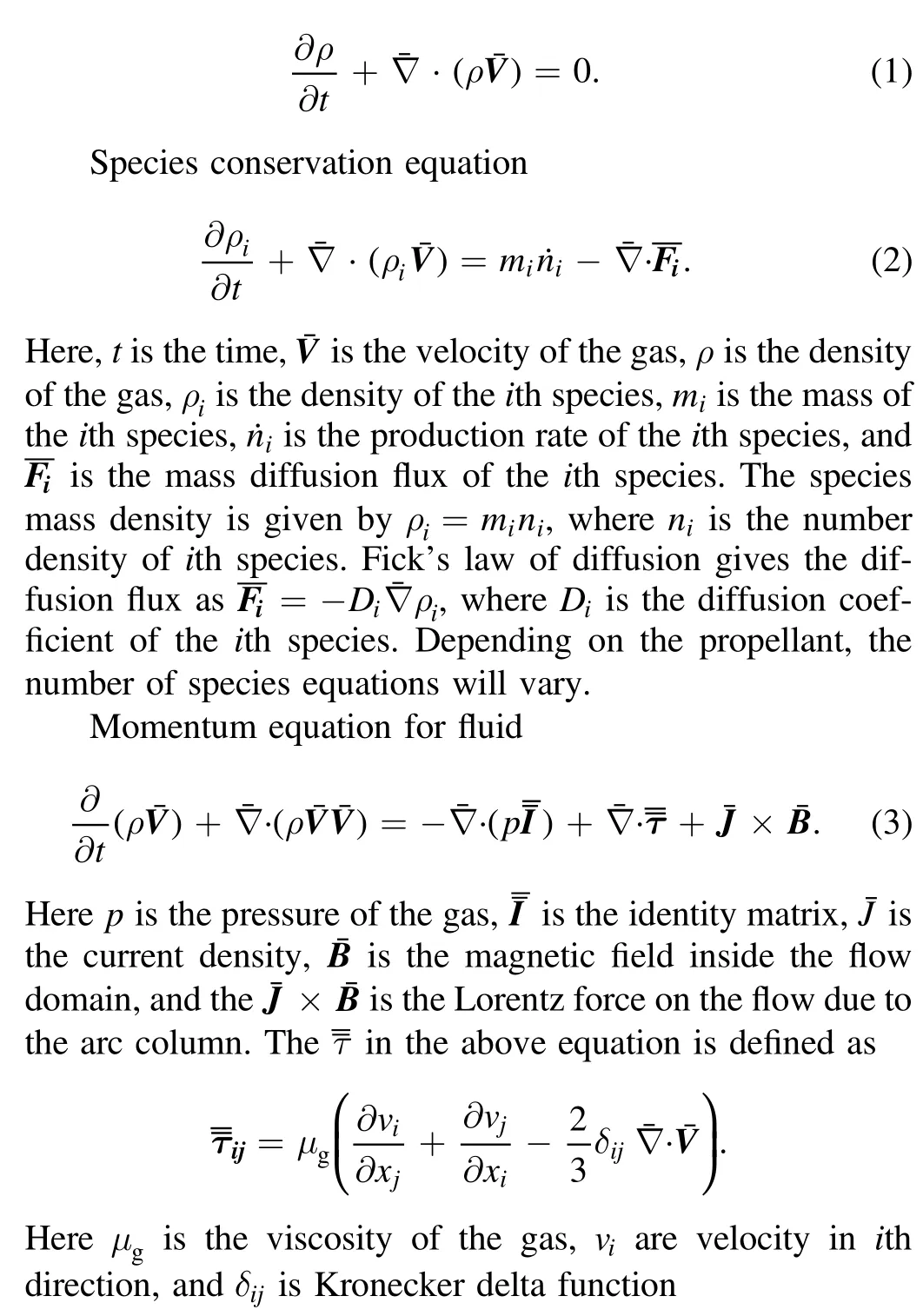
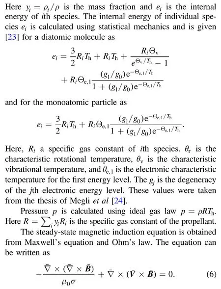
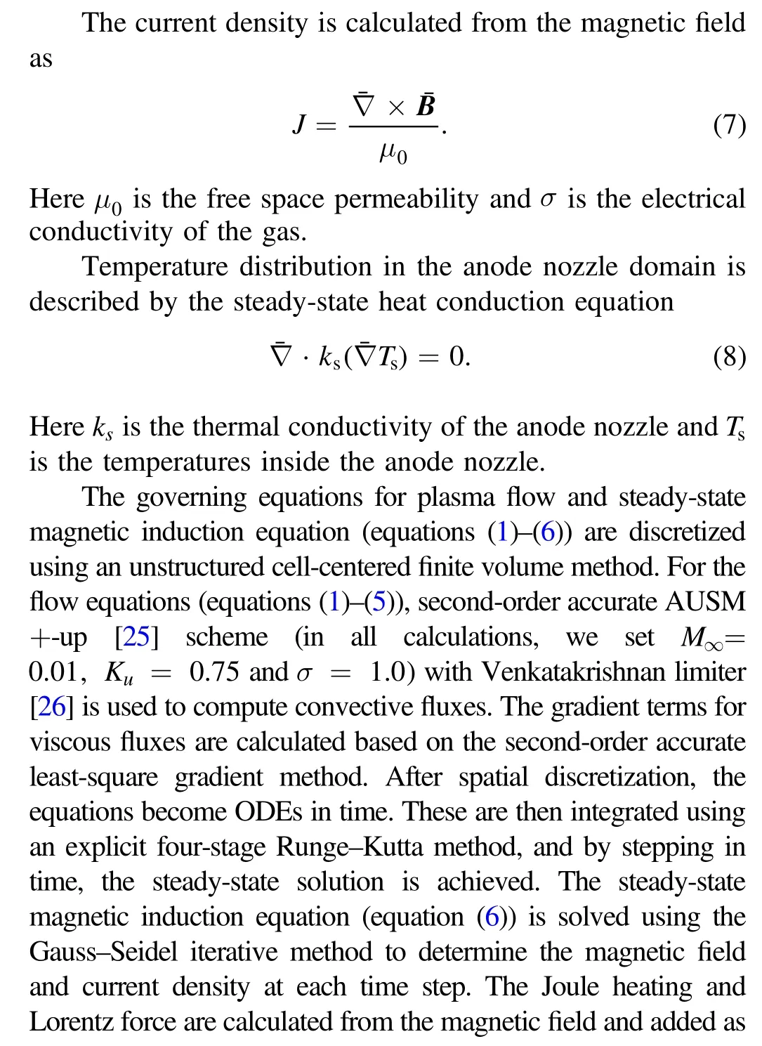
The set of governing equations for solving plasma includes conservation equations of mass,species,momentum,and energy for viscous,compressible flow with the Lorentz forces and Joule(Ohmic)heating as source terms in momentum and energy equations,respectively.The temperature in the anode nozzle domain is solved using a steady-state heat conduction equation 2D steady-state Maxwell’s equations combined with Ohm’s law(neglecting Hall effect and ion slip)and Ampere’s law(neglecting displacement current)give the magnetic induction equation used to obtain the magnetic field inside the plasma.The other electromagnetic variables are calculated from the computed magnetic field.The complete set of governing equations along with the sheath model are presented next in order.
Mass conservation equation for fluid.


2.3.Chemical reactions


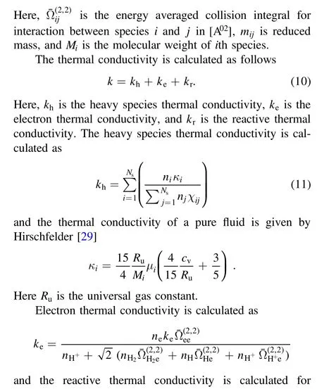
2.4.Thermodynamics and transport properties



2.5.Sheath model
The electrons having higher mobility get absorbed by the walls,charging the surface negative relative to the bulk plasma and leaving behind a net positive charge within the Debye length from the wall.This positive charge region near the electrode walls is the plasma sheath.The arcjet models,which ignore the plasma sheath effect,underestimated the voltage/operating power.However,calculating sheath voltage is cumbersome,and including it in the primary model considerably slows down the simulation.Therefore,some arcjet models[19,36,37]either ignore the sheath effect or assume some sheath potential.Megliet al[11]assumed a total sheath voltage fall of 13 V,and Milleret al[10]took cathode voltage drop equal to the ionization potential plus one-half of the dissociation potential of the gas.Others like Fujitaet al[14]and Luet al[12]calculated electrode sheath voltage at the cathode surface by solving current density balance and heat flux balance equations with a third equation that assumes ion current towards cathode at the sheath edge is equal to the ambipolar diffusion flux from the plasma.
A simplified sheath model,inspired by previous work of Fujitaet al[14],Luet al[12],Messaadet al[16],and Lunet al[17],is considered in this study.The model presented in the literature[12,14,16]assumes the net heat flux to the cathode to be zero.However,in reality,a considerable amount of heat is conducted to the cathode to be transferred again to the propellant upstream.Therefore,in the present model,instead of solving the heat flux balance equation,which assumes net heat flux to be zero at the cathode surface,the heat generated is redistributed in the sheath to upstream flow through cathode surface by conduction.For obtaining the sheath potential,current density balance at the cathode surface(equation(17))is solved.
The sheath model is simple and two-way coupled with the primary arcjet model and adequately complete to capture essential sheath physics effects.A decoupled model predicts the operating voltage,but the energy added due to sheath to bulk plasma in the arcjet is not accounted for,which leads to an error in correctly predicting the energy distribution.It is assumed that the arc attaches at the cathode spot over an areaAswith uniform current density.The current conducted comprises of three components,namely current density due to ion diffusion towards the cathode(jid),electron current density due to the electrons with enough directed thermal energy moving from the bulk plasma towards the cathode(jth),and electron current density due to the thermofield emission of electrons from the cathode spot area(jem).The current density balance at the cathode sheath can be written as
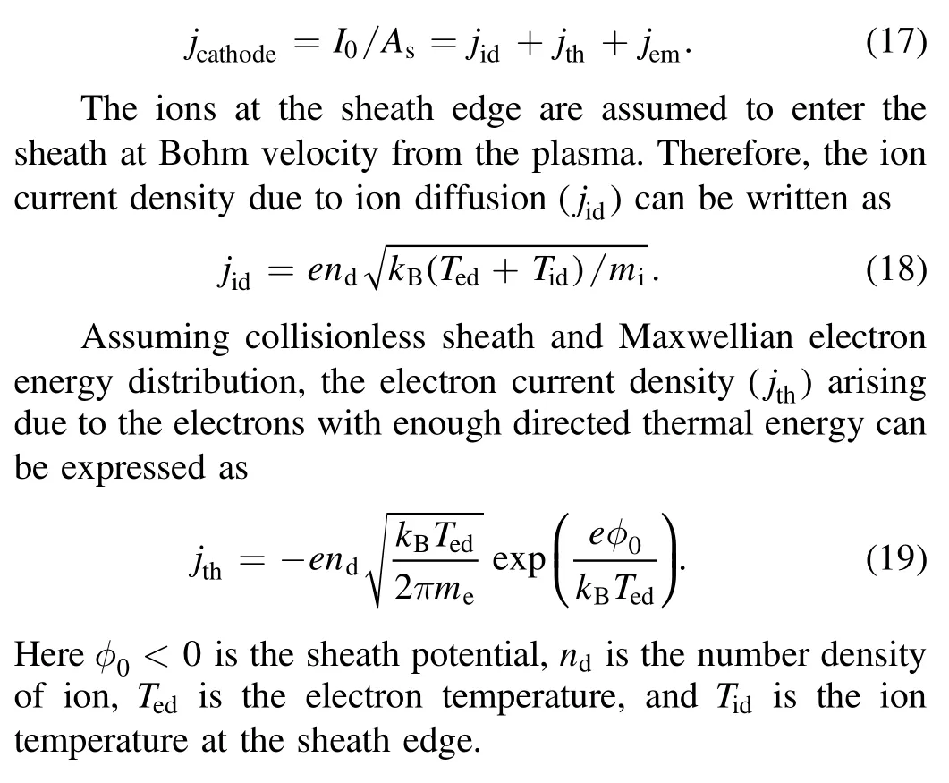
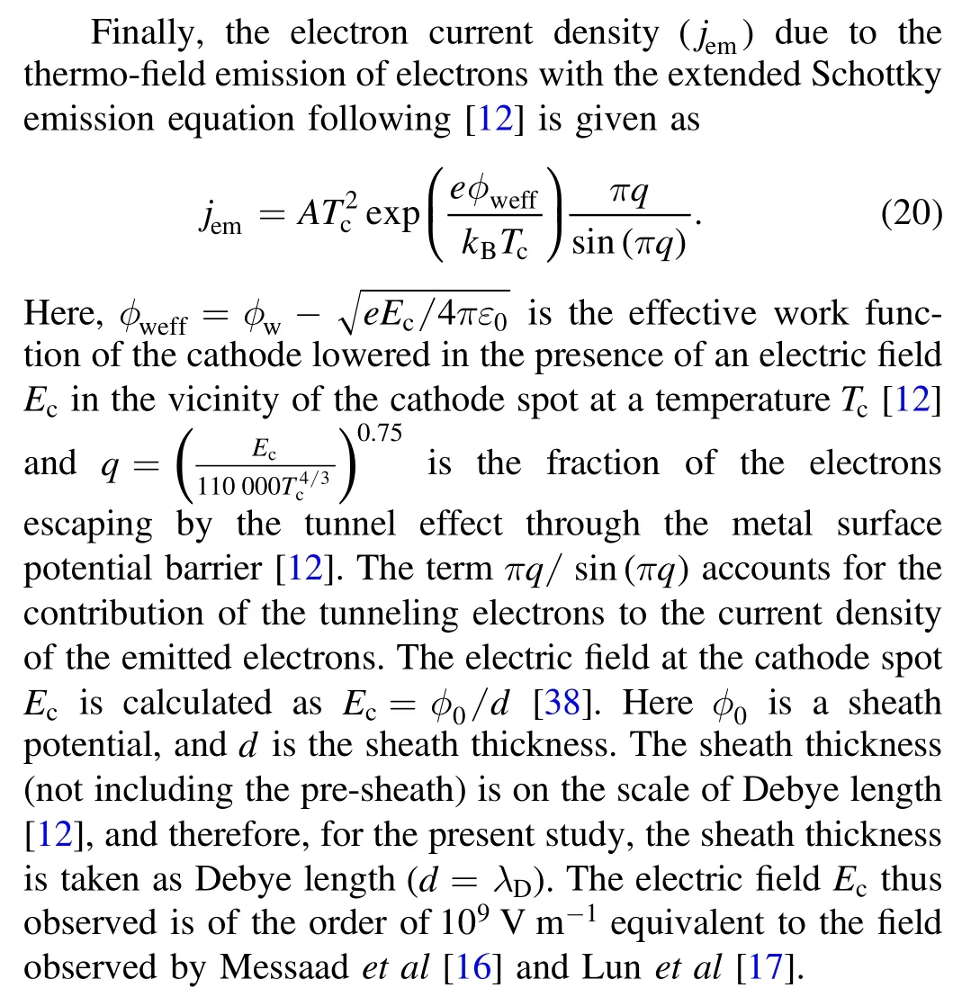
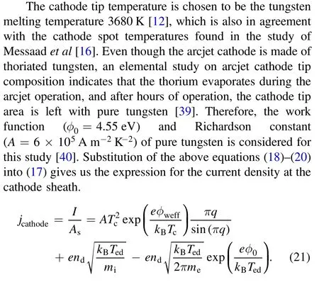
The number density of ion(nd)and electron temperature(Ted)at the sheath edge are taken from the simulation and are values of the finite volume cell immediately next to the cathode tip.
The model requires the cathode spot area(As),over which the current attaches the cathode.The study conducted by Harriset al[42]on cathode erosion suggests that the arc spot is nonstationary,expanding and/or moving around on the cathode tip at an undetermined frequency.Harriset al[42]reported two distinct surface features on the thoriated-tungsten cathodes:a central raised dimple surrounded by a larger melted region,and a single cathode spot was assumed to exist on the cathode dimple for arcjet cathodes operating in a diffuse discharge mode.Curran and Haag’s[43]found a crater of more than 0.8 mm diameter at the cathode tip of a 1.2 kW hydrazine arcjet thruster.Within the main crater on the tip,a second molten crater with a diameter of approximately 0.16 mm was present,the point of arc attachment during steady-state operation.The 0.16 mm crater corresponds to an attachment area of approximately 2 ×10⁻⁸m2.Moreover,Bearnset al[44]found the current density profile at cathode tip constricted in size when the mass flow rate is increased for a constant current and expanded in size when current is increased for constant mass flow rate.In the experiments on vacuum discharge with a copper cathode for a fixed current,Daalderet al[41]found craters with diameters varying over a wide range.For example,at4.7 A the crater diameter varies between 1 and 8μm.The experiments show a general shift to a larger value of crater diameter with an increase in arc current.A close examination of the crater diameter data for current less than40 A reviled the crater area increased logarithmically with the current,as can be seen in figure 1.Similar logarithmic trends were also observed in the model of Messaadet al[16].It is to be noted that in the experiments of Goodfellowet al[46],where current values were high,ranging from 600 to 1400 A,cathode operates under a different operating condition,the arc length seems to increase exponentially with current.Luet al[12]pointed out that the average current density estimation based on cathode spot area may be a good one for the high-power arcjet but a poor one for the low-power arcjet.Experimental data of Curranet al[45]on medium power arcjet shows the drop in the voltage increased by two-fold and in higher current input cases to more than threefold when the mass flow rate was dropped evenly from 21.2 to 16.1 mg s-1and further down to 11.2 mg s-1,as can be seen in figure 2.Such a drop in voltage with a decrease in mass flow rate must be accompanied by an exponential rise in the cathode spot area.Based on the preceding discussion,the cathode spot area was assumed to increase logarithmically with current and decrease exponentially with mass flow rate as

Ions and electrons in the sheath region get accelerated by the sheath potential.Ions moving towards the cathode enters the sheath with Bohm velocity.These ions further get accelerated in the sheath region to a higher velocity and,therefore,to higher kinetic energy.These high-energy ions impact the cathode,and energy generated gets deposited on the cathode surface.The thermofield electrons emitted by the cathode spot have thermal energy equivalent tokBTcand are further accelerated by the sheath potential.These high-energy electrons collide with heavy species and thereby heat the propellant near the cathode spot.On the other hand,the electrons diffusing towards the cathode get decelerated due to the sheath potential.Only very few electrons with high enough thermal energy reach the cathode.It is assumed that these diffusing electrons will get absorbed by the cathode.Therefore,the heat generated in the cathode sheath region can be given as

The study by Messaadet al[16]on the low current vacuum arc cathode region concluded that the spot radiation could be neglected with respect to the other cooling phenomena of the cathode.Therefore,for the present model,spot radiation has been neglected.The heat flux at the cathode surface is assumed to increase linearly from zero at the inlet starting point of the cathode to a maximum at the cathode tip.The maximum heat flux at the cathode tip is obtained such that heat flux integrated over the cathode surface area isQcat.Curranet al[46]found that the cathode energy losses were between 1%and 5%of the total input power.Therefore,the total heat deposited in the cathodesheath region(Qcat)is assumed to be conducted to the cathode and entirely distributed to flow in the inlet section of the arcjet.

Table 2.Boundary conditions at flow boundaries.
At the anode inner surface,as there is no thermofield emission,the equation(21)without the thermofield emission term is modified to equation(24)to obtain current density at the anode surface[10].

Note that the sign is reversed in equation(24)as the ions move in the opposite direction,and electrons move in the direction of current flow.As the current density at the anode does not exceed the random thermal flux of electrona potential well exists which repels excess electrons in random thermal flux.Therefore,this yields a voltage drop.Equation(24)can be rearranged to obtain sheath potential as

The anode sheath voltage comes out to be negative(~-1 V)for the operating conditions discussed in this study.This implies that the current at the anode is primarily due to electron diffusion,and the negative sheath voltage turns back the excess thermal flux of electrons beyond those required by the circuit[10,15].
2.6.Boundary condition
The simulations are carried on two separate computational domains,the flow domain and the anode nozzle domain.The two computational domains are shown in figure 3.The plasma flow and steady-state magnetic induction equations(equations(1)-(6))are solved in the flow domain,whereas the steady-state heat conduction equation(equation(8))is solved in the anode nozzle domain.
The plasma flow domain and the anode wall domain are solved alternately,and each provides boundary conditions for the other and a two-way coupling is established.Solution of plasma provides heat flux to the anode(see table 3)and solving heat equation in the anode wall provides interface temperature for the plasma.This process is repeated over several iterations to obtain a steady-state solution in both domains.The boundary conditions for the continuity,momentum,energy,and magnetic induction equation on the flow domain are summarized in table 2,and the boundary conditions on the anode nozzle domain are summarized in table 3.According to Megli[24],the radiation loss of optically thin plasma to the anode nozzle is less than 1% of the total input electrical power.Therefore,radiation loss from flow to the anode nozzle is neglected.
HereTambis the ambient temperature andTbgis the temperature of gas near the anode inner surface,εis the emissivity of the anode outer surface,σris the Stefan-Boltzmann constant,andαis the divergence angle.
3.Results and discussion
3.1.Model simulations
The flow part of the numerical model was initially validated against standard compressible benchmarks like CD nozzle flow[47].After that,the numerical model was used to simulate hydrogen arcjet thruster and validated by comparingthe numerical prediction with the experimental data available in the literature[48,49].

Table 3.Boundary conditions at anode nozzle boundary.
The thruster used for the validation is shown in figure 4.The tungsten nozzle has a 0.635 mm diameter,a 0.25 mm long constrictor,a conical(30 half-angle)convergent section,and a conical(20 half-angle)diverging section with an area ratio of 225(9.53 mm exit diameter).The thruster was operated with a mass flow rate of 13 mg s-1and 10.3 A input current.Figure 5 shows comparison of predicted radial profiles of axial velocity,temperature and electron number density with the experimental data[48,49].The comparison is reasonable.The inclusion of more complex chemical reactions,such as the formation ofandis expected to improve the electron number density prediction.These can be included in the future as improvements to the model.
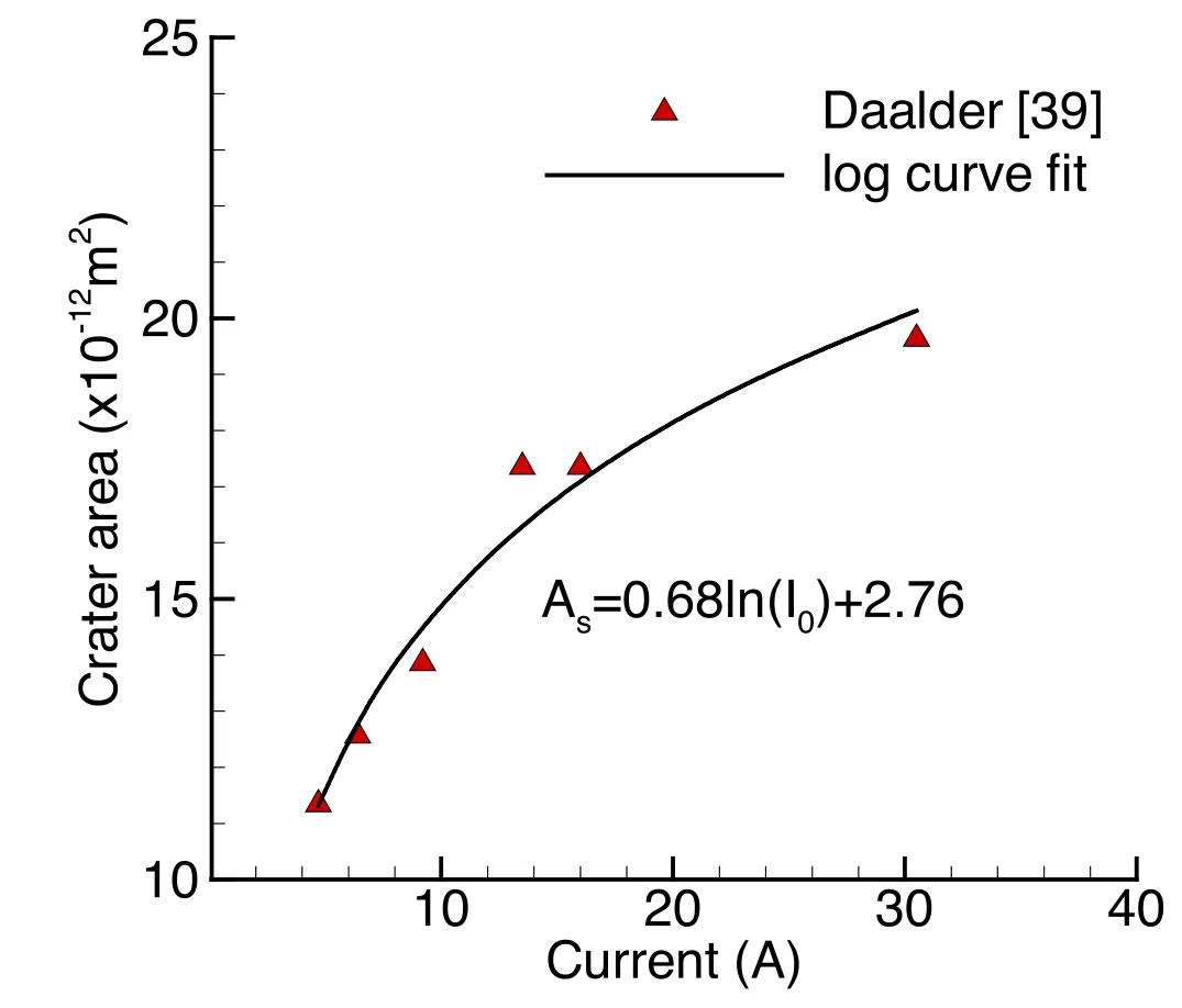
Figure 1.Variation of crater area on a copper cathode with current[41].

Figure A1.Variation of thermal conductivity of hydrogen plasma with temperature.Comparison of present model predictions with corresponding values from the literature[34].

Figure A2.Variation of electrical conductivity of hydrogen plasma with temperature.Comparison of present model predictions with corresponding values from the literature[34].
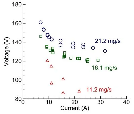
Figure 2.Current/voltage characteristics for different mass flow rates.
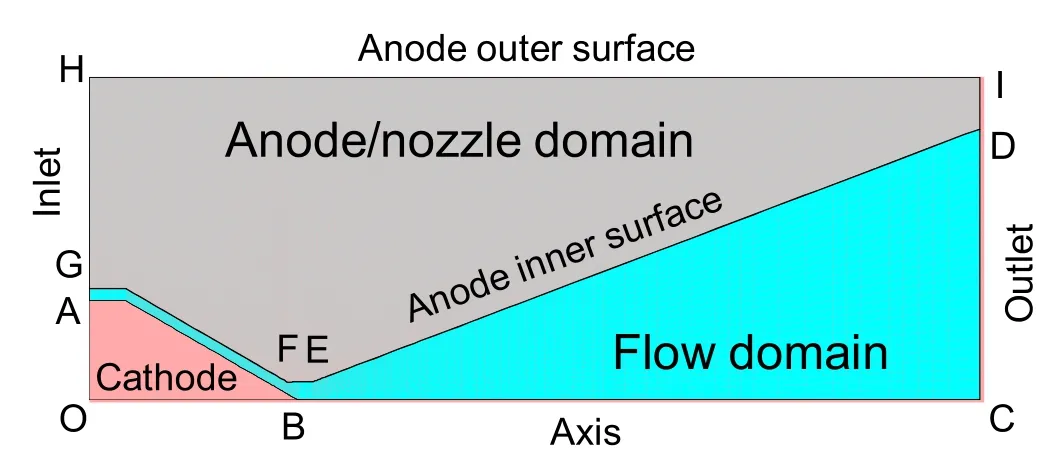
Figure 3.Schematic of the arcjet thruster showing computational domains(the flow domain and the anode nozzle domain)with boundaries.
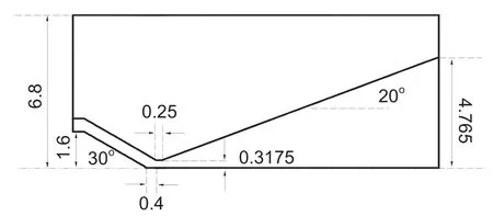
Figure 4.Arcjet thruster dimensions(in mm).
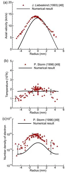
Figure 5.Comparison of axial velocity(a),temperature(b),and number density of electron(c)at the exit plane of hydrogen arcjet thruster with experimental data[48,49](m ˙=13 mg s-1,I=10.3 A).
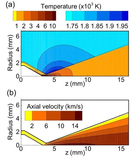
Figure 6.Contours of gas/plasma temperature and anode wall temperature(a),and gas axial velocity(b)inside arcjet thruster(m˙=13 mg s-1,I=10.3 A).

Figure 7.Variation of discretization error with minimum grid size.

Figure 8.Comparison of current/voltage characteristics with experimental data[45].
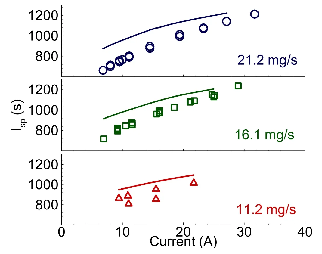
Figure 9.Comparison of specific impulse with experimental data[45].

Figure 10.Comparison of efficiency with experimental data[45].
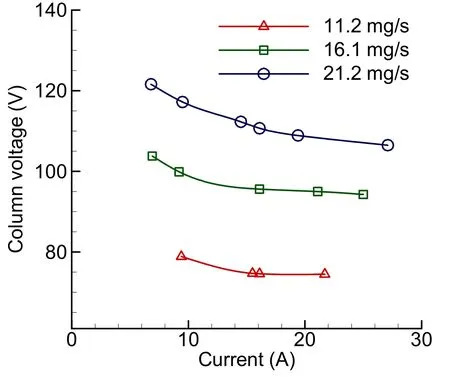
Figure 11.Variation of column voltage with currents for different mass flow rates.
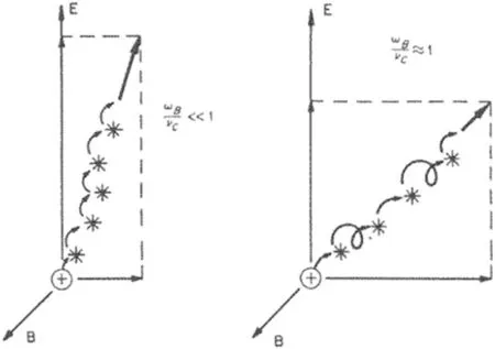
Figure 12.Mean charged-particle motion in crossed electric and magnetic field for various Hall parameters(Jahn[5],figure,5-5).

Figure 13.Variation of density along the radial direction at constrictor exit for different input currents at m˙=16.1 mg s-1.

Figure 14.Variation of density along the radial direction at constrictor exit for different mass flow rates at I=16.1 A.
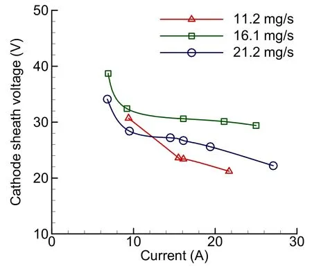
Figure 15.Variation of cathode sheath voltage with currents for different mass flow rates.

Figure 16.Variation of the percentage of input power added by the cathode sheath with currents for different mass flow rates.
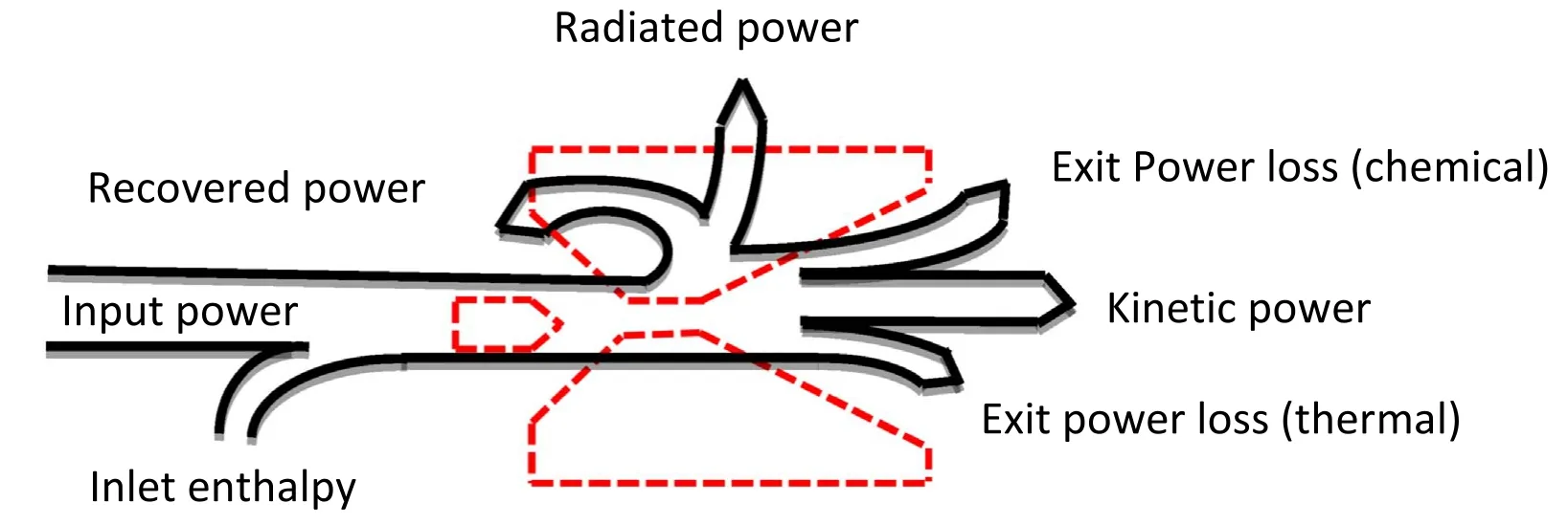
Figure 17.Schematic illustrating various power losses in an arcjet thruster.

Figure 18.Variation of power distribution with the current for m˙=16.1 mg s-1.
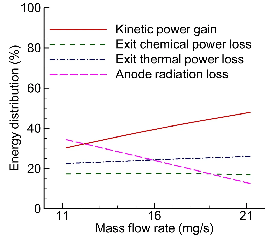
Figure 19.Variation of power distribution with mass flow rate for I=16.1 A.

Figure 20.Variation of components of input current at cathode spot with the input current for different mass flow rates.
The contours for the temperature and velocity inside the arcjet obtained from the simulation are presented in figure 6.As can be seen from figure 6(a),the temperatures inside the flow domain are high inside the constrictor as the primary deposition of energy due to arc happens in the region of the constrictor.The temperature drops as the high enthalpy flow in the constrictor gets converted to high-velocity flow(figure 6(b))after passing through the divergent section of the arcjet.The arc attaches to the anode wall downstream of the constrictor,resulting in a high heat flux at the arc attachment point.Therefore,temperatures are high in the anode domain downstream of the constrictor(figure 6(a)).The temperature variation is not very high in the anode domain as the thermal conductivity is very high for the tungsten.Some amount of heat gets back to the flow from the anode domain,resulting in a rise in temperature near the anode wall in the convergent section.
Furthermore,the operating powers for various operating conditions predicted by the model were cross-examined with the experimental data reported by Curranet al[45].Curranet al[45]performed an experimental investigation to evaluate hydrogen arcjet operating characteristics in the range of 1-4 kW on a series of nozzles.The operating power reported by Curranet al[45]on nozzle insert-1 geometry was used to examine the present model as nozzle insert-1 geometry was operated over the broadest range of test conditions.A gridindependence study was performed on the geometry of nozzle insert-1 prior to cross-validation of operating powers.
3.2.Grid independence study
Grid independence study was performed on three meshes with 1092,4175,16317 number of elements in the flow domain(minimum cell sizes of 25.4,12.7,and 6.3 μm in the constrictor region)and with 1314,5006,19 530 number of elements in the anode nozzle domain,respectively.The sheath model calculation takes the electron temperature in the cell neighbor to the cathode tip as the electron temperature at the sheath edge.The simulations are conducted with a pointed cathode tip.As the grid is refined,the current density near the cathode tip rises due to the pointed cathode tip,which is not the actual case,resulting in a rise in electron temperature.This dependency of local electron temperature in the neighboring cell of the cathode tip on the grid leads to an error in sheath potential and,therefore,the operating voltage when the grid is changed.The grid independence studies are conducted on a global variable,whereas the sheath potential depends on a local variable.Therefore,for the grid independence study,the only voltage obtained in simulation excluding the sheath voltage is considered,i.e.the column voltage.The column voltage is obtained for hydrogen thruster operating at a mass flow rate of 16.1 mg s-1and 16.1 A input current on these three meshes.
The Richardson extrapolation procedure[50]is used to obtain the column voltage extrapolated to zero mesh size,assuming a single dominant error term of order ƥ,where ƥ is observed order of convergence.The grid independence study results are summarized in figure 7,where the variation of discretization error of column voltage on all three grids is plotted(log-log plot)against the mesh size.The observed order of convergence for column voltage is found to be 2.8.The discretization error for the grid with 4175 elements in the flow domain and with 5006 elements in the anode nozzle domain is less than 0.5%,and therefore,the grid was selected to conduct further studies.
3.3.Arcjet thruster performance prediction
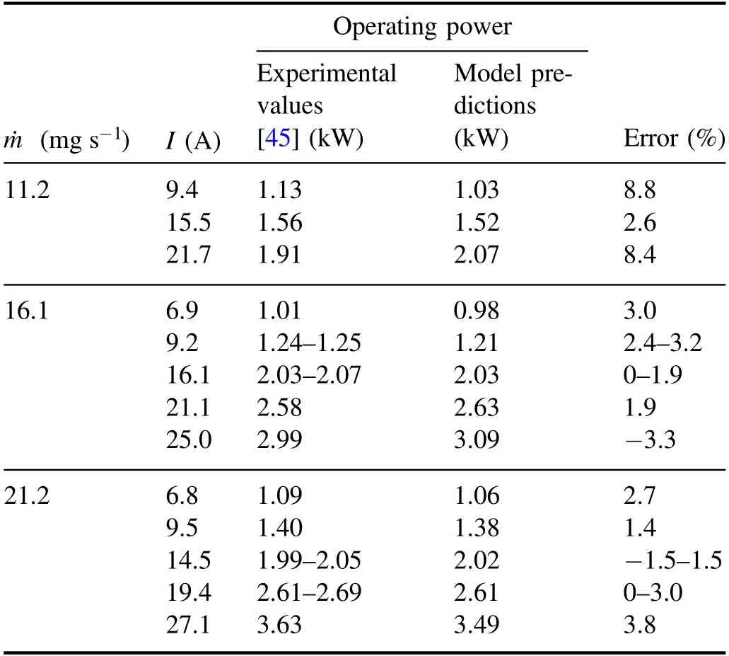
Table 4.Comparison of the predicted operating power with experimental values.
The values of operating power obtained in the work of Curranet al[45]for nozzle insert-1 are compared with the model predictions in table 4.The comparison of current-voltage characteristics is plotted in figure 8.The predicted operating power and voltage values for a mass flow rate of 16.1 and 21.2 mg s-1for various current values are seen to be within 4% error.However,for a low mass flow rate(11.2 mg s-1),errors are somewhat larger.This could be due to a marked decrease in thruster stability observed in the experiments[45].The fluctuation in experimental voltage data was more than 14 V,as can be noted in figure 8.
The authors of[45]attributed fluctuation to damage in the form of melting in the constrictor regions of the anode and also to dynamic arc characteristics.Post-test measurements revealed constrictor diameter had increased from 0.61 mm to approximately 0.71 mm,and the arc gap increased by as much as 0.13 mm in some cases.Luet al[12]estimated that cathode erosion might yield an additional 3-5 V to the plasma voltage because the arc length increases as the cathode tip recede.The erosion effect is not accounted for in the present arcjet model,which may lead to higher uncertainties in voltage predictions.It is quite likely that the constrictor diameter may have increased to 0.7 mm for the propellant low mass flow rate of 11.2 mg s-1due to the arc attachment at the anode closer to the constrictor exit,hence causing erosion and fall in voltage.Therefore,the voltage predicted by the model for the mass flow rate of 11.2 mg s-1is higher than the value observed in experiments.Considering the experimental uncertainties,the total voltage prediction agrees quite well with the experimental values.Even though the sheath model was calibrated to operate on nozzle insert-1 geometry with a constrictor diameter of 0.61 mm,the model performed very well on geometry with a different constrictor diameter of 0.635 mm,discussed in the Model validation section.
The upstream walls of electrodes are normally assumed to be adiabatic in an attempt to isolate the thruster from the rest of the assembly.However,in an actual scenario,some amount of heat is transferred by conduction from the hot anode nozzle to other parts of the system[1].The assumption of adiabatic upstream walls results in the amount of energy that should have been lost to be conducted back into the flow.Furthermore,the model neglects the radiation loss from the plasma.These are possible reasons that explain the overprediction of thrust and specific impulses by the model.The predicted specific impulse and the corresponding experimental values can be seen in figure 9.The predicted specific impulse is 5%-30% higher than the experimental value,follows the trend observed in the experiments.Larger deviations are observed for low current operations.
There is a mismatch between the formula reported by Curran for the calculation of efficiency and the data presented in table 2 of the literature[45].Therefore,the authors of this research paper recalculated the efficiency using the expression presented in the literature[45]

The comparison of computed efficiency from the present model and the recalculated efficiency from the literature is shown in figure 10.The efficiencies are over predicted,especially for lower currents.The specific impulse was overpredicted higher for lower current,and the efficiency expression varies quadratically with the specific impulse.Therefore,predicted efficiencies for lower currents show a larger deviation.This could be due to the underprediction of energy losses for lower currents.
3.4.Arc column voltage
The column voltage is the voltage across the arc without sheath and is shown in figure 11.The column voltage increases with an increase in mass flow rate and decreases slightly with an increase in input current.The variation in column voltage is primarily due to arc dynamics.With an increase in the mass flow rate,the arc attachment point on the anode moves downstream,making the arc longer,therefore increases the column voltage.On the other hand,with an increase in input current,the arc attachment point on the anode shifted slightly upstream,reducing the arc length and,therefore,slightly reducing column voltage.
In the simulations,the Hall parameter for electronswas found to be very small near the constrictor region.HereωBis the gyro frequency andνcis the collision frequency of electrons.The low Hall parameter implies that the collision phenomenon is dominant,and therefore,electrons move dominantly in the direction of the electric field instead of theE×Bdirection[5],as can be seen in figure 12.The phenomenon of diffusion of electrons from the arc column to the anode inner surface is guided by the radial component of the electric field.The speed by which the electrons diffuse depends predominantly on the electron mobility(or electron diffusion coefficient)in the surrounding gas,and it will determine the arc attachment point.The mobility is given aswhere collision frequency isis the thermal velocity of electrons.Therefore,electron mobility can be expressed as

This equation(27)can be interpreted as more density causes more number of collisions,thereby reducing the electron mobility.When an input current increases at a constant mass flow rate,the propellant’s specific energy increases,which results in an increase in the velocity of the propellant.As the mass flow rate should remain constant,the density decreases in the constrictor region,as seen in figure 13.It can be seen from equation(27)that the mobility increases as density decreases.This increase in mobility enhances electron diffusion towards the inner surface of the anode,which shifts the arc attachment point upstream and reduces the arc length.An increase in temperature with an increase in input current slightly counters the reduction of arc length.Therefore,with an increase in input current,there is a slight reduction in arc length.On the other hand,when mass flow rate increases with constant input current,the density increases in the constrictor region,as seen in figure 14,while the temperature changes slightly.The higher density reduces the mobility and slowdowns the process of electron diffusion towards the inner surface of the anode,thereby shifting the arc attachment point downstream and increasing the arc length.
3.5.Cathode sheath
The sheath voltages at the anode were found to be around-1 V,also the case for Lunet al[19],which is insignificant in comparison with the operating voltage.However,the sheath voltages at the cathode were found to be around 20-40 V.The cathode sheath voltage for the various operating condition is shown in figure 15.The cathode sheath voltage was found to decrease with the current,primarily due to an increase in the cathode spot area.It is interesting to note that the cathode sheath voltage increased when the mass flow rate was raised from 11.2 to 16.1 mg s-1but decreased when the mass flow rate was raised to 21.2 mg s-1.
The variation of the cathode sheath energy input fraction in operating power is plotted for the various operating conditions in figure 16.The plot shows that the cathode sheath energy input fraction in operating power decreased with an increase in input current.One can note from figure 16 that a higher percentage of energy gets added by the arc inside the flow for high mass flow rates and input currents.Therefore,arcjets operating at high mass flow rates and input currents are expected to deliver a better performance.On the other hand,a considerable fraction of energy will be deposited in the cathode sheath region for lower mass flow rates and currents.
3.6.Power distribution and losses
In a typical arcjet,the electrical energy(input power)is added to the flow by an arc,and a small part of enthalpy comes with the inlet flow(inlet enthalpy).The arc heats the flow and raises the temperature through the process of collisions between the ions in the arc column and gas particles in the constrictor region,called Joule heating.The electrical energy supplied to the arcjet increases the flow velocity by converting itself into kinetic energy.Simultaneously,the supplied energy also gets converted to various other forms of energy,leading to losses.The energy added to the propellant through the arc in the constrictor region raises the enthalpy of flow.A portion of power added to the propellant gets conducted to the anode through its inner surface,of which a fraction of energy is given back to the propellant in the early part of the convergent section as regenerative heating of propellant,and the rest gets radiated to space as radiation loss.After the expansion process,some part of the enthalpy gets converted to useful kinetic energy,while the rest exits the thruster with propellant,resulting in exit thermal losses.Some part of Joule heating is used to break the bonds and ionize the propellant to assist the flow of the arc.During expansion through the divergent section,the temperature drops,resulting in recombination reactions.Due to the decrease in pressure,thus reaction rate,and limited length of the thruster,a fraction of ions and atoms exit the thruster without recombining,resulting in exit chemical losses.A small fraction of flow kinetic energy whose velocity is in the radial direction is lost as it does not take part in thrust generation called divergence loss.All these losses combine to restrict the overall thrust efficiency of the arcjet thruster to around 30%-40%.Schematic illustrating various power losses in an arcjet thruster is shown in figure 17.The schematic illustrates various power losses similar to figure 18 of Wollenhauptet al[8];however,the losses have been categorized somewhat differently in the present study.
The various components of energy distribution with the current for 16.1 mg s-1mass flow rate are shown in figure 18.As the current is increased for a particular mass flow rate,the specific energy of the propellant raises,thus increasing the propellant temperature.The rise in temperature with an increase in input current in the constrictor region causes a rise in the fraction of energy conducted to the anode from 0.18 for 6.9 A current to 0.33 for 25 A current.Whereas the regenerative heating fraction remains nearly constant around 0.07-0.08 for all currents due to the low thermal conductivity of the propellant,leading to higher anode radiation loss with an increase in current.The rise in temperature with an increase in input current also leads to a higher fraction of dissociation and ionization reaction,resulting in higher chemical power losses with the rise in input current.However,it is interesting to note that the fraction of exit thermal power loss drops with the rise in current.The overall fraction of loss increases with an increase in input current,which results in a lower kinetic energy gain for flow,thus a drop in the thrust efficiency.The above-discussed trends can be observed in figure 18 for the mass flow rate of 16.1 mg s-1.Loss in the efficiency of the thruster with an increase in current is mainly due to an increase in anode radiation loss.
The various energy distribution components with the mass flow rate for 16.1 A current are shown in figure 19.Interestingly,only anode radiation losses fraction reduced with an increase in mass flow rate as the arc diameter became smaller,reducing the temperature of the flow near the anode inner surface and,therefore,the heat flux to the anode.The arc had also moved downstream for a higher mass flow rate.The presence of arc in the downstream region leads to the addition of heat to flow far downstream,therefore increasing both fractions of exit thermal and chemical power losses.However,the variation in both fractions of exit thermal and chemical losses is slight.The reduction in radiation loss fraction increased the fraction of energy associated with kinetic energy,improving efficiency.
3.7.Cathode current distribution
The current distribution at the cathode tip for the current sheath model is discussed in this section.The model accounts for thermofield emission,and the current due to it was found to be relatively constant for all operating conditions around 3.6-5.4 A.The relatively constant thermofield emission current may be due to assuming a constant temperature at the cathode.Nevertheless,the result may not be very far from the actual case as the Messaadet al[16]showed the temperature changed only by 200 K for the current changing from 10 to 30 A.Luet al[12]as well pointed out that the increase of the cathode tip temperature did not affect the overall results significantly.The thermofield emission current slightly increased due to a change in an electric field at the cathode tip with the current.The currents due to electrons diffusing towards the cathode were negligible due to high barrier sheat potential,which is also consistent with the results of Luet al[12].Therefore,the rest of the current is conducted by the ions diffusing towards the cathode.The input current components at the cathode tip are plotted in figure 20.As the thermofield emission currents are relatively constant and currents due to electrons diffusing towards the cathode are negligible,the ion diffusion current varies proportionally with the current.It is interesting to note that the increase in current due to ions diffusing towards the cathode increases while the cathode sheath potential drops with an increase in input current.This is mainly due to the rise in the number density of ions near the cathode spot with a rise in input current.
4.Conclusion
A 2D axisymmetric thermal and chemical non-equilibrium model of arcjet thruster was developed.The model incorporates one equation sheath model(both at anode and cathode),which is two-way coupled with the plasma flow.The model also solves heat conduction in the anode nozzle wall.The model successfully predicted operating voltage for a range of operating conditions of propellant mass flow rate and input current.The model also reasonably predicted the specific impulse and efficiency.However,the values were somewhat over those predicted at low currents.The following conclusion may be drawn from this study.
1.For a hydrogen arcjet[45]operating over a range mass flow rate of 11.2-21.2 mg s-1and input current range of 10-30 A,the anode sheath voltages are found to be negligible(around -1 V),and the cathode sheath voltages varied from 20 to 40 V.The cathode sheath voltage decreased with an increase in input current.Whereas for an increase in mass flow rate,the cathode sheath voltage showed a non-monotonic behavior.The model can be applied to other thruster geometries once the arc area attachment equation is calibrated.
2.Variation in mass flow rate or current influences propellant density in the constrictor and thereby the arc.Higher propellant mass flow rate leads to higher density in the constrictor region,slowdowns the electron diffusion,thereby causing an increase in arc length.On the other hand,an increase in current decreases density in constrictor and hence decreases arc length.
3.A parametric study on the variation of power distribution with operating conditions(input current and propellant mass flow rate)was carried out.With an increase in input current,the anode radiation loss and exit chemical loss increased,and thermal loss decreased.With an increase in mass flow rate,anode radiation loss reduces while thermal and chemical losses remained nearly constant.
4.The anode radiation loss seems to be the main factor responsible for the variation of thrust efficiency.The drop in anode radiation loss mainly results in a rise in thrust efficiency with an increase in mass flow rate and lower input currents.Thrusters operating at high efficiencies were noted to have a longer arc length.
5.Of the three current components at the cathode tip,current due to electrons diffusing towards the cathode is negligible due to high barrier sheath potential.The curves for current due to ion diffusion and thermo-field electron emission show a cross-over at low input current value.Interestingly at low input current,the current at cathode is primarily due to thermo-field electron emission,while at higher currents,cathode current primarily comprises ion diffusion current.The current due to thermo-field electron emission is nearly constant at all operating conditions owing to near melting temperature at cathode spot.
Acknowledgments
This work was supported by the Indian Space Research Organization(VSSC under grants ASE1415160ISROAMIK and ASE1718174ISROAMIK).The authors are particularly grateful for the assistance given by Shri Pedda Peraiah C,who provided insight and expertise that greatly assisted the research.
Appendix
The transport properties are important for obtaining accurate numerical simulations.Of these,the thermal conductivity and electrical conductivity of hydrogen plasma are critical for accurate simulation of physical processes in an arcjet.It was ensured that all the properties used in the present simulations are consistent with the data available in the literature.The variation of thermal conductivity(see figure A1)and electrical conductivity(see figure A2)of hydrogen gas/plasma with temperature obtained in the present model is plotted and compared with data from literature[34]up to the temperature of 30 000 K.
杂志排行
Plasma Science and Technology的其它文章
- Investigation of short-channel design on performance optimization effect of Hall thruster with large height-radius ratio
- Multi-layer structure formation of relativistic electron beams in plasmas
- Mode structure symmetry breaking of reversed shear Alfvén eigenmodes and its impact on the generation of parallel velocity asymmetries in energetic particle distribution
- Interaction between energetic-ions and internal kink modes in a weak shear tokamak plasma
- Investigation of the compact torus plasma motion in the KTX-CTI device based on circuit analyses
- Anomalous transport driven by ion temperature gradient instability in an anisotropic deuterium-tritium plasma
