Design of Wireless Power Transfer with High Efficiency for Biomedical Implants
2022-03-03QingyaLiZhiweiZhangJingnaMao
Qingya Li,Zhiwei Zhang,Jingna Mao
Abstract:Wireless power transfer (WPT) technology is a popular choice for biomedical implant devices.The demands of higher efficiency and smaller implantation size are hard to compromise in previous studies.In the present work,an implantable magnetic coupling resonant WPT system integrated with a metasurface element working at 430 MHz is presented.Similar planar copper coil components for the transmitting and receiving structures are used to construct the primary system,and then the metasurface element is integrated to constitute the whole WPT system.The effects of the distances between the transmitting coil and skin surface,between the skin surface,and receiving coil are discussed.The results show that the efficiency will be enhanced by 38–50 dB integrating with the metasurface.
Keywords:wireless power transfer (WPT);miniaturization;metasurface
1 Introduction
With the rapid development and enhancement of healthcare technology,a requirement has been risen for compact and efficient wireless implantable medical devices (IMDs) to monitor specific physiological properties. As a particularly important part of the device,power delivery needs to be considered.Conventional batteries or wired connections carry health risks and damage human tissues,which bring great pain and danger to patients.Accordingly,wireless power transfer(WPT) technology has emerged,which is a suitable approach to alleviate the suffering of patients and enhance healthcare safety [1].
Generally,a complete WPT system contains three major parts:a transmitter (TX),a wireless power link,and a receiver (RX),each of which has an important effect on the system power transmission efficiency (PTE).The complexity of human tissue increases the difficulties for accurately characterizing an implantable WPT system,which requires better matching behavior to achieve high transfer efficiency.In most applications,near-field inductive or magnetic resonance coupling techniques are extensively responsible for WPT systems [2−6],which widely use resonant coils to achieve the power transfer at a certain frequency,such as 13.6 MHz [2],40.68 MHz [3],403 MHz [4],400 MHz [5],1.9 GHz[6].Based on a previous study,the WPT system integrated with metamaterials for IMD applications was proposed,for which the insertion of the metasurface between the TX and RX coils was analyzed to improve efficiency.The effects of different parameters such as configuration,operating frequencies,and dimensions,on the PTE of the WPT system were explored [7].To optimize the misalignment performance,a four-resonator scheme was proposed,and excellent tolerance concerning lateral misalignment was achieved [8].
Recently,dual-band implanted antennas with single feed or differential feed methods were reported to support power transfer and radio frequency (RF) transmission capabilities simultaneously [9−10]. The low-frequency band can be used for WPT,and the high-frequency band is used for communication and data telemetry;for example,the WPT at 39.86 MHz,and the communication at 2.45 GHz in [9],the WPT at 915 MHz,and the communication at 1900 MHz in [10].However,research is focused on antenna design,and wireless links for implantable devices need to be further studied.When the implantable RX part is small,the transfer efficiency will dramatically decrease at a short distance.Moreover,human tissue also has an impact on transfer efficiency.Therefore,it is necessary to enhance the performance of wireless links for biomedical implants.The metasurface over the human body was proposed to improve the transfer efficiency in [11−13],which is used to achieve a longer transfer distance and more flexible adaptation.The aforementioned works showed a certain improvement in efficiency,but the size of the implantable element was slightly large. In this work,the size of the implantation element was minimized,and the efficiency of the WPT system was improved.
The rest of this article is organized as follows.Section 2 introduces the details of the proposed WPT system including transmitting and receiving elements.In section 3,the results and discussions are presented about the performance of the WPT system,and the metasurface is proposed and analyzed to improve the transfer efficiency.Section 4 concludes this work.
2 Designed Structure of WPT System
In this section,the proposed WPT system configuration of the external TX coil and implantable RX coil is presented.Additionally,the construction of the WPT link by utilizing the designed TX and RX elements is discussed.
2.1 TX Design
Fig.1 (a)-(c) shows the detailed geometry of an external TX coil,which is fabricated on the FR4 substrate with a relative dielectric constant of 4.4 and a loss tangent of 0.02.The dimension of the TX coil is 50 mm × 50 mm × 0.025 mm.Fullwave simulation software is adopted to simulate and analyze the performance of the whole WPT system. It is composed of a three-turn planar copper coil with gaps of 2 mm and 1.45 mm between the outer and middle turns,and the middle and inner turns,respectively.The widths of the outer,middle,and inner turns are 3 mm,3 mm,and 1 mm,respectively.A feeding line is printed on the back of the substrate,which is shorted with the other ends of the outer turn and inner turn via the shorting pins.The TX coil is excited through a 50 Ω coaxial feed port with resonance at 430 MHz.The reflection coefficient results of the TX elements are shown in Fig.2.S11is approximately –23 dB at a frequency of 430 MHz.
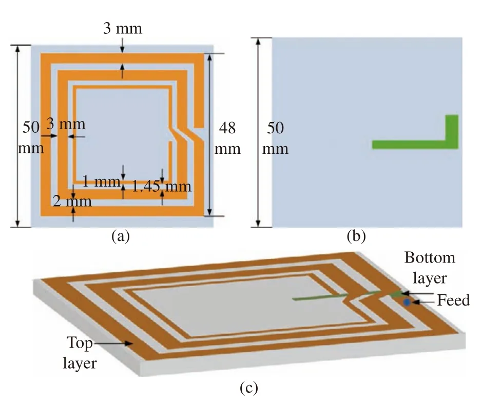
Fig.1 TX coil geometry:(a) top view;(b) bottom view;(c)whole configuration
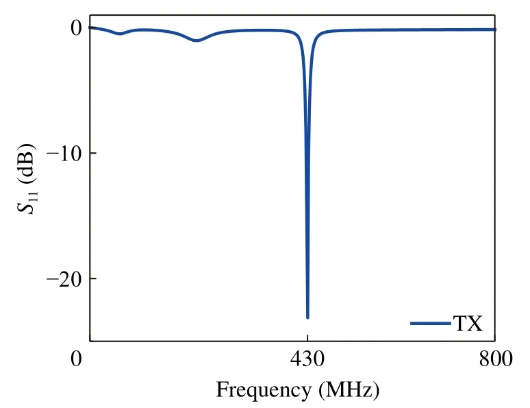
Fig.2 Reflection coefficient of the transmitting coil
2.2 RX Design
Fig.3 (a)-(b) depicts the detailed top view geometry of the RX coil,which is implemented on two layers of the FR4 substrate.The top layer of the RX coil consists of a four-turn planar copper coil with uniform widths and gaps of 0.41 mm and 0.12 mm between each other’s coils.When the top layer is rotated clockwise 90°,the bottom layer is acquired.The bottom layer has an identical structure and size to the top layer.The top and bottom layers constitute the RX coil,which resonates at 430 MHz.The dimensions of the RX element are 5 mm × 5 mm × 0.025 mm,which will be implanted into human tissue.Typical human tissue contains three layers,skin,fat,and muscle,with thicknesses of 1.0 mm,3.1 mm,and 16.1 mm,respectively [14],which are usually employed to simulate the partial human body environment.The dielectric properties of skin,fat,and muscle are fully frequency-dependent,and their permittivity and electrical conductivity at 430 MHz are shown in Tab.1 [15].Fig.4 presents the reflection coefficient of the RX element.S11is approximately–29 dB at a frequency of 430 MHz.
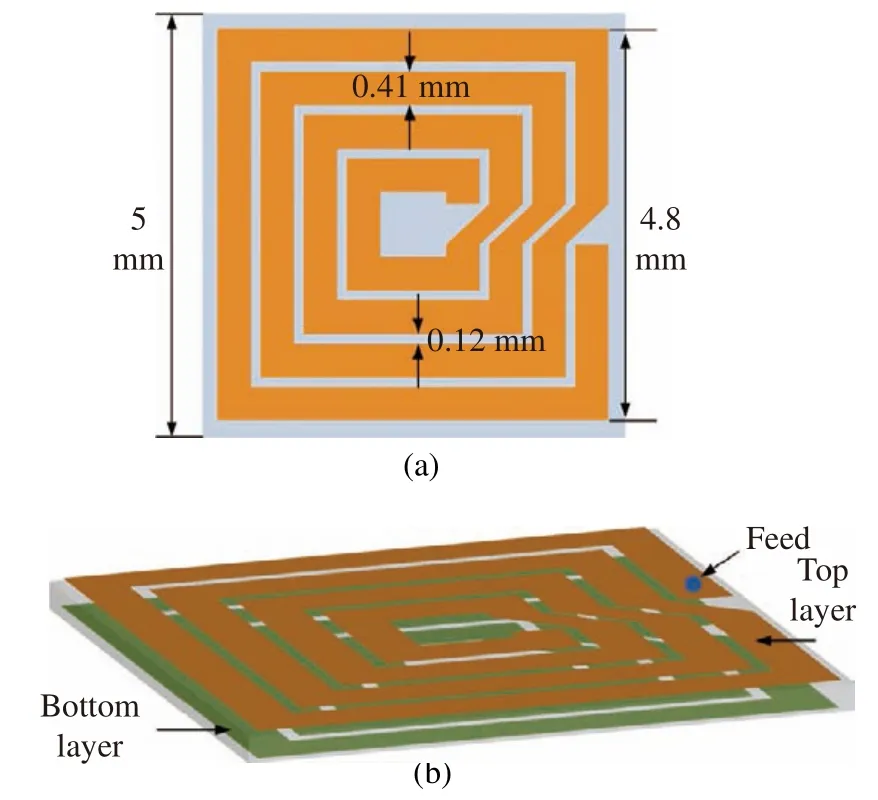
Fig.3 RX coil geometry:(a) top view;(b) the whole configuration

Tab.1 Different tissue properties
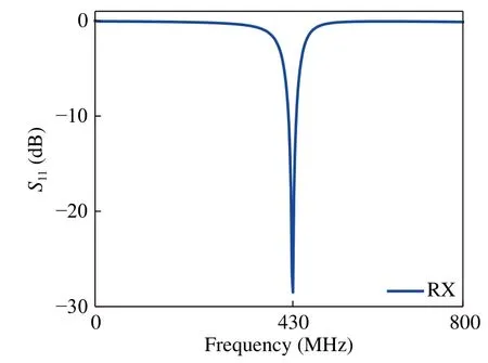
Fig.4 Reflection coefficient of the receiving coil
3 Results and Discussion
3.1 Simulation Setup
The WPT system includes the transmitting coil,receiving coil,and human tissue layer in biological applications,as shown in Fig.5.The distance between the external transmitting coil TX and the skin surface is labeled d1,and the distance between the skin surface and the implanted receiving coil RX is labeled d2.The transfer efficiency η of the WPT system can be calculated using the S21results,that is η=|S21|2.Accordingly,the S21results are chosen as the performance indicator to evaluate the system transfer efficiency in the following work.
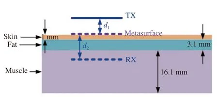
Fig.5 Overall structures of the design and three-tissue-layer model
3.2 The Effects of d1 on S21
First,assuming d2=0.5 mm,2.5 mm,and 12 mm,the RX coil is implanted into the middle of the skin layer,middle of the fat layer,and middle of the muscle layer,respectively.d1is changed from 10 mm to 60 mm at 10 mm per step.The variations in S21with a distance of d1are depicted in Fig.6,which shows that S21quickly decreases with increasing distance d1between the external transmitting coil TX and the skin surface.When the receiving coil RX is implanted in the middle of the skin layer,that is d2=0.5 mm,the transfer efficiency ranges from–46 dB to–119 dB.When the receiving coil RX is implanted in the fat layer,that is d2=2.5 mm,the transfer efficiency ranges from–26 dB to–122 dB.When the receiving coil RX is implanted in the muscle layer,that is d2=12 mm,the transfer efficiency ranges from–63 dB to –136 dB.
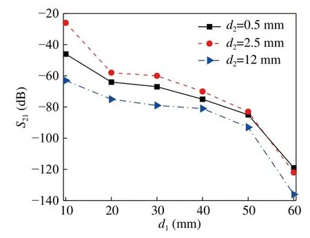
Fig.6 Variations of the S21 with the distance of d1
3.3 The Effects of d2 on S21
Then,assuming d1is 10 mm,d2is changed from the skin layer to the muscle layer with different per step.Because of the different material properties of the three tissues,the variations in efficiency are different,as shown in Fig.7.It can be seen that the S21quickly decreases with the increase of d2in the skin and muscle layers,whereas the S21quickly increases with the increase of d2in the fat layer.The potential causes are the differences in dielectric properties,including permittivity and conductivity,for the different tissues.The values of permittivity and conductivity of the skin layer and muscle layer are higher than those of the fat layer,which may cause the S21variations of the skin and muscle layer to be opposite to those of the fat layer.
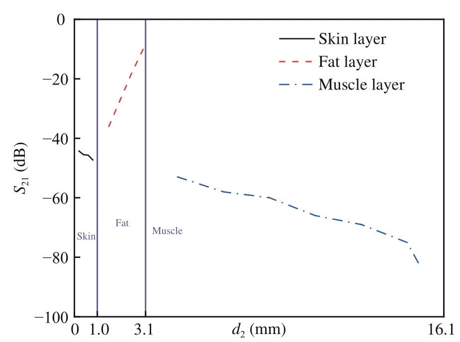
Fig.7 Variations of the S21 with the distance of d2
The relationship between the transfer efficiency η and d2can be expressed as the following equations.
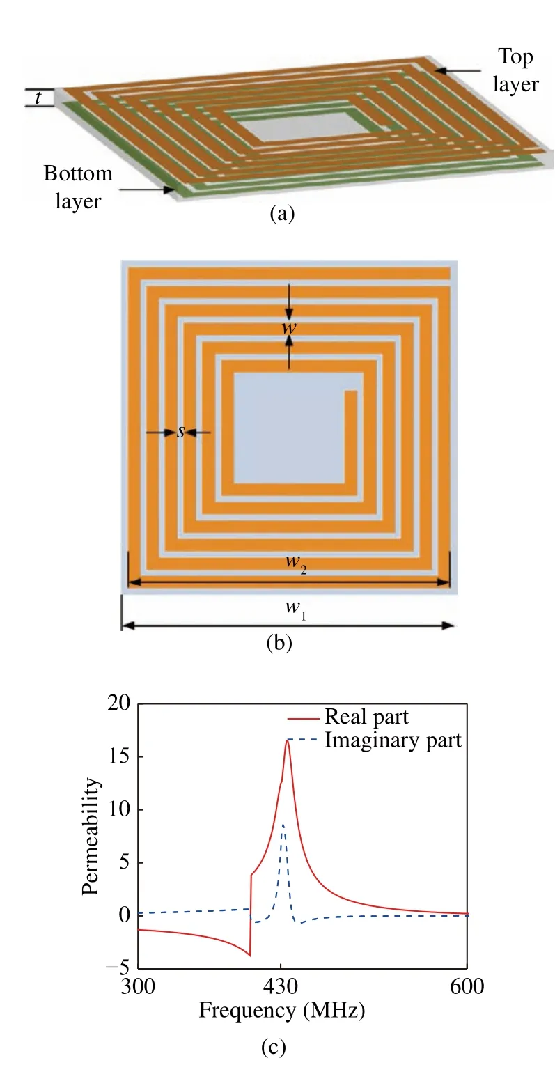
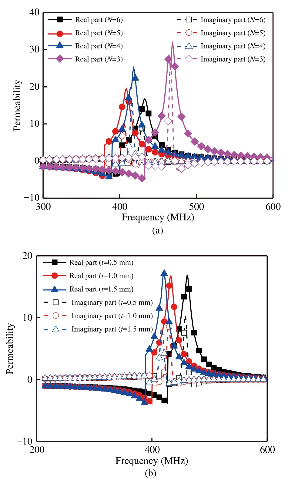
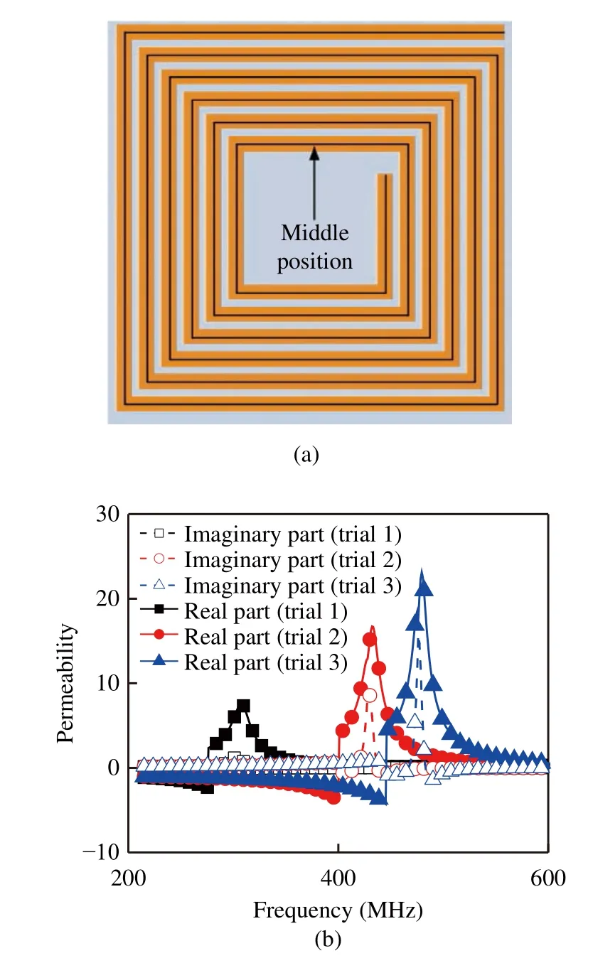
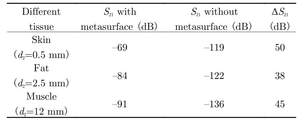
When the implanted receiving coil RX is located in the skin layer,that is,0 When the implanted receiving coil RX is located in the fat layer,that is,1 mm When the implanted receiving coil RX is located in the fat layer,that is,4.1 mm It is generally known that the use of a metamaterial structure integrated into a WPT system will enhance the transfer efficiency.In this work,a metasurface is adopted in Fig.8 (a),which is composed of a dual-layer structure by etching both sides of a square spiral.The final metasurface structure used with dimensions of 8.4 mm ×8.4 mm × 1 mm by arraying 3 × 3 unit cells is fabricated on the FR4 substrate.The designed parameters are shown in Fig.8 (b),where w=0.43 mm,s=0.040 mm,w1=8.4 mm,w2=8.33 mm,and t=1 mm.The real and imaginary parts of the permeability are depicted in Fig.8 (c),where the number of spiral turns N=6.As shown in Fig.8 (c),the real part of permeability is approximately 16.52 at a frequency of 437 MHz,and the imaginary part of permeability is approximately 8.56 at a frequency of 432 MHz. Fig.8 Configuration of the metasurface:(a) the whole configuration;(b) top view ;(c) effective retrieved permeability The effects of the metasurface structure parameters on the effective permeability are determined.The real part and imaginary part of permeability would vary with the designed parameters.Fig.9 (a) depicts the effective permeability with N variation. The resonant frequency would decrease when N changes from 6 to 5,and then increase as N decreases from 5 to 3.As N changes from 6 to 3,the real parts of the permeability are 16.73,19.50,25.03,and 31.73 with resonance frequencies of 432 MHz,409 MHz,418 MHz,and 469 MHz,respectively.The imaginary parts of the permeability are 8.89,10.73,16.36,and 27.93 with resonance frequencies of 429 MHz,405 MHz,416 MHz,and 467 MHz,respectively. In addition,when the thickness t of the substrate increases from 0.5 mm to 1.5 mm per 0.5 mm,the resonant frequency decreases,as shown in Fig.9 (b).As t increases from 0.5 mm to 1.5 mm,the real parts of the permeability are 16.82,16.73,and 17.22 with resonance frequencies of 461 MHz,432 MHz,and 420 MHz,respectively.The imaginary parts of the permeability are 10.43,8.89,and 8.38 with resonance frequencies of 458 MHz,429 MHz,and 417 MHz,respectively. Fig.9 Effective permeability of metasurfaces with different structural parameters:(a) N variation ;(b) t variation To identify the effects of width w and gap s on the effective permeability,the middle positions with solid lines as shown in Fig.10 (a),are kept the same,and the width and gap are altered at the same time.The different cases with different widths and gaps are tabulated in Tab.2,responding to trial 1,trial 2,and trial 3.Tab.2 presents that when the width increases,the gap decreases.ww is the product of w and s,which represents the total effect of the width and gap on the permeability.Fig.10 (b) shows that as ww increases,both the permeability value and resonant frequency increase.The real parts of the permeability are 7.25,16.67,and 23.12 with resonance frequencies of 308 MHz,432 MHz,and 479 MHz,respectively.The imaginary parts of the permeability are 1.27,8.89,and 15.83 with resonance frequencies of 302 MHz,429 MHz,and 476 MHz,respectively. Fig.10 Effective permeability of metasurfaces with different structural parameters:(a) illustration; (b) results comparison Tab.2 Different trials with different parameters When the metasurface is integrated between the transmitting and receiving elements,the transfer efficiency will be improved.Tab.3 tabulates the S21result comparisons as a function of distance d2with and without the metasurface,corresponding to the skin,fat,and muscle layers.It can be clearly observed that the performance of the whole WPT system can be enhanced using the metasurface structure. Tab.3 Variation of WPT efficiency with the different tissues A comparison between the proposed WPT system and other designs in the literature is tabulated in Tab. 4. The related parameters are defined as follows:the transfer distance D of the WPT system,the ratio a of the transfer distance to the side or diameter of TX,and the ratio b of the transfer distance to the side or diameter of RX.c is the product of a and b,which represents the total effect of the transfer distance,TX size,and RX size on the transfer efficiency.The parameters a,b,and c are dimensionless quantities.Inspection of Tab.4,the variations of transfer coefficients dramatically increase with the increase of c ranging from 1.4 to 14.4.The properties of the proposed system have obvious advantages compared with the TX size,RX size,metasurface slab,and transfer distance,which exhibits the characteristics of small size and high efficiency for biomedical applications. Tab.4 Comparison of the proposed WPT system with other designs In this paper,an improved magnetic coupling resonant WPT system including a transmitting coil,receiving coil,and metasurface structure is proposed for biological device applications.Similar planar copper coil structures of TX and RX elements are utilized to constitute the fundamental WPT system.A metasurface element is integrated into the essential system to enhance transmission efficiency.The results indicate that an enhancement efficiency of 38–50 dB can be obtained by comparing the primary WPT system without the metasurface.Hence,the proposed whole WPT system can be a promising and competitive system for use in practical biological applications such as capsules,pacemakers,cochleas,and other brain-computer interface devices.


3.4 The Analysis of Metasurface

3.5 The Efficiency of Integrated Metasurfaces in WPT Systems

4 Conclusion
杂志排行
Journal of Beijing Institute of Technology的其它文章
- Comparative Study on Galvanic-Coupled Intrabody Channel Characteristic Measurement Methods
- A 2Mbps Human Body Communication Transceiver Based on Body Antenna Effect
- A Modeling Method of the IBC System Based on the Composite Fading Channel
- A Comparative Study of the Electrodes Gels’Electrical Properties in the Measurement Issues of Intrabody Communication
- A Novel Flexible Antenna at Very High Frequency Band for On-Body Applications
- The Wireless Power Transmission on the Wristto-Forehead Path Based on the Body Channel
