A 2Mbps Human Body Communication Transceiver Based on Body Antenna Effect
2022-03-03HuajieTangPengfeiAokunWangYuhangLiuJingzhenLiAbhishekKandwalZedongNie
Huajie Tang,Pengfei Ao,kun Wang,Yuhang Liu,Jingzhen Li,Abhishek Kandwal,Zedong Nie
Abstract:This paper presents a human body communication (HBC) transceiver for wireless body network applications.The transceiver employs on frequency shift keying (FSK) modulation and operates in 40 MHz–60 MHz which is the resonant frequency of the human body as an antenna.It achieves high performance and stability through establish passive microstrip line and via models and active device-models.The proposed transceiver is designed and fabricated by FR4 printed circuit board (PCB) process,the transceiver has the ability of configurable data rate up to 2 Mbps and it achieves–86 dBm receiving sensitivity at 2 Mbps data rate.Meanwhile,the transceiver output power dynamics range is 34 dB.Furthermore,with a visual interaction interface,the transceiver can be agility use in a variety of scenarios.Its measurements are verified on human body.The result shows that the transceiver has ability to send data from person to person by relying on human body antenna radiation.The transceiver shows great prospect in wireless body area networks(WBAN) for telemedicine and emergency communication.
Keywords:human body antenna;human body communication(HBC);transceiver;wireless body artworks(WAN);frequency shift keying (FSK) modulation;medical monitoring
1 Introduction
The Coronavirus disease 2019 (COVID-19) pandemic has become the most serious public health problem in the world [1].And thus,human society is facing some major challenges,one of them is medical monitoring such as diabetes [2],cardiology [3],cancer [4],etc.The wearable monitoring systems which can provide early detection is a important solution of medical monitoring.Research has shown that through a network connecting of sensors and actuators which attached on or implanted in the human body can achieved monitoring vital signals.Such network is called as wireless body area networks (WBAN) [5].There are two approaches to achieving the WBAN:the first approaches is the utilizing the human body itself as a transmission medium which named human body communication(HBC) and the other using wireless mediums such as industrial scientific medical (ISM) band which including bluetooth (BT) . Compare to wireless mediums,HBC can operate with good signal-to-noise ratio (SNR) performance in the low-frequency band with lower power and provide person-specific communication channel with broadband [6,7].Besides,the HBC has excellent data confidentiality for covert communication which is critical important in medical monitoring,because of electro-quasistatic localize the signals within the body [8].
Recent study shows that transceiver is important device in WBAN [5,6,9].There are two principles about HBC transceiver.The first principle of HBC transceivers is use electrodes which placed on or close to human body instead of antennas to couple signals to the human body such as capacitive coupling,galvanic coupling,and magnetic coupling [10−16].The other important principle about HBC transceiver is the human body which have high dielectric constant and large physical dimension can be equivalent as an antenna in some frequency regions [17−21].The focus of the current studies are mainly focused the coupling HBC transceivers [7,11,22].The coupling HBC transceiver have advantage in signal transmission stable and reliable,but he communication distance between the transmitter and the receiver is not exceeding 150 cm [14].Consequently,in WBAN,the coupling HBC transceivers used to collect physiological data in medical monitoring.The transceivers have no ability to share data collected by itself in long-range.For this reason,it cannot be used for telemedicine monitoring and emergency communication.In contrast,the human body antenna which utilize body antenna effect with resonance frequency at 40 MHz–60 MHz and its radiation efficiency reaching up to 70 % can be used in energy harvesting and long-distance wireless communication [17,18].Take advantage of this merit,in WABN,the transceivers take advantage of human body antenna effect not only have ability to perform communication between personal devices and internet,but have ability to achieve longrange data share in medical monitoring.
In previous papers,the transceiver of coupling principle has attracted many researchers.The human body antenna effect transceiver is rarely reported.In this paper,we design a HBC transceiver based on human body antenna effect.The transceiver can be used in remote health data communication and emergency communication.In section 2 of this paper,the characteristic of transceiver is summarized,the principle of design is analyzed and transceiver architecture is described.A circuit design of HBC transceiver with FSK modulation is presented in section 3.The performances of the transceiver are measured by experiment and its results are discussed in section 4.Finally,this paper is summarized in section 5.
2 Transceiver Architecture
A block diagram of the transceiver system is schematically outlined in Fig.1,the complete receiver is made up of deModulator,Rx_BPF,Rx_Mixer,Rx_LPF,LNA,SW,BPF and PLL;the complete transmitter is made up of Modulator,M_LPF,Tx_Mixer,LPF1,PA,PA_LPF,SW,BPF and PLL.The transceiver system have three functional units: 1) Microcontroller unit(MCU) with a man-machine interface use for the processing of data and information interactions,2) Modulator and demodulator are used to modulate digital signals to the FSK carrier signal and demodulate FSK carrier signal to digital signals,3) Radio frequency (RF) analog front end which includes power amplifier (PA),low noise amplifier (LNA),phase-locked loop (PLL),band-pass filter (BPF),low-pass filter (LPF) and switch(SW).The transceiver has the following five key features. Firstly,it working at human body antenna resonance frequency in 40 MHz–60 MHz,which can utilize human radiation power to reduce the antenna size.Secondly,time division duplex (TDD) is proposed to up-and-downlink data transmission.A frame structure which including synchronous sub-frame,media access control address (MAC) sub-frame,data sub-frame and cyclic redundancy check (CRC) sub-frame is designed to realize synchronization,inspection and data transfer. The MCU switch control strategy is decided by frame structure in order to achieve isolation of uplink and downlink in the TDD transceiver.Thirdly,FSK modulation with adjustable data rate up to 2Mbps are adopted because FSK is better than on-off keying (OOK)and quadrature amplitude modulation (QAM) in HBC channel [23]. Fourthly,compared with coupling transceiver whose balun and ground electrode are essential [23],the transceiver based on human body antenna effect employ innovative electrode feed with balun-less and groundelectrode-less.Finally,the transceiver has more practicality than the application specific integrated circuit (ASIC) transceiver based CMOS technology [24,25].
In the design of receiver system,the receiver sensitivity is an important indicator to verify the transceiver have ability to receive.The receiver sensitivity has been defined as a minimum signal received from antenna connector with block error rate (BLER) less than 0.1% [26].In theoretical,system sensitivity is given as [27] :

where –174dBm is the thermal noise power of 50 Ω input resistance,S/N is signal to noise ratio,B is channel bandwidth,Nsysis system noise figure.Obviously,S/N and B are rest with demodulator in Fig.1.Nsyscan be flexible designed in a receiver.By using (1),the positive correlation between sensitivity and Nsyscan be find out.
The noise factor of receiver system with ncascaded stages defines as[26,28,29]

where Fnand Gnare noise factor and power gain of the n-th cascaded,respectively;Fsysis the receiver noise factor. The relationship between noise figure and noise factor is shown as

It can be seen from (1)–(3),the LNA is key component in receiver. Intuitively,the greater the gain and the smaller the noise factor of LNA,then the lower the sensitivity.And thus,LNA is indispensable in the receiver in Fig.1.In receiver chain,a mixer is needed to convert the carrier frequency into the frequency that the demodulator can detect.In order to improve performance of the receiver,band-pass filter immediately next to the mixer is designed to filter the harmonic from mixer and suppress carrier leakage.
At lower frequency (below 3GHz),the Friis Equation is used to estimate distance related loss for an atmospheric medium [30].For HBC that apply to far-field wireless monitor,the medium are human body and atmospheric. The Friis Equation should be take the Humantenna effect and human loss into account.Consequently,the Friis Equation should be modified as

where Pris the power received;Ptis the power transmitted;Gteis the transmitter electrode gain;Greis the receiver electrode gain,Gthis the transmitter Humantenna gain;Grhis the receiver Humantenna gain;Lhis the human body loss;Lfsis the free space loss.Gthand Grhare depending on the human electromagnetic performance [17].Gteand Greare geometry-related by electrode.Lfsis decided by frequency and distance.Application of the equation (4),one can find that when Pris equivalent to sensitivity the Lfswill tend to the limit communication distance and the greater the power Pt,the farther the distance.So a PA is beneficial to the presented transmitter in Fig.1.The transmitter chain include a modulator,LPF,mixer,PA,SW and BPF.The LPF is used to filter harmonic and BPF is designed to suppress out-of-band spurious.
3 Circuit Design Techniquesm
3.1 BPF design
For the transmitter,there are two work patterns will produce unwanted signal:the power amplifier distortion lead to high-order harmonic and the mixer combined frequency interference.For the receiver,after the electrode connecting to the human body,there are many low frequency and high frequency interference noises.The low frequency noises consists of the environmental electrical equipment interference,the human body physiological electric noises and industry frequency noises. The high frequency noises are comprised of RF band interference,radio interference and high-order harmonic [31].So BPF is designed to remove the unwanted signals.Fig.2 is the BPF circuits,the network used in this design is shown detail below:C1 is DC-blocking capacitance,C3 and L1 are part of the band rejection filter with resonance frequency f1,C6 and L2 are part of the band rejection filter with resonance frequency f2,C7 is used to matching electrode with human body.By optimizing the resonant frequency f1and f2,a BPF can be come true.Microstrip line and via models were established to simulation the BPF with Advanced Design System (ADS).The S-parameters was measured by Agilent E5061A vector network analyzer(VNA).The simulation and measurement of reflection and transmission coefficients are shown in Fig.3 . The simulation results are in good agreement with the test results.The filter insertion loss (IL) 0.85 dB at 40 MHz and 1.03 dB at 60 MHz,so the in-band flatness is outstanding with 0.18 dB around 40 MHz–60 MHz.But more importantly,higher order harmonic suppression up to 40 dB such as the third harmonic suppression is 25 dB and fourth harmonic suppression is 35 dB.
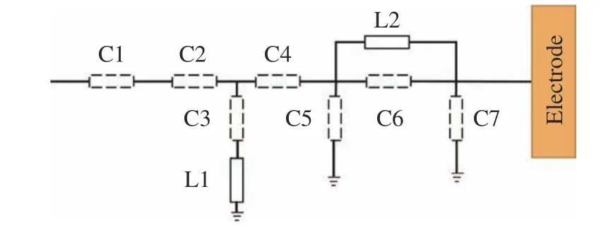
Fig.2 The design of BPF circuit
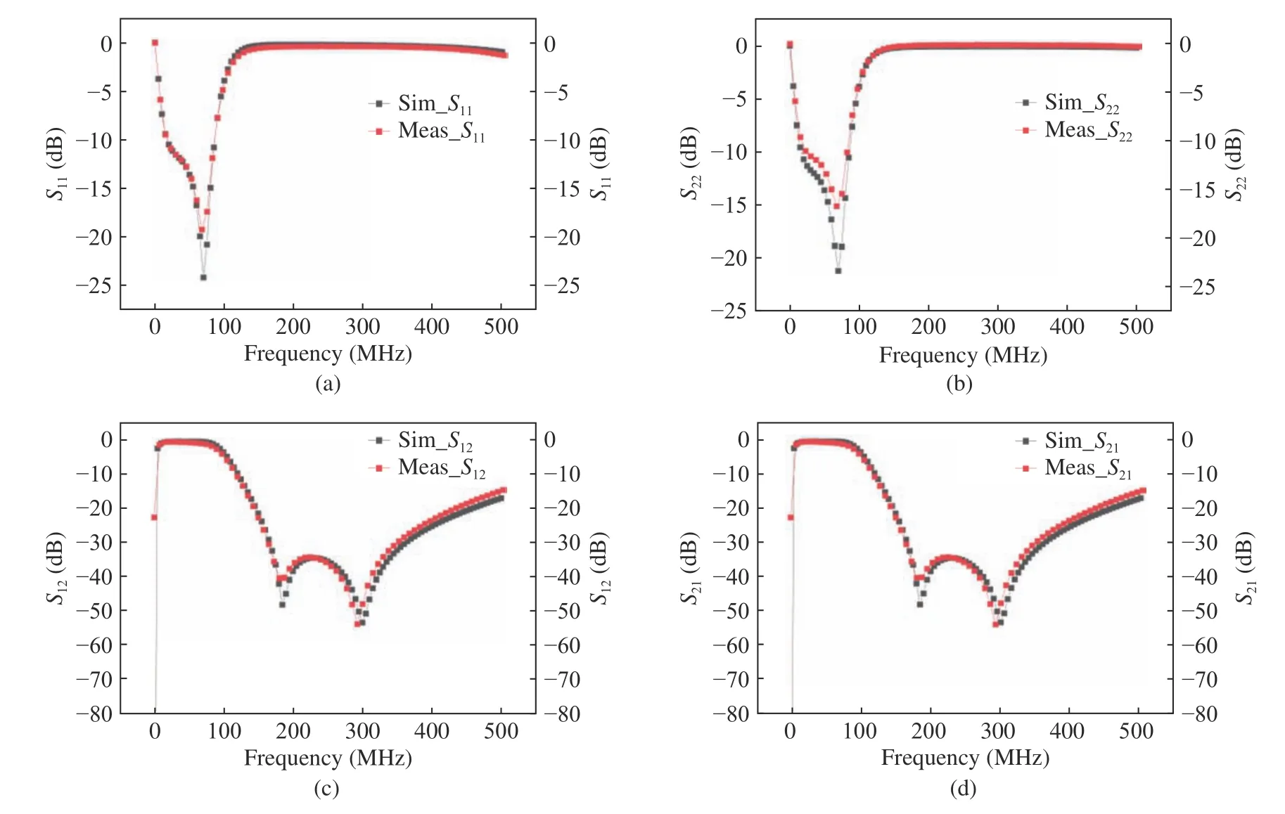
Fig.3 S-parameters of BPF from VNA measurements and ADS electrical simulation:(a) reflection coefficient S11;(b) reflection coefficient S22;(c) transmission coefficients S12;(d) transmission coefficients S21
3.2 Receiver Design
3.2.1 Low Noise Amplifier
The impedance matching is a critical role in LNA design [32].In order to ensure the accuracy of the simulation,a high-precision device models of LNA were established.Fig.4 shows that the LNA circuits compose of the input impedance and the output impedance network.Fig.5 shows that the LNA circuits S-parameters from measurements and ADS simulation.The S22is less than –10 dB means that the output impedance matches well at 40 MHz–60 MHz.The measure gain of LNA S21is consistent well with simulation.In Fig.5,the difference between measurements and simulation may be the IL of lumped element not take into account in the simulation.The stability of LNA,K-factor has been simulation to be greater than 1 with frequency under 110 MHz in Fig.6.This mean that the design is reasonable and it is unconditional stable at the operating frequency.In Fig.6 the noise figure of LNA is 1.27 after match which be used to assess the sensitivity.
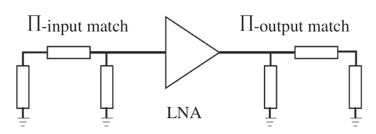
Fig.4 LNA input and output match circuits
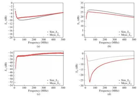
Fig.5 S-parameters of LNA from VNA measurements and ADS electrical simulation:(a) the input reflection coefficient of LNA S11;(b) the gain of LNA S21;(c) the reverse isolation of LNA S12;(d) the out reflection coefficient S22

Fig.6 Noise factor and stability factor of LNA:(a)noise figure;(b)noise factor and stability factor of LNA
By optimizing impedance matching,the results of receiver front end which include BPF,LNA,SW and RX_LPF S-parameters measurements and simulation are presented in Fig.7.The simulations value trends of S-parameters are consistent with the measured.The receiver front end gain in measure is 25.5 dB at 40 MHz and 24.5 dB at 60MHz,the simulation gain is 26 dB at 40 MHz and 25.5 dB at 60 MHz.The harmonic suppression of the receiver front end is–35dBc at 150 MHz,–63 dBc at 200 MHz.This means the receiver have the ability of rejecting harmonic interfere.The differences between the simulations and measured values of S-parameters may relate to the ignore of DE-embedding when testing and substrate material FR4 stability and impedance error caused by PCB processing.

Fig.7 S-parameters of receiver front end link from VNA measurements and ADS electrical simulation:(a) the input reflection coefficient S11;(b) the out reflection coefficient S22;(c) the gain S21;(d) the reverse isolation S12
3.2.2 Receiver BPF (Rx_BPF)
The nonlinear action of mixers propagates throughout signal chains generating undesired output such as second and third-order intermodulation [33].This is a critical problem faced in RF system design especially for receiver.For this reason,filters are often used to rejected image and carrier leakage [34].The elliptic filter with a LPF cascade connection is designed. T-type matching networks are used to optimize impedance matching performance among cascade and circuit is in Fig.8.The transmission response are shown in Fig.9.The S21is 46 dB at 50 MHz.This means that the high carrier leakage suppression is come true.

Fig.8 BPF circuit in receiver
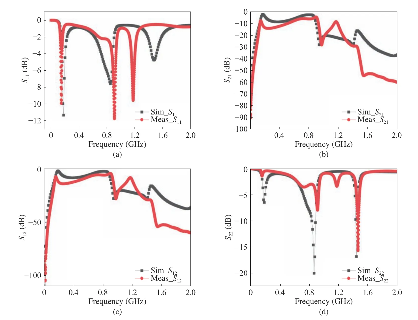
Fig.9 Measurement and simulation result of S-parameters with mixer output BPF in receiver:(a) reflection coefficient S11;(b) transmission coefficients S21;(c) transmission coefficients S12;(d) reflection coefficient S22
3.3 Transmitter
For PA,the load impedance matching will improve efficiency [35].Fig.10 shows the PA circuits.Output match employs RF choke (L2),series inductor (L3,L4),shunt capacitor (C2,C3,C4,C5,C6),DC block capacitor (C7).This match topology transforms 50 Ω system to suitable load impedance at characteristic frequency which in the transmitter is 40MHz–60 MHz.Multi-stage shunt C reserve for optimal performance,two stage L-C is designed for broadband match.Input match a high pass C-L filtering is designed and resistance is reserved for best noise figure.After output match optimal,the output match circuits simulation and measurement of transmission response are shown in Fig.11.The results are exact between simulation and measurement in DC–500 MHz.S22 is–17 dB can be found in Fig.11 . This mean that the output match circuits are greatly facilitated match to 50 Ω impedance system.Second and third harmonic suppression of center frequency are–7.7 dB at 100 MHz and–12 dB at 150 MHz,respectively,in Fig.11.The suppression is comparatively small because of the two stage L-C broadband match.Fig.12 shows the transmission response of PA which includes the matching of input and output circuits of PA,SW and BPF.The measurements is well agree with simulation.This suggestion that the circuits of transmitter completely correct.

Fig.10 PA impedance matching circuits
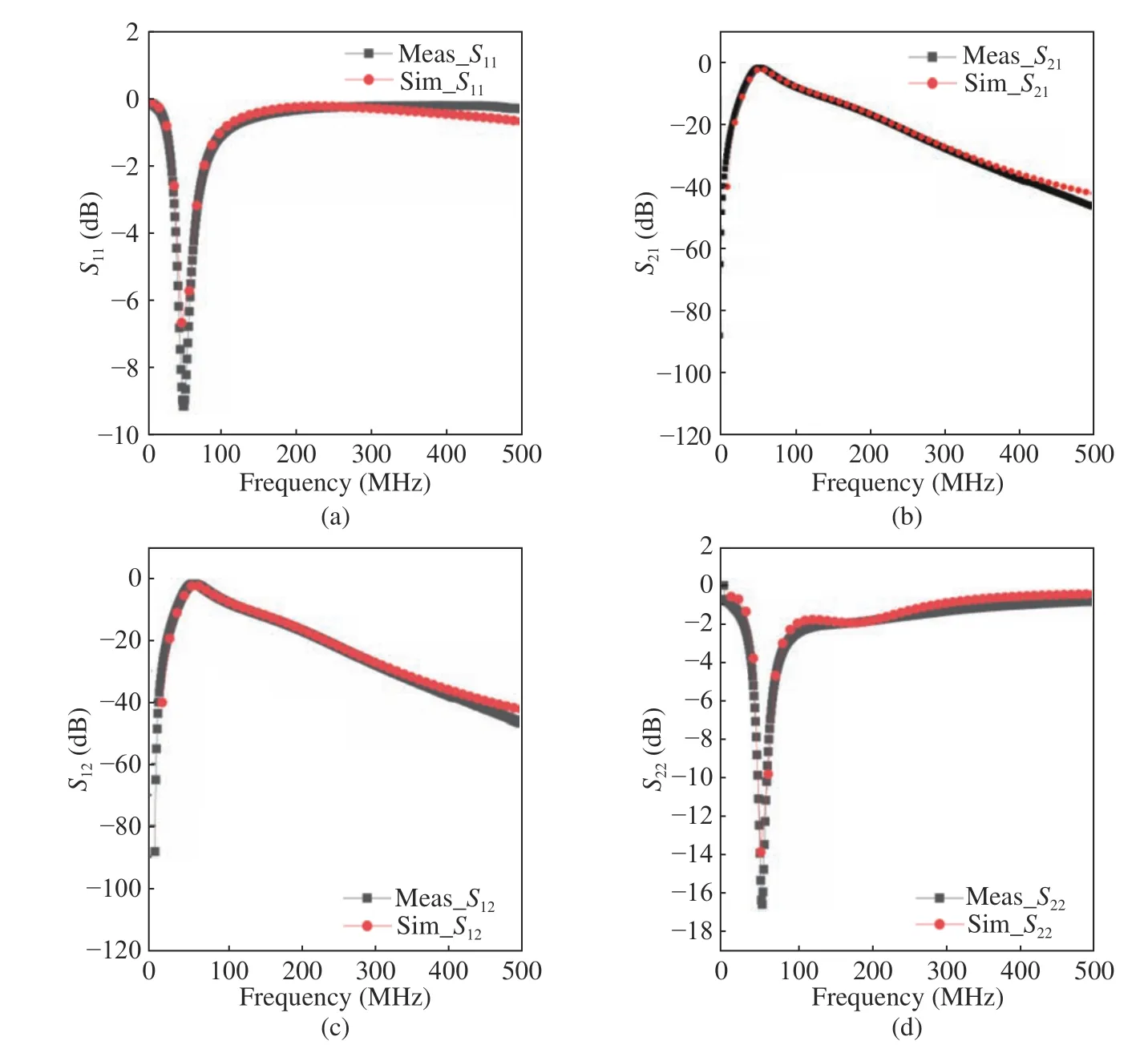
Fig.11 PA impedance matching circuits measurement and simulation result of S-parameters,where test port is near RF choke:(a) the input reflection coefficient of PA S11;(b) the gain of PA transmission coefficients S21;(c) transmission coefficients S12;(d) reflection coefficient S22
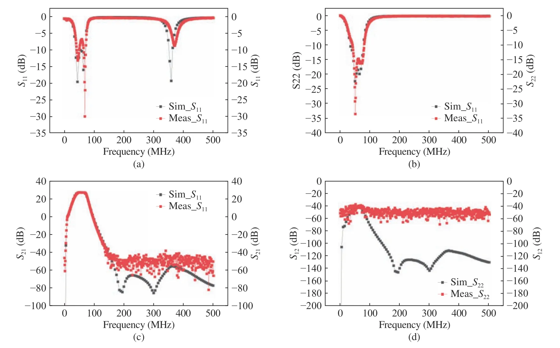
Fig.12 S-parameters of transmit link from VNA measurements and ADS electrical simulation,where include input and output circuits of PA,SW and BPF:(a) the input reflection coefficient of transmit link S11;(b) the output reflection coefficient of transmit link S22;(c) the gain of transmit link S21;(d) the reverse isolation of transmit link S12
4 Experimental Results
4.1 Transceiver
Oscilloscope was used to test data rate and FSK modulating signal.The physical map of transceiver PCB is shown in Fig.13 (a).The electric field distribution in human body with electrode coupling feed was analyzed by finite difference time domain (FDTD) method and finite element method (FEM) and the results show that most part of the electric field was concentrated around the arm[11].For this reason,the arm was selected as the electrode coupling feed position.The test setup is present in Fig.13 (b) :the right forearm volunteer A is wearing the electrode of the transceiver which used to send FSK signal and the left forearm volunteer B is wearing the electrode of the transceiver which used to receive FSK signal.The distance between volunteer A and volunteer B exceed 1m.The data is modulated and transferred though the human body A to the human body B.As future research,the different position and further distance will be considered.The test data is generated by the man-machine interface (touch screen) and handle by MCU on the transmitter with a data rate of 5 kbps and 2 Mbps.
Fig.13(c),(d),(e) shows the test result.As the data rate is equivalent to the data rate clock,5 KHz and 2 MHz data rate clock can be find in Fig.13 (c),(e),respectively.This means that the transceiver with 5 kpbs and 2 Mbps data rate is achieved.

Fig.13 The results of transceiver:(a) physical map of transceiver PCB ;(b) the test setup;(c) FSK time domain waveform with 5 kbps data rate,the period of data rate clock is 200 us,the frequency of data rate clock is 5 KHz;(d) FSK time domain waveform with 2 Mbps data rate;(e) FSK time domain waveform with 2 Mpbs data rate,the period of data rate clock is 500 ns,the frequency of data rate clock is 2 MHz
In addition,the data rate(DR) can be calculated as

where T is the time of data transmission,N is number of bits for the transmit data.When data rate is calculated the N is equal to 960 bits data which from MCU.From Fig.13 (d) the time T is 558 μs.Using formula (5),a data rate 1.72 Mbps can be calculated. There exist errors between data rate calculated and data rate clock,the reason is a protective gap about 100 μs is used for Tx and Rx switching.Taking 100 μs into account,by using formula (5),the data rate re-calculated is about 2.0 Mbps.
4.2 Receiver
The schematic of receiver sensitivity test is present in Fig.14.Transceiver A launch 22 dBm fixed power signal and through the attenuator transceiver B receipt the signal from transceiver A.Meanwhile,the computer calculates the receive BLER.Adjust the adjustable attenuator,the curve of BLER shows in Fig.15.From the curve receiver sensitivity is about –83 dBm at 2 Mbps.Theoretically,sensitivity can be calculated by using (1),when the Nsysis determined.Fig.16 is the theoretical Nsys,the sensitivity is calculated about–90dBm by using (1).The difference between the test and simulation may be RF coaxial cable loss not involved in test system.Besides,the NF simulation parameter is theoretical such as LNA gain is 31 dB in Fig.16(a).The real sensitivity is about –86 dBm by correcting cable loss 3 dB.The theoretical Nsysis 5.5 by correcting LNA parameter.So the sensitivity is about–87.8 dBm theoretical.The measured values and the theoretical values agree well.
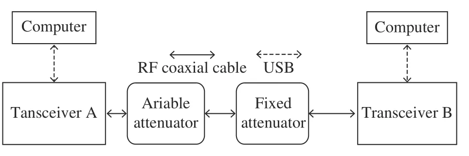
Fig.14 Block diagram of receiver sensitivity test
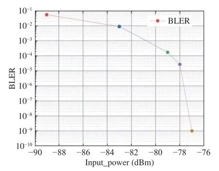
Fig.15 Measured curve of BLER with 2 Mbps data rate
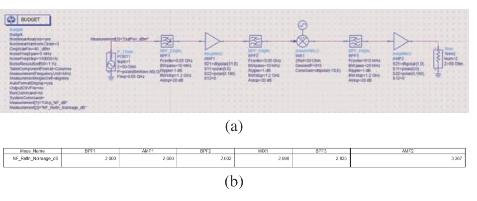
Fig.16 Receiver performance simulation:(a) the simulation model of receive chain;(b) the Nsys result of simulation
4.3 Transmitter
Spectrum analyzer is used to test transmitter power.Fig.17 (a)(b) shows the maximum power of the transmitter at different data rates of 100 kbps and 2 Mbps,respectively.The maximum power is 23 dBm when the transmitter working at 100 kbps data rate and 21 dBm when the transmitter working in 2 Mbps data rate.The deviation of FSK is 190.4 kHz/198.4 kHz when transmitter working in 100kbps and 504.7 kHz/495.2 kHz when transmitter working in 2 Mbps.The bandwidth of 40 MHz– 60 MHz is shown in Fig.18 tested under 5 kpbs data rate.The results indicate that the presented transmitter works well.Dynamic power range is about 34 dB with the transmitter and the result present in Fig.19.With the increase of digital to analog conversion(DAC) value the output power increases near linearly.It can be deduced that the power amplifier works in a linear state and it means that the design of transmitter is correct.
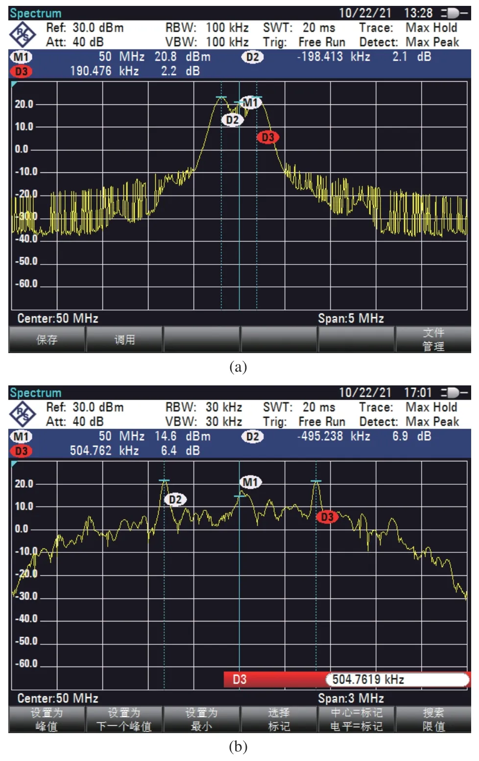
Fig.17 The transmitter power at 50 MHz with different data rate:(a) 100 kbps;(b) 2 Mbps
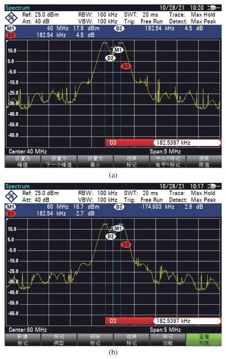
Fig.18 The transmitter bandwidth test result is 20 MHz:(a)40 MHz signal carrier with FSK;(b) 60 MHz signal carrier with FSK
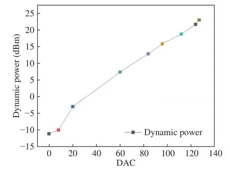
Fig.19 The output dynamic power curve of the transmitter
5 Conclusion
This paper proposes a transceiver with FSK modulation technique.A mixer,power amplifier,low-pass filter,switcher,and band pass filter are designed in the transmitter part.The receiver chain are comprised of band pass filter,mixer,low noise amplifier and switcher.The band pass filter which close to the switcher is used to the suppress the harmonics generated by the power amplifier when transmitter working and extract the useful carrier frequency from a broadband input noise frequency when receiver working.Low noise amplifier designed is used to improve the system NF for increasing sensitivity.The other band pass filter approached mixer is designed for carrier suppression.The proposed HBC transceiver is manufactured by a sheet of a dielectric FR4 PCB board.Thanks to these features,the transceiver based on human body antenna effect was implemented data communication.In order to using human body as a antenna,the test setup signal feed is located at the arm of human body which based on the finite element simulation results.The test results shows that the service frequency of the transceiver is 40 MHz–60 MHz which consistent with the resonant frequency of the human body as an antenna.The data rate of this transceiver is configurable from 5 kbps up to 2 Mbps to improve the agility of transceiver,which means the transceiver have the ability to adapt to various application environments.The receiving sensitivity is about–86 dBm at 2 Mbps data rate.The transceiver shows great prospect in WBAN and urgent communication such as remote medical monitoring at COVID-19 pandemic.
杂志排行
Journal of Beijing Institute of Technology的其它文章
- Comparative Study on Galvanic-Coupled Intrabody Channel Characteristic Measurement Methods
- Design of Wireless Power Transfer with High Efficiency for Biomedical Implants
- A Modeling Method of the IBC System Based on the Composite Fading Channel
- A Comparative Study of the Electrodes Gels’Electrical Properties in the Measurement Issues of Intrabody Communication
- A Novel Flexible Antenna at Very High Frequency Band for On-Body Applications
- The Wireless Power Transmission on the Wristto-Forehead Path Based on the Body Channel
