Barium Ferrite Millimeter Wave Absorbing Material Based on Multiple Landé Factors and Low Anisotropic Field
2022-02-28LIUJianLVShuangCHENSiyiWANGYuechuWANGXiaolongWANGMinWANGZongrongDUPiyiLILei
LIU Jian, LV Shuang, CHEN Siyi, WANG Yuechu, WANG Xiaolong, WANG Min, WANG Zongrong, DU Piyi, LI Lei
(State Key Lab of Silicon Materials, School of Materials Science and Engineering, Zhejiang University, Hangzhou 310027, China)
【Abstract】 Both V5+ substituted and V5+-Ni2+ co-substituted barium ferrites have been prepared by sol-gel technology. The powder samples have been characterized by SEM, XRD, and XPS. The electromagnetic performance has been measured by the vector network analyzer. Compared with V5+ substituted system, the co-substituted ferrites show better microwave absorbing performance by decreasing the magnetic anisotropic field and introducing three different Landé factors(g). When the matching thickness of V5+-Ni2+ co-substituted barium ferrites is about 2 mm, the maximum absorbing bandwidth can reach about 8 GHz and the reflection loss(RL) is lower than -60 dB. Moreover, the co-substituted barium ferrites can achieve wider tunable frequency range, which makes it a promising absorbing material.
【Key words】 V5+-Ni2+ co-substituting; Barium ferrite; Sol-gel; Magnetic anisotropic field; Microwave absorbing material
1 Introduction
With the fast development of modern electronic devices and telecommunication systems in various applications, including radar technology of military, signal transmission and etc., electromagnetic (EM) pollution has also become a serious issue to be concerned, which will cause damage to the environ-ment and health of human being[1-6]. Besides, millimeter waves in the frequency range from 30 to 300 GHz, especially atmospheric windows of 35, 94, 140 and 220 GHz, are important for the radar detection due to low atte-nuation of microwave during transmission in the air[3-5]. In this case, high performance EM inter-ference or the absorbing materials are both highly required in both civilian area and military tech-nology, including human health, microwave darkrooms, stealth materials etc[2,7-11]. If a high performance microwave absorbing material is deve-loped, which will absorb millimeter wave near atmospheric windows, it can be applied to the military field[12].
Theoretically, the perfect absorbing material should be with broad bandwidth (the frequency range where the EM waves can be strongly absorbed) and strong absorption ability (the frequency intensity where the EM waves can be strongly absorbed) of the EM waves. According to the transmission theory, the EM absorbing performance quantified by parameter reflection loss (RL), which is determined by many factors, including impedance match, attenuation constant and so on. Firstly, the impedance of the absorbing materials should approach that of the air to allow EM waves to enter the materials as many as possible, namely the better impedance match should be assured. Secondly, attenuation means a measure of the rate of attenuation per unit length, which is the rate of flux-density (or power) reduction as energy (visual, electromagnetic, acoustic) propagates from its source.
Actually, attenuation constant is positively correlated with both magnetic loss and dielectric loss, which are the ratio of the imaginary part of the permeability and the permittivity to the real part of the respective real part. If a material possesses high dielectric and magnetic loss in nature around some specific frequency, it will be a promising EM absorbing materials for that frequency. M-type barium ferrite BaFe12O19(BFO) has been proposed to be one of the most potential microwave absorbers based on its high magnetic loss[2,4]. It is well known that the magnetic loss of barium ferrite is mainly attributed to its natural resonance, which make it strongly absorb the microwave near 45 GHz[7,13-14]. Fortunately, it has been proved that this frequency can be shifted to a lower frequency near 35 GHz, one of the atmospheric windows mentioned above[14-15]. However, there are two problems still need to be addressed, the RL is not strong enough in the specific frequency of 35 GHz and the bandwidth of the absorbing frequency is also not wide enough compared with the requirements of real application, which should be generally less than -50 dB and wider than 5 GHz, respectively[2,15-17]. In this case, to further enhanceRLand broaden bandwidth of BFO is highly required to achieve better performance.
Herein, the magnetic and dielectric loss should be increased near the specific frequency of 35 GHz of the BFO to enhance the attenuation of the absorbing materials and achieve the impedance match simul-taneously. On one hand, shifting the natural resonance frequency from 45 GHz to 35 GHz is an efficient way to increase the magnetic loss. The equationfn=(γ/2π)Ha=1.4gHa, gives the relation between the natural resonance frequencyfnand Landé factor(g), which is the ratio of the total effective magnetic moment of an atom to its total angular momentum, as well as anisotropic field (Ha), andfnthe peak value of pure BFO is near 45 GHz as mentioned above[2,14,16]. The enhancing of magnetic loss could be achieved by increasinggandHa. In a word, iffnshifts to the frequency near 35 GHz, the magnetic loss will be obvious in that specific frequency. As is reported, the tetravalent ions such as Ti4+and Zr4+are substituted into the barium ferrite to substitute the Fe3+[17-18]. In reality, as the guest ions with more than 3 positive charges substitute Fe3+, to keep charge balance, Fe3+is about to convert into Fe2+. Then the exchange coup-ling between Fe2+and Fe3+ions in the ferrites will generate more different Landé factors[7,16,19-21]. As a result, three magnetic resonance peaks and twoRLpeaks will be generated, which demonstrates that substituting Fe3+by other ions with more than 3 positive charges is an effective and simple way to gain excellent absorbing materials with broad bandwidth.
Other than Landé factors above, the microwave absorbing performance of BFO is also depending on the anisotropic field (Ha). The weaker the aniso-tropic field is, the lower the frequency of the peak of the natural resonance is. It is known that the anisotropic field (Ha) of BaFe12O19is attributed to Fe3+, which will be weakened if Fe3+is replaced by other non-magnetic or ions with weak magne-tism[9,13-14]. As analyzed above, if the guest ions possess more than 3 positive charges, Fe2+is supposed to be produced in barium ferrite. While the concentration of Fe2+in barium ferrite is limited because Fe2+is most likely to occupy the 2a site and there is only one in BaFe12O19[17,22]. This will restrict the amount of Fe3+being replaced. In this case, the shift to a lower frequency of magnetic resonance peaks will also be limited to some extent. Obviously, if both broad bandwidth and wide adjustable frequ-ency range can be obtained in one material simultan-eously, high performance microwave absorbing materials can be achieved.
Herein, V5+was firstly used to substitute the Fe3+in BFO, due to its non-magnetism and the similar radius to that of Fe3+. However, through the experiment of preparing the V5+substituted barium ferrite (BaFe12-yVyO19), the magnetic resonance peaks have not been shifted to the frequency lower than 40 GHz even for high substituting level withyof 0.5 and an impurity phase of Ba3(VO4)2appear in BFO, which has been reported to be one of the main phases of the material because of the serious lattice distortion[23]. Obviously, only one kind of substituting ion cannot solve the problem. Herein, we propose V5+-Ni2+ions co-substituted barium ferrites BaFe12-2xVxNixO19(x=0-0.8) to figure out the problem of the difficulty of the substitution of V5+for Fe3+, considering that radius of Ni2+and V5+is bigger and smaller than that of Fe3+respectively, which will alleviate the lattice distortion. And with the increase ofx, the magnetic resonance peaks move to 33 GHz until thex=0.6. Consequently, a thin matching thickness of 2.5 mm and a broad bandwidth of about 7.9 GHz can be obtained around the millimeter wavelength frequency of -33 GHz and the RL can reach -60 dB. Compared with the Zr-Ni co-substituted barium ferrite with 6.9 GHz bandwidth and -53.9 dB RL and Ti substituted barium ferrite with 11 GHz and -45 dB RL, the BaFe12-2xVxNixO19(BFVNO) has its prominent advantage[14,35].
2 Experiments
The V5+-Ni2+co-substituted barium ferrite powders (BaFe12-2xVxNixO19) were prepared by a sol-gel process. Barium nitrate (Ba(NO3)2, am-monium metavanadate (NH3VO3), nickel nitrate (Ni(NO3)2·6H2O), ferric nitrate (Fe(NO3)3·9H2O), and the appropriate amount of citric acid ammonia were raw materials. Firstly, Ni(NO3)2·6H2O, which were dissolved into deionized water to obtain a clear solutions. Ammonia was added gradually to adjust the pH values of the solution to 7.0. Then the solution was heated using the water bath at 80 ℃ with stirring till it became the sol precursor. Then the sol precursor was dried in an oven at 120 ℃ and further heated 450 ℃ for 2 h to ensure the sufficient decomposition of citric acid. Finally, the BFVNO powders were obtained by sintering at 1300 ℃ for 3 h. The V5+substituted barium ferrite BaFe12-yVyO9powders were prepared by the same way, just without nickel nitrate (Ni(NO3)2·6H2O) as the dopant of Ni2+.
In this study, the phase structure and morph-ology of the BFVO and BFVNO powders were respectively analyzed by XRD (XRD-6000, Cu Kα radiation) and SEM (Field Emission Scanning Electron Microscope, S-4800). The valances of Fe and O were analyzed by XPS (ESCALAB 250Xi). Hysteresis loops were measured by magnetic measurement system (Quantum Design, -9T-9T). The material was mixed with paraffin in a mass ratio of 4∶1 and heated about 80 ℃ for 30 min. Then the mixtures were filled into rectangular copper molds with rectangular openings for the mea-surement of EM parameters over the frequency range of 26.5-40 GHz (R-band) by an Agilent vector network analyzer (E8363C PNA). The RL was calculated by the trans-mission line theory.
3 Results and discussion
According to Fig.S1, Fig.S2, and Fig.S3, the conclusion is that the V5+can’t be substituted into the barium ferrite because of the lattice distortion and the formation of Ba3(VO4)2phase[23]. As a result, the natural resonance peak does not appear in the frequency of 26.5-40 GHz. In other words, theRLof the BFVO is not strong enough to absorb the EM waves. The lattice distortion resulted from the difference of the radius between Fe3+and V5+should be reduced. Hence, other ions larger than Fe3+should be brought in to release the distortion[9].
Fig.1 illustrates the SEM images of BFVNO powders with different V5+and Ni2+stoichiometry ratios ofx, ranging from 0 to 0.8. In all samples with different substituting level, only typical hexagonal plate-like particles can be observed, and the size of the particles increases along with the increase of the substituting amount because of the lattice distortion, which reduces the activation energy of the surface diffusion[15].

Fig. 1 SEM images of BFVNO
The phase content analyzed by XRD diffraction patterns of different samples is shown in Fig. 2. It can be seen that there is only a M-type barium ferrite phase whenxis below 0.3. And the phase, such asα-Fe2O3,γ-Fe2O3, appear in the barium ferrite with increasing of substituting levelx. The lattice parametersaandc, as well as cell volume of barium ferrites, are shown in Table 1. It is found thata,cand cell volume of barium ferrites firstly monotonously increase and then decrease with the increase ofx.
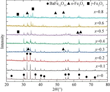
Fig. 2 XRD patterns of co-substituted BFVNO(x=0 -0.8)
It can be easily found that, in Table 1, the whole trend of the lattice of the barium ferrite is decrease. The ionic radiuses of V5+, Ni2+, Fe3+, Ba2+ions are 0.54, 0.69, 0.64, and 1.49 Å, respectively. As is known, V5+and Ni2+ions can substitute for Fe3+ions in barium ferrites because the radius difference between V5+, Ni2+ions, and Ba2+ions is so huge[24-25]. As a consequence, the lattice parameters and the cell will decrease due to the substitution of V5+, Ni2+ions because the radius of V5+is much smaller than those of Ni2+and Fe3+ions in barium ferrite, coinciding with the experimental results in Table 1. It proves that the V5+and Ni2+ions substitute for Fe3+ions in the barium ferrites.
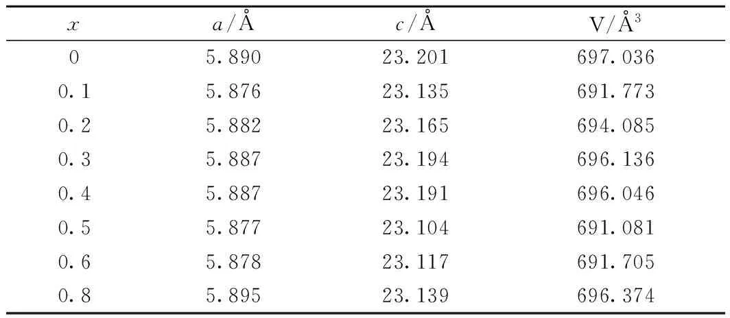
Table 1 Lattice constants (a and c) and cell volume of the BFVNO(x=0-0.8)
The XPS spectra for the Fe 2p and O 1s of BFVNO powders are shown in Fig.3 and Fig.4, respectively. The C 1s peak at 284.5 eV is used for energy correction. In Fig.3, Fe 2p1/2and Fe 2p3/2peaks have been resolved into two peaks distinctly in all samples.
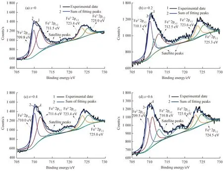
Fig. 3 Fe 2p XPS spectra of the BFVNO (x=0-0.6)
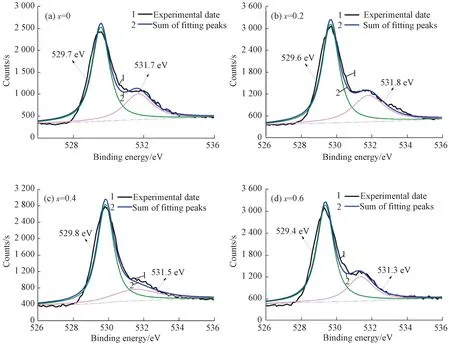
Fig. 4 O 1s XPS spectra of the BFVNO (x=0-0.6)
The peaks at about 711.8 eV and about 725.0 eV belong to Fe3+. The peaks at about 710.1 eV and 723.5 eV illustrate the existence of Fe2+. Besides, O 1s can also be resolved into two peaks at about 529.7 eV and about 531.7 eV. The one at about 529.7 eV is attributed to lattice oxygen ions O2-, whereas the other one at about 531.7 eV most likely to be the oxygen vacancies[2,24]. The concentration of Fe2+ions in all types of iron and oxygen vacancies calculated by peak areas is displayed in Table 2. It illustrates that the substituting contents of the V5+and Ni2+tox=0.2 will increase the concentrations of Fe2+and oxygen vacancies. What’s more, the concentration of Fe2+is almost unchanged with the increasing of the substituting contents, but the concentration of the oxygen vacancies increases firstly and then decreases whenx=0.2 to 0.4 and at last increases tillx=0.6-0.8.
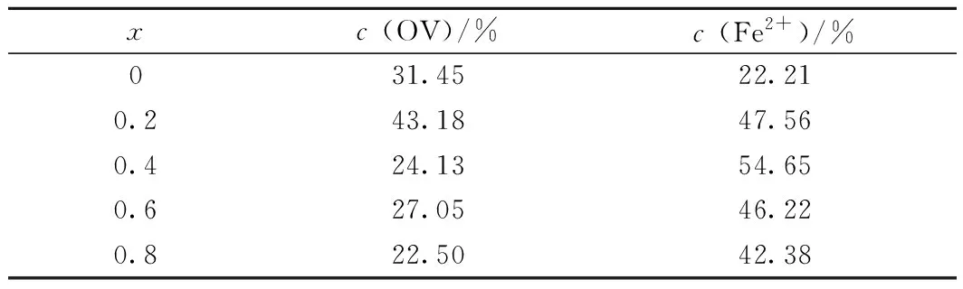
Table 2 Concentration of oxygen vacancy (OV) and Fe2+ in BFVNO (x=0-0.6)
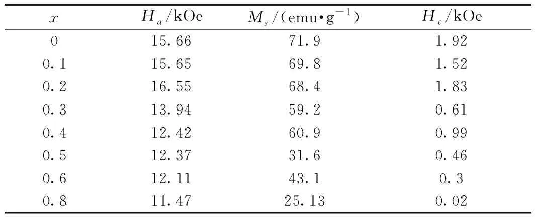
Table 3 Anisotropic field (Ha), saturation magnetization (Ms) and coercive field (Hc) of the BFVNO (x=0-0.8)
Fig.5 illustrates the magnetic hysteresis loops of the BFVNO powder sintered at 1300 ℃ for 3 h. It can be known that all the samples are approaching saturation with the applied field up to 30 kOe. The saturation magnetization (Ms), anisotropic field (Ha) and coercive field (Hc) of all the samples from hysteresis loops are summarized in table 3, in whichMsandHaare gained by the law of approach to saturation (LAS)[17,26-28]. It is seen thatHaof BFVNO decreases slightly from 15.66 kOe to 11.47 kOe with increasingxfrom 0 to 0.8.Hcalso decreases from 1.92 to 0.02. The overall tendency ofMsis decrease except forx=0.4 and 0.6.Msis influenced by the site of Fe3+in BFVNO substituted by V5+and Ni2+. As we know, the Fe3+in the 2a, 2b and 12k sites spin up and on the contrary Fe3+in the 4f1and 4f2spin down[9]. The saturation magne-tization in barium ferrite is contributed by the spin-up magnetic dipoles after counteracting the spin-down magnetic dipoles. That is, if the Fe3+ions at the 2a, 2b and 12k positions are replaced by V5+and Ni2+, the value of Ms will decrease. Conversely, if Fe3 +ions at positions 4f1and 4f2are replaced, the value ofMswill increase. Actually, the V5+and Ni2+ions might substitute with the Fe3+ions at both spin-up and spin-down sites in barium ferrite.
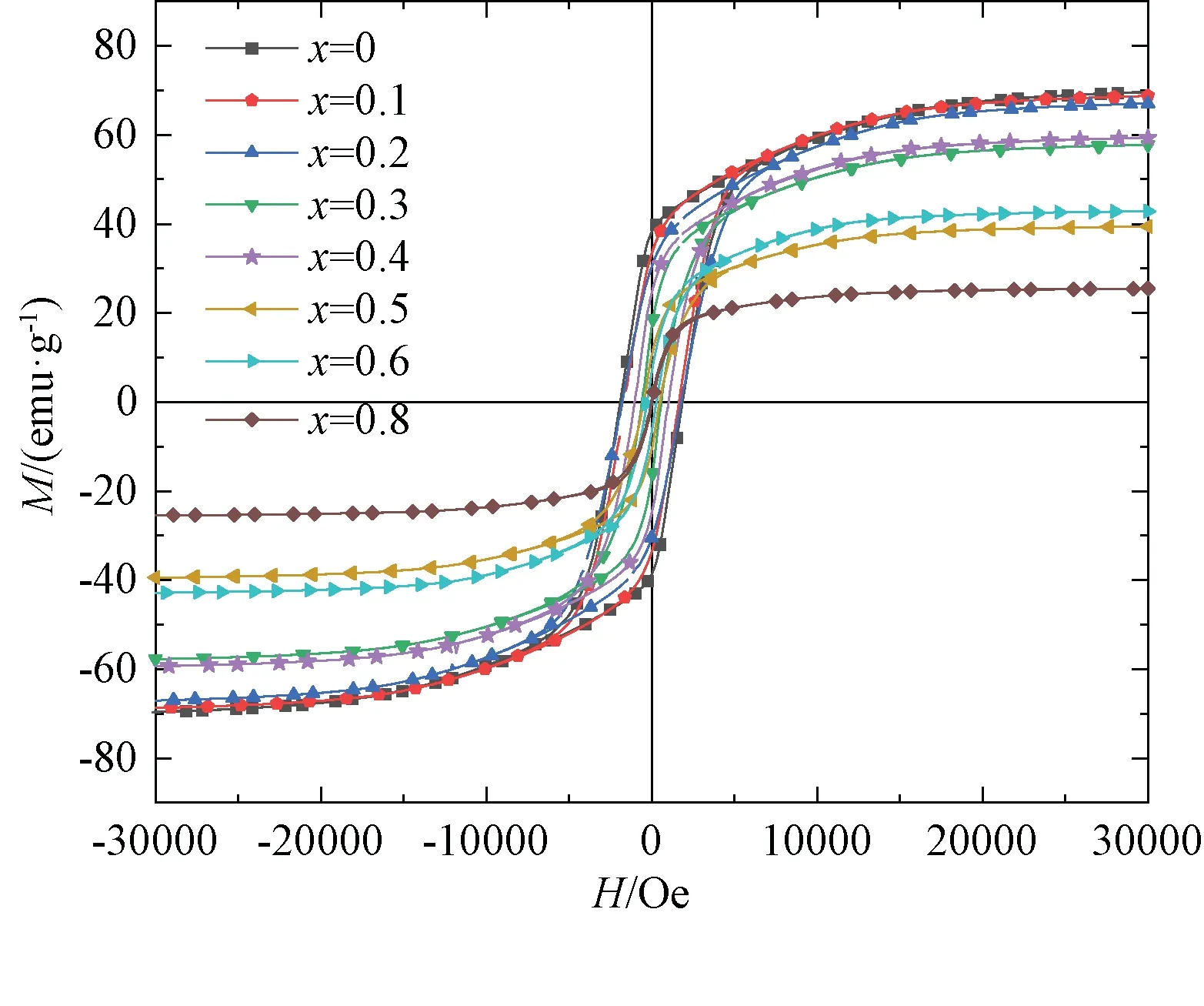
Fig. 5 Magnetic hysteresis loop of BFVNO(x=0-0.8)
In fact, the decreasedHaof BFVNO, with the increase of the substituting content of V5+, is ascribed to the substitution of non-magnetic V5+ions for the magnetic Fe3+ions[15,26]. And the Fe3+ions at 2b site contribute the mostHaof barium ferrite compared with the Fe3+ions at other sites[22]. Hence, it will be more efficient to reduceHaof the barium ferrite by V5+and Ni2+ions substituting for the Fe3+ions at the 2b site. As a result,Hadecreases slightly withxincreasing from 0 to 0.1, for V5+ions mainly substituting for Fe3+ions at the 4f1site. And it decreases dramatically fromx=0.1 to 0.8 due to V5+and Ni2+ions preferring to occupy Fe3+ions at the 2b site in the ferrites. In addition,Hcis mainly controlled byHaas well as grain size, reducing with decreasingHaor increasing with grain size and vice versa.
Fig.6 shows theε′,ε″,μ′ andμ″ of the BFVNO over the frequency range 26.5-40 GHz.ε′ of the ferrite increases has a whole trend of increase except for theε′ whenxis larger than 0.4 because of the impurity with the increasing ofx, andε″ possess completely the same trend asε′. What’s more, bothε′ andε″ are observed to decrease slowly with increasing frequency. Natural resonance peaks appear inμ″ for all the samples except the one without substituting over 26.5-40 GHz. The barium ferrite without substituting seems to show the peak at the frequency above 40 GHz. All the peaks in the ferrites shift simultaneously from high to low frequency with enhancing substituting amount of V5+and Ni2+ions.
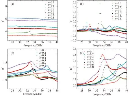
Fig. 6 ε′, ε′, μ′ and μ″ values of BFVNO (x=0.1-0.8) sintered at 1300 ℃ for 3 h
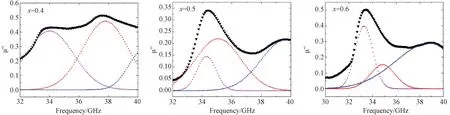
Fig. 7 Resolved natural resonance peaks of BFVNO (x=0.4-0.6)

Fig. 8 Schematic of BFVNO powders EM waves absorption mechanism: (a) and (b) the interaction between the EM waves and the BFVNO powders absorbers based on the model of the metal backplane; (c) the schematic of the BFVNO unit cell; (d) the mechanism of the natural resonance result from the resonance between direction of magnetic crystal anisotropy field and the saturation of magnetization and the image part of the permeability of the BFVNO(x=0.6) sintered at 1300 ℃ for 3 h
It’s well known that the magnetic loss of barium ferrite is mainly attributed to its natural resonance when the frequency increases to dozens of GHz[27]. Besides, it is reported that ferromagnetic resonance measurements (FMR) gave resonant peaks at the expected frequencies for pure phase materials at 45 GHz for barium ferrite, higher than the frequency of measure range. So the resonance peak is not present in the sample without substituting over 26.5-40 GHz. The ferromagnetic resonant frequency of barium ferrite with uniaxial anisotropy is:
fn=(γ/2π)Ha=1.4gHa
(1)
whereγis the gyromagnetic ratio andgis the Landé factor[17,26,29]. As shown in Table 3, according to the Eq.(1) and the reducedHaof the ferrites with co-substituting V5+and Ni2+, the resonance frequency will decrease as the content of the V5+and Ni2ions increased. As is seen, the amount of Fe2+ions increases with the increase of the co-substituting amount of V5+-Ni2+, which is supposed to be asc-ribed to exchange coupling between Fe3+and Fe2+in BFVNO[14,30].
Thegfactors for Fe3+and Fe2+ions are 2.0 and 3.54, respectively, and the exchange coupling between Fe3+and Fe2+contributesgfactors 2.0-3.54 of which the actual values depend on the amounts of the magnetic ions involved in coupling[2,20]. In Fig 7, based on Eq. (1), through resolving the natural resonance peaks of the BFVNO, thegfactors are calculated to be 1.95, 2.09, and 2.30 for the sample withx=0.4, 1.98, 2.03, 2.28 for the sample withx=0.5, and 1.97, 2.06, and 2.29 for the sample withx=0.6, respectively. Hence, the purple peak at the lowest frequency with minimumgof 2.0 is ascribed to Fe3+ions, and the red and blue peaks at higher frequencies withgof 2.03-2.39 are probably contributed by exchange coupling between Fe3+and Fe2+ions. In con-sequence, Fe3+ions and exchange coupling between Fe3+and Fe2+ions contribute multiplegfactors and thus multiple natural resonance peaks in the BFVNO.
According to the discussion above, Fig.8 de-monstrates the scheme of the BFVNO powders EM wave absorption mechanism. If the EM waves strike the surface of the absorber coated on the metal backplane, they will undergo reflection, absorption as shown in Fig.8 (a). And the natural resonance of the Fe3+in BFVNO result from the electron spin resonance illustrates in Fig. 8 (b), (c) and (d). And the EM wave reflection should be reduced to increase the EM wave absorption as far as possible. And Fig. 9 illustrates the RL values of BFVNO sintered at 1300 ℃ for 3 h over the frequency range of 26.5-40 GHz and a thickness range of 0-4.5 mm. TheRLis calculated by the following equations based on the theory of transmission line[31-33]:
(2)
(3)
whereZinis the input impedance of the absorber,Z0is the characteristic impedance of free space,cis the velocity of light, and εμis the complex permittivity (ερ=ε′-φε″ and complex permeability (μρ=μ′-φμ″), respectively. It is clear that smallRLvalues can be obtained over 26.5-40 GHz under multiple thickness ranges in the substituted ferrites. The maximum absorptivity (MA) of EM power is considered as follows[15,34]:
(4)
It can be calculated by combining Eq.(2), and (3) as follows:
(5)
where (Pa)maxis meaning the EM wave maximum power absorbed by the material, which is equal toPin-(Pr)min. And thePinand (Pr)minmeans the incident and power and the minimum reflected power, respectively. The Eq.(4) and Eq.(5) means that the smaller the MA is the more efficiently electro-magnetic wave are absorbed. However, considering the differentdmfor the ferrites with different V5+-Ni2+substituting amounts, the absorption performance will be influenced by the MA per unit thickness.
According to the Fig. 9 and 10, it is clear that there are two absorption peaks whenx=0.2, 0.3, 0.4 in different thicknesses, and the RLs are below about 60 dB. Moreover, the absorption peaks overlap in the same matching thickness as thex=5 and 6, which will widen the frequency range of the peaks. As shown in Table 4, the bandwidths (BWs) of the BFVNO (x=0.2, 0.3, 0.4) are less than 5.5 GHz. However, the band overlaps the BWs will widen to 7.9 GHz whenx=0.6 and the matching thickness is 2.8 mm. Compared to the existing electromagnetic performance of the developed ferrites, as well as, other types of absorbers summarized in Table 5, BFVNO has stronger RL, broader BW.
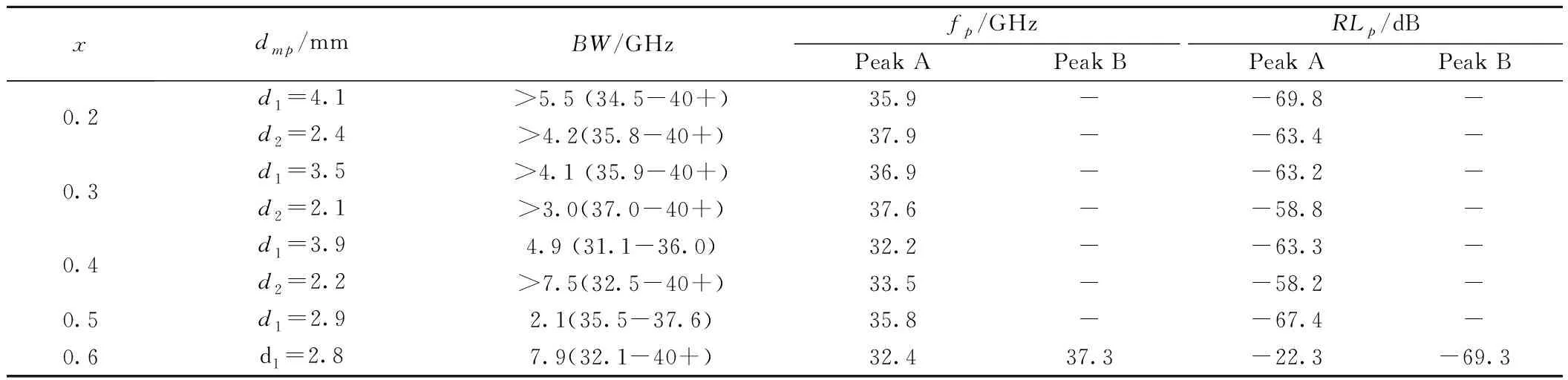
Table 4 Practical matching thickness (dmp), bandwidth (BW), frequency (fp) and intensity (RLp) of the RL peak A at the lower frequency and peak B at the higher frequency of BFVNO with x=0.2-0.6 sintered at 1300 ℃ for 3 h
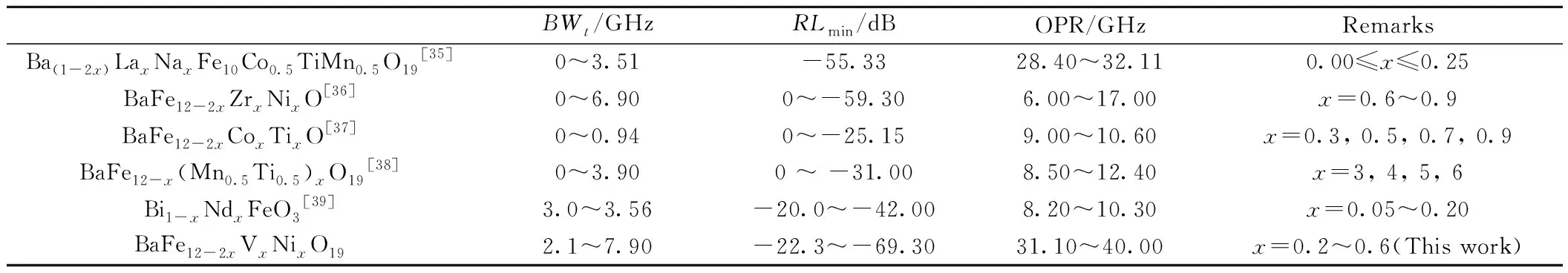
Table 5 Comparison of the absorption properties, BW, RLmin, and operating frequency range (OPR) between BFVNO and the hexaferrite based, as well as other types of, absorbers

Fig. 9 RL of BFVNO (x=0.2-0.8) over the frequency range of 26.5-40 GHz and a thickness range of 0-4.5 mm
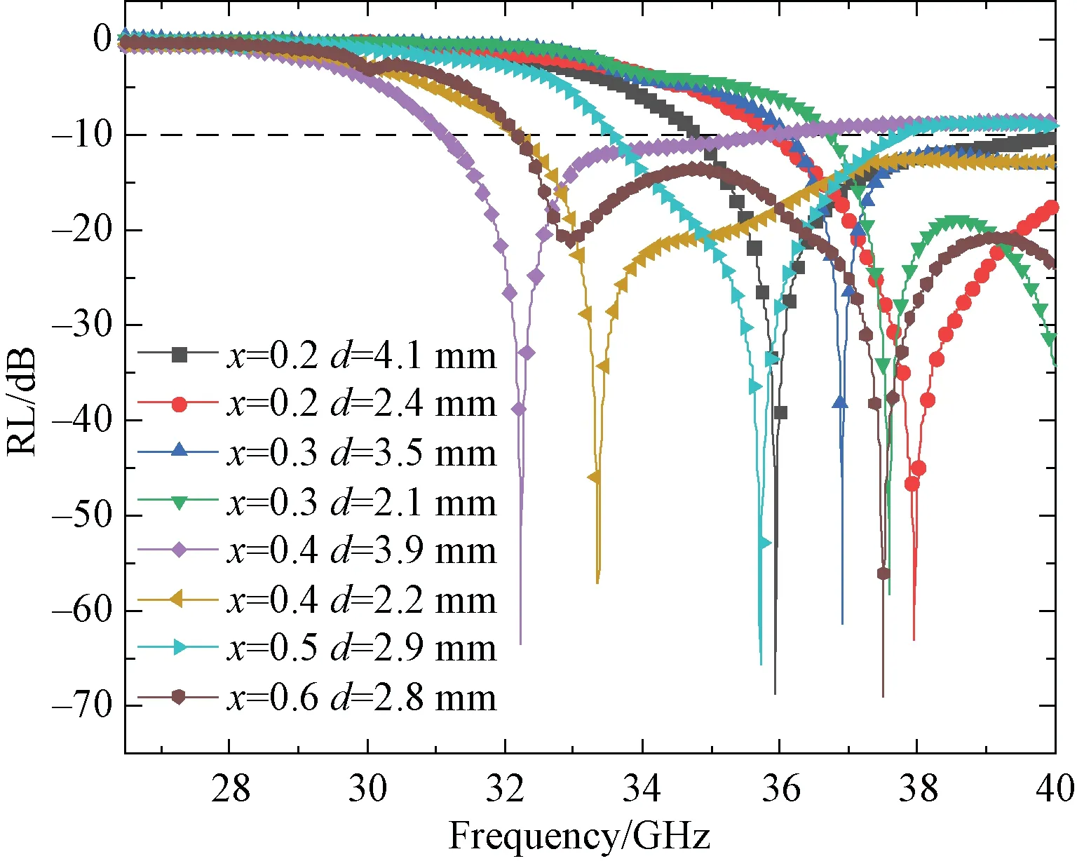
Fig. 10 Plots of RL of the BFVNO (x=0-0.6) with different matching thickness regarding the lower frequency peak as a function of frequency at 26.5-40 GHz
As we know, the EM wave energy absorption and losses are depended on the dipoles (dielectric loss), magnetic loss and the flow of free electrons (conductance loss). As mentioned above, the EM wave energy absorption and losses are mainly from natural resonance, one special mechanism of magnetic loss. Fig.11summarizes the imaginary part of permeability (μ″), attenuation constant (α), RL, and modulus of impedance ratio (|Zin/Z0|) of the BFVNO sintered at1300℃ for3h over26.5-40GHz.αand |Zin/Z0| are calculated by Eq.(6) and (7).
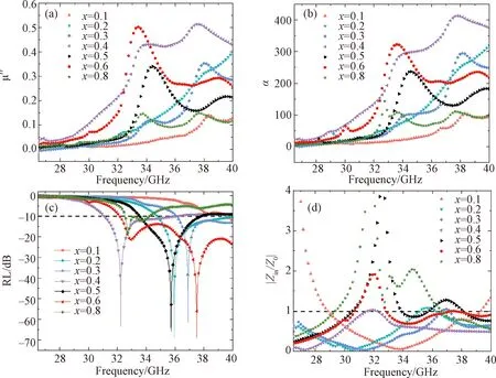
Fig. 11 μ″, α, RL, |Zin/Z0| of the BFVN (x=0.1-0.8) over 26.5-40 GHz
(6)
(7)
Wherefis the microwave frequency,Zinis the input impedance of the absorber,Z0is the characteristic impedance of free space,cis the velocity of light, andερ,μρare the complex permittivity (ερ=ε′-φε″) and complex permeability (μρ=μ′-φμ″), respectively.
It is easy to see that the trend of the attenuation constant of the BFVNO is consistent with that of the imaginary part of the permeability, showing the peaks of natural resonance of BFO, which suggests that the main absorb property origins from the natural resonance. But the RL does not obey the trend of theμ″, on account of the impedance match of the BFVNO. However, according to Eq.(7), the impedance match is depending on both complex permittivity and complex permeability. If the input impedance of BFVNO is close to the characteristic impedance of free space, the RL of BFVNO will achieve a lower value. Further, when the |Zin/Z0| values are close to1and there will be a highα, which revealed over the frequency range where natural resonances reflected inμ″.
4 Conclusion
The replaced amount of Fe3+was increased by V5+-Ni2+co-substituting and then broad bandwidth has been obtained. The hexagonal plate-like barium ferrite with V5+-Ni2+ions substituting for Fe3+ions are realized in the BaFe12-2xVxNixO19withx=0-0.8. And the positive charges induced madeHaof the BFVNO decreased dramatically from 15.66 kOe to about 11.47 kOe. Controlled by the significant decrease inHa, natural resonance peaks shift from 45 GHz to about 35 GHz withxvarying from 0 to 0.8. Multiple natural resonance peaks appear inμ″ due to multiplegfactors contributed by Fe3+ions and exchange coupling between Fe3+and Fe2+, which result in broad bandwidth. When the matching thickness of V5+-Ni2+co-substituted barium ferrites is about 2 mm, the bandwidth can reach about 8 GHz and theRLcan below to about -60 dB. Moreover, the co-substituted barium ferrites can achieve wider tunable frequency range from 3 GHz to above, which makes it a promising absorbing material.
