Plasma treatment for enhancement of the sorption capacity of carbon fabric
2022-01-10IlyaZADIRIEVElenaKRALKINAVladimirSAMOILOVVictoriaELCHANINOVAValentinaGORINAIlyaIVANENKOKonstantinVAVILINandAlexanderNIKONOV
Ilya ZADIRIEV, Elena KRALKINA, Vladimir SAMOILOV,Victoria ELCHANINOVA, Valentina GORINA, Ilya IVANENKO,Konstantin VAVILIN and Alexander NIKONOV
1Physical Electronics Department, Faculty of Physics, Lomonosov Moscow State University, 119991 Moscow, Russia
2 Research Institute for Graphite-Based Structural Materials ‘NIIgrafit’, 111524 Moscow, Russia
Abstract In this work we carried out an experimental investigation into enhancement of the sorption capacity of carbon fabric using plasma treatment methods.Carbon fabric is based on viscose fiber and is hydrophobic by nature.Enhancement of the fabric sorption capacity is required for its application in medicine.For this purpose,two plasma treatment methods were considered,i.e.atmospheric nonequilibrium radiofrequency (RF) discharge and a vacuum RF plasma source with an external magnetic field.Samples treated by atmospheric discharge demonstrated aging effects during the first week after treatment.The sorption capacity of samples treated by the RF plasma source was stable over the same period and reached values as high as 0.95.Parameters of the beam created by the vacuum RF plasma source were analyzed and dependences of the fabric sorption capacity and specific surface area on plasma treatment time were investigated.We found that sorption capacity reached its maximum value after 30 min of treatment and did not change significantly if processing was continued, while the specific surface area reached its maximum after 3 min of treatment and quickly decreased after that.It was found that the micropore structure of the fabric remained almost the same during plasma treatment.The volume of mesopores in a unit of the fabric mass (specific volume) doubled during the first 5 min of treatment and returned to initial values after 30 min of treatment.The sorption capacity continued to increase even when the specific surface area decreased after reaching its peak value.This indicates the important role of surface functional groups formed on carbon fibers during plasma treatment.This is consistent with the results of x-ray photoelectron spectroscopy analysis showing changes in surface oxidation during plasma treatment.
Keywords: carbon fabric, sorption, plasma treatment, radiofrequency
1.Introduction
Plasma surface engineering is an actively developing area of applied physics.Recently it has become an essential component of many industrial processes.Typical plasma treatment technologies are cleaning, surface modification, etching and deposition of coatings.A wide range of plasma sources,operating at both atmospheric and low pressures, have been developed to meet the requirements of industry.A general overview of existing techniques can be found in [1–3].
Carbon fabrics based on viscose fiber are used in medicine for the treatment of burns and purulent wounds.The therapeutic effect of carbon fabrics is due to the sorption of wound secretions and the cleansing from the wound of pus and bacteria.Such a fabric offers advantages when stationary medical help is unavailable as it suppresses sticking to the wound and can be reused.Untreated carbon fabrics are hydrophobic by nature, and their sorption properties are insufficient for medical applications [4].To improve the hydrophilic properties of carbon fabrics and impart sorption properties to them, electrochemical, plasma and other techniques are used [1–3].
Currently there are a large number of ion-beam and plasma methods for enhancing the hydrophilic properties of the surface of various materials, including carbon[5].One of the most popular approaches is the use of a nonequilibrium atmospheric discharge, namely corona, glow discharge,plasma jet or dielectric barrier discharge [6–11].The undoubted advantage of this approach is the relative simplicity and low cost of implementation in comparison with vacuum techniques.The problem, however, is the nonuniformity of the treatment and the pronounced effect of aging.More complex vacuum techniques include the materials treatment in radiofrequency (RF) and microwave discharges [12, 13], as well as their bombardment by an energetic ion beam in the presence of reactive gases [14].A variety of ion sources can be used for this purpose [14–16].The advantage of vacuum technologies is the possibility to accurately control the desired surface treatment parameters due to the opportunity to control the energy and flux density of charged particles bombarding the material’s surface.However, vacuum technologies are fraught with difficulties arising from the need to place the processed sample in a vacuum chamber and are significantly inferior to atmospheric methods in terms of cost.
Hydrophilic plasma treatment of carbon fibers is usually studied in a framework of other tasks, the most popular of which is the enhancement of carbon fiber adhesion to a polymeric matrix in composite materials[17–22].An increase in surface roughness and its oxidation are desirable effects that allow better adhesion and improve the mechanical performance of a composite.Both can be achieved by atmospheric or low-pressure plasma treatment in an oxygencontaining gas mixture.Diblikova et al[19]showed that even treatment in argon can give acceptable parameters.As a result of such plasma treatment, among other effects, carbon fiber usually gains hydrophilic properties, but these tend to fade over time [23].Atmospheric and low-pressure plasma treatment of activated carbon and activated carbon fibers show changes in the porous structure and chemical composition of the material surface [24, 25].
According to modern concepts, enhancement of the sorption properties of plasma-treated surfaces is due to the change in specific surface area(total surface area of a material per unit mass) and to the formation of the functional groups that lead to an increase in surface energy[6,9,10].The latter process is related to the improvement of surface hydrophilicity.For instance, if carbon is treated in an oxygencontaining plasma,C–O and C=O bonds are formed[7,9]on its surface;as a result,the contact angle reduces.It was shown by Watanabe et al [7] that excited neutral particles and radicals(not charged particles)play the main role in the formation of functional groups.
This work describes the results of a study on the modification of the sorption properties of carbon tissue as a result of its treatment with atmospheric discharge plasma and vacuum treatment with a plasma flow emanating from an inductive RF plasma source with an external magnetic field.We present the main parameters of the plasma flow created by the inductive RF source, as well as the main dependences of the sorption capacity of the plasma-treated carbon tissue.
2.Experimental methods
The original carbon fabric used in this work was viscose fiber with an average diameter of 9 μm.An image of the fibers obtained by dual-beam scanning electron microscopy (SEM)with a FEI Quanta 3D FEG is shown in figure 1.The thickness of the fabric is approximately 0.4 mm while the diameter of each fiber is about 9 μm.To determine the sorption capacity of treated carbon fabric it was soaked in a 0.05%water solution of chlorhexidine for a certain amount of time,during which it was periodically extracted from the solution in order to measure the mass of the fabric with adherent liquid.The ratio of the mass of liquidPlto the mass of dry tissuePtfirst grew with time then saturated.The asymptotic value ofPl/Ptwas considered as the sorption capacityCmof the tissue.As a rule, the mass of chlorhexidine absorbed by the fabric reached its steady-state value within 60–90 min of soaking.
The isotherms of nitrogen adsorption by samples after plasma treatment were obtained using an ASAP 2020 instrument (Micromeritics, USA).Then, based on the adsorption isotherms, the specific surface area of the samples was calculated by the Brunauer–Emmett–Teller method[26, 27] and the pore size distribution in the samples was determined using the Horvath–Kawazoe method [28–31].
Enhancement of the fabric sorption capacity was implemented using two methods: treatment in a long atmospheric RF discharge and vacuum treatment in a plasma beam created by an inductive RF plasma source with an external magnetic field.
2.1.Atmospheric plasma treatment device
The scheme of the long plasma source, operating at atmospheric pressure, is shown in figure 2.The plasma source includes an electrode connected to the RF power source through a matching circuit (active electrode), usually in a form of a string, an ignition electrode, a gas distributor that provides uniform blowing of air or another working gas along the active electrode, a grounded electrode, a dielectric holder on one end of the active electrode, which serves as a discharge limiter, and a stepper-motor based mechanical system for moving the processed material through the discharge gap perpendicular to the active electrode with a constant speed.At the initial moment after turning on the RF generator,a nonthermal atmospheric RF glow discharge in the form of a filament is ignited between the ignition and grounded electrodes.Then, carried by a stream of air from the inclined orifices, the velocity of which has a horizontal component(parallel to the string and the grounded electrode), the discharge moves along the string until it reaches the limiter.The velocity of this movement is about 1 m s−1.After reaching the limiter, the discharge cannot move further along the active electrode and becomes stretched by the air stream until it extinguishes.The disappearance of the plasma link between the active and grounded electrodes restores the conditions that were in place before breakdown.This leads to the appearance of another atmospheric discharge between the ignition and grounded electrodes and the whole process repeats itself.This process is shown schematically in figure 3.During operation heating of the treated sample by the discharge is relatively weak, so even materials sensitive to heat can be processed.Uniformity of sample processing is ensured by the constant rate of airflow created by the gas distributor.The speed of the processed material movement can be set from 0.5 to 10 m min−1.
To implement this atmospheric technology for enhancing the sorption capacity of carbon fabric, a sample of carbon fabric was placed on a grounded electrode.A RF generator with an operating frequency of 13.56 MHz was connected to a plasma device through a matching system.The matching system provided RF voltage at the string (active electrode)with an amplitude of at least 10 kV.After the discharge was ignited, the RF voltage amplitude decreased to 3–4 kV.Processing of a carbon fabric sample with an area of 750 cm2was carried out for 2–3 min at an RF generator power of 100 W.
2.2.RF plasma source with an external magnetic field
A schematic of the plasma source is shown in figure 4.It consists of a cylindrical quartz gas-discharge chamber(GDC)with narrowing at the outlet.The GDC is 10 cm long and has a diameter of 4.5 cm.The outlet hole has a diameter of 2.5 cm.The length of the conical part between the cylindrical part of GDC and the outlet is 2.5 cm.A cooled solenoidal antenna-inductor is placed on the side surface of the GDC.A longitudinal magnetic field is created inside the GDC by means of an electromagnet.Magnetic field induction can be varied in the range of 5–100 G.The working gas is supplied to the GDC through a gas distributor located on the surface of the GDC opposite to the outlet.
The plasma source was placed into a vacuum chamber,which was pumped by a rotary and a turbomolecular pump.The residual pressure in the chamber was no worse than 0.03 mTorr (the typical value was 0.01 mTorr).To ignite and maintain the inductive RF discharge, the antenna was connected through a matching system to an Advanced Energy Cesar RF power generator with a frequency of 13.56 MHz.The matching system provided the conditions under which the reflected power was no more than 3% of the forward power.The magnitude of the external magnetic field was chosen from the conditions for the best absorption of the RF generator power by the plasma.The fabric to be treated was placed in a plasma jet created by the source at a distance of 8–10 cm from the outlet.
This kind of plasma source is primarily used in prospective schemes of electric propulsion for spacecraft and is alternatively known as a low-power helicon thruster.For the purposes of plasma treatment, this source was chosen due to its ability to create an electrically compensated ion flow with relatively low average ion energies (50–70 eV) and a dense plasma inside the GDC, necessary to produce excited neutral particles and radicals of the working gas.Ion source operation does not depend on the size, distance to or type of material being treated, which is another advantage.
The parameters of the RF inductive plasma source with an external magnetic field were obtained using argon as the working gas.To study the energy distribution of ions in the plasma flow created by the source, measurements were carried out using a four-grid retarding field energy analyzer located at a distance of 8 cm from the source outlet.The longitudinal distributions of the plasma concentration in the jet created by the source, as well as the distributions of the electron temperature and space potential, were investigated using a movable RF-compensated probe mounted on a linear transmission unit capable of moving the probe along the source axis.
Figure 5 shows the longitudinal distribution of the electron concentration along the source axis.The magnetic field lines outside the GDC had a diverging geometry; therefore,the plasma jet following along the magnetic field lines also diverged.Plasma concentration values fell from about 1010cm−3in the area of the outlet to values of about 109cm−3at a distance of 8 cm from the outlet where the carbon fabric was located.

Figure 1.SEM image of carbon fibers.

Figure 2.Scheme of atmospheric plasma treatment device: 1, RF power source with matching system; 2, grounded electrode in a dielectric (ceramic) tube; 3, active electrode (string); 4, ignition electrode;5,treated sample;6,discharge limiter;7,inclined orifices;8, buffer volume of pressurized air, connected to a compressor.

Figure 3.Stages of discharge in the atmospheric plasma treatment device.

Figure 4.Scheme of inductive RF plasma source: 1, RF power source; 2, matching system; 3, GDC (quartz cylinder with a constriction near the exhaust orifice); 4, gas feeder; 5, spiral RF antenna; 6, electromagnet; 7, vacuum chamber walls; 8, treated fabric sample; 9, grounded metallic casing.

Figure 5.Distribution of plasma concentration n along the source axis (the x coordinate is positive inside the GDC, negative outside and zero at the position of the outlet).Measurements were done with a RF power of 100 W, an argon flow of 12 sccm and magnetic induction of 40 G inside GDC.

Figure 6.Logarithm of directed flat probe current Ip(Up is the probe voltage).The probe is positioned on the axis of the source at a distance of 8 cm from the outlet.Curve 1 corresponds to the probe oriented along magnetic field lines and curve 2 is for the probe normal to them.Measurements were done with a RF power of 150 W, an argon flow of 12 sccm and magnetic induction of 60 G inside the GDC and 8 G in the area of the probe.
Experiments showed that the plasma jet at the exit from the plasma source contained directed flows of both electrons and ions.The energy distribution of electrons outside the GDC in the presence of an external magnetic field was a superposition of two distributions: a Maxwellian isotropic group of slow electrons with a temperature of about 6.5 eV and an anisotropic group of fast electrons with an energy of more than 22 eV.Figure 6 shows the difference between these two groups using an electron current to a directed flat probe.

Figure 7.Distribution of plasma space potential Us along the source axis (the xcoordinate is positive inside GDC, negative outside and zero at the position of outlet).Measurements were done with a RF power of 100 W, an argon flow of 12 sccm and magnetic induction of 40 G inside GDC.

Figure 8.Photo of two carbon fabric pieces after water drops were placed on their surfaces: sample without plasma treatment (left) and sample processed using the atmospheric plasma treatment device(right).

Figure 9.Kinetics of chlorhexidine sorption by carbon fabric samples after plasma treatment for (1) 1 min, (2) 3 min, (3) 5 min,(4) 15 min, (5) 30 min and (6) 50 min.
The average ion energy in the flow generated by the source was in the range of 35–40 eV and did not depend on the main parameters of the discharge(RF power,gas flow rate and magnetic induction) in the considered range of parameters.It should be taken into account that the ion flux arriving at the surface of the sample to be treated consists of two parts: the divergent flux emitted by the source and the flux formed by ions that have passed from the plasma surrounding the sample to its surface through the space charge layer located near it.Particles from the former are accelerated twice: the first time by the electric potential drop on the exit from the source and the second time by the electric field in the space charge sheath near the treated sample.Particles from the latter are only accelerated in the treated sample’s space charge sheath.Measurements of the plasma potential relative to the grounded walls of the vacuum chamber at the location of the fabric sample showed that its values do not exceed 7 V(see figure 7).Taking average ion energies in the ion flow into consideration, we can conclude that the component corresponding to the divergent flux emitted by the source is dominant.
Treatment of carbon fabric in a plasma jet emitted from a plasma source was carried out at a RF generator power of 100–200 W, using oxygen, nitrogen and air as the working gases.The flow rate of the working gases was 10–25 sccm.The working pressure in the vacuum chamber during the operation of the source was 0.6–0.8 mTorr.The treatment time varied from 1 to 50 min.
3.Experimental results
A carbon fabric sample with an area of 750 cm2treated using the long RF plasma source at atmospheric pressure for 2–3 min showed significantly improved sorption properties.Water drops placed on the surface of the treated fabric were immediately absorbed (see figure 8), so it was nearly impossible to measure the contact angle.However, the sorption properties obtained in this way showed an aging effect and quickly degraded over time.This makes this method impractical for enhancing the sorption capacity for medical purposes: during the first day water drops ceased to be immediately absorbed but still had a contact angle of<10°, over a week the contact angle returned to a value of approximately 50° (untreated samples have a contact angle of >90°).
Unlike the samples treated with the atmospheric treatment the samples treated by the RF plasma source showed no pronounced aging effects: during the first 7 days after treatment the sorption remained constant within a 5% margin.
Figure 9 shows the dynamics of carbon fabric sample sorptionCafter treatment for various durations with a RF plasma source, and figure 10 shows the dependence ofCm(asymptotic values ofC)on the duration of treatment.As can be seen, the maximum value of sorption capacityCmis achieved with a plasma treatment duration of about 30 min.
As an important factor in the sorption process, specific surface area was also considered.Figure 11 shows the dependence of the specific surface areaSspof carbon fabric on the duration of plasma treatment.During the first 3 min, a sharp increase inSspis observed, then up tot≤15 min the surface shrinks; laterSspreaches a constant value.
Figure 12 shows the simultaneous change in the sorption capacity and specific surface area during plasma treatment(arrows indicate the direction of the process).It is noteworthy that during plasma treatment, the sorption capacity continues to increase even with a decrease inSsp.This is probably due to the formation of a larger number of polar functional groups on the surface of the tissue.The results also demonstrate the complexity of the carbon fabric surface activation process,when simultaneously with the formation of functional groups transformation of the surface and porous structure occurs.
Figure 13 shows SEM images of carbon fabric fibers in their initial state.There are small grooves on the lateral surface of the fibers.Pores and capillaries are not observed in the cut end of the fiber.

Figure 10.The effect of the duration of plasma treatment on the chlorhexidine sorption capacity Cm of the samples.
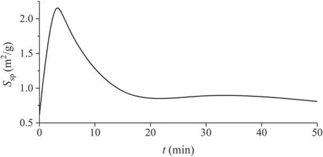
Figure 11.Dependence of the specific surface area Ssp of carbon fabric on the duration of plasma treatment t.
Figure 14 shows SEM images of carbon fabric fibers after plasma treatment for 3, 15 and 50 min, respectively.Already after 3 min of plasma treatment, a large number of pores are observed in the cut end of the fiber.The surface relief of the fiber changes: first, rounded depressions and transverse grooves appear and the longitudinal grooves become deeper; after plasma treatment for 30 min, the relief collapses and the surface becomes smoother.No visible changes in the state of the surface are observed after treatments longer than 30 min.
Figures 15 and 16 and tables 1 and 2 show the characteristics of the porous structure of the carbon fabric.The pore size distribution changes during the course of plasma treatment.The total volume of pores with a diameter of<50 nm in the process of plasma treatment increases up tot= 5 min, then falls.This time is close to the position of the maximum specific surface areaSsp(figure 11), which is located att= 3 min.
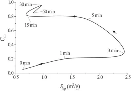
Figure 12.Changes in the specific surface area Ssp and chlorhexidine sorption capacity Cm of the samples during plasma treatment.

Figure 13.SEM images of carbon fabric fibers in their initial state.
It should be noted that the replacement of air as a working gas with pure oxygen does not lead to a significant change in the sorption capacity: upon 30 min of treatment with a RF power of 100 W,the sample treated in air showed a sorption of 0.96 while in pure oxygen the value was 0.85.The treatment in nitrogen under the same conditions leads to values that are half of these, i.e.Cm= 0.45.As it mentioned in the Introduction, in accordance with [5, 7] the sorption properties of the carbon surface treated by the plasma jet are to the greatest extent determined by the concentration and types of functional groups formed on it.The types of functional groups, in turn, depend on the kind of gas used.The main mechanisms leading to the formation of functional groups on the surface of carbon in a plasma are interactions with charged gas particles(ions)and with uncharged particles(radicals and excited particles).The density of the ion flux generated by the source depends significantly on the distance to its axis and is practically absent on the side of the tissue opposite the source.Nevertheless, the difference in the sorption properties between the tissue treated on only one side for 30 min and the tissue treated on both sides for 15 min each side was no higher than 7%.This value is close to experimental error.Such a result indicates the decisive role of uncharged particles, mainly oxygen and nitrogen radicals, in the process of formation of functional groups on the carbon surface.This is consistent with the results obtained in other work [10, 14].
In order to determine the influence of air plasma treatment on the surface chemical composition of carbon fabric,XPS analysis of three samples was carried out: untreated,treated for 5 min and treated for 30 min For the correct interpretation of the XPS results, analysis of the untreated sample by Raman spectroscopy was also carried out.The obtained Raman spectrum (figure 17) has a form closely resembling that of pyrolytic carbon.It has pronounced D and G peaks with positions at 1329 and 1596 cm−1, as well as a wide 2D peak in the region of 2600 cm−1, the intensity of which is much lower than that of the G peak, which is also a typical pattern for graphite.According to[32],the position of the G peak and the ratio of the intensities of the D and G peaks allow the material to be characterized as nanocrystalline graphite.This means that prevalent sp2carbon bonds with a significant concentration of defects (including sp3bonds) are to be expected from the XPS results.From the absence of pronounced peaks in the regions of 1100 and 2100 cm−1, it was concluded that there are no sp1carbon chains on the sample surface.

Table 1.Characteristics of carbon fabric porous structure.

Table 2.Characteristics of the carbon fabric micropore structure after plasma treatment.
The XPS spectra of the studied samples had pronounced C1s and O1s peaks(figure 18),which were deconvoluted into the components presented in table 3.The concentration of nitrogen on the surface of the samples was insignificant (3%or less), therefore it was not taken into account further.In addition to the 284.7 eV peak corresponding to sp2carbon,the C1s peak also contains 283.9 eV and 285.4 eV peaks.Both of these characterize defects in the graphite structure of the sample, the former being responsible for point vacancies(such as pentagon or heptagon rings) [33] and the latter for sp3bonds.The significant magnitude of these peaks indicates that the surface is highly defective, which is consistent with the large relative value of the D band in the obtained Raman spectrum.
It is worth noting that the untreated hydrophobic surface of the first sample is oxidized (the oxygen to carbon ratio is around 20%according to XPS),which may be a consequence of its contact with atmospheric air at high temperatures during the fiber manufacturing process.It can be seen from table 3 that treatment with air plasma for 5 min leads to a significant drop in the relative intensity of the lines corresponding to the bonds of oxygen with carbon, and a longer treatment of 30 min leads to their subsequent growth.In this case, in accordance with figure 10, a decrease in oxygen-containing bonds on the surface of the material in the first 5 min of plasma treatment is accompanied by a sharp increase in its sorption capacity, and by 30 min it reaches saturation.In plasma treatment, two processes are going on in parallel:surface cleaning (its sputtering by ion bombardment and etching by radicals and their ions) as well as surface oxidation.Figure 12 shows that the specific surface area increases sharply in the first minutes of treatment, which is naturally associated with etching of the surface hydrophobic layer and the formation of pores.In this case, the fraction of carbon on the surface should increase, and this is reflected in the obtained XPS spectra.Further, an increase in the specific surface area is replaced by its fall and, ultimately, saturation,which should mean the establishment of a balance between the processes of sputtering,etching and oxidation.Due to the fact that the formation of functional groups on the surface during oxidation proceeds parallel to their destruction during etching and sputtering, the nature of this balance between these processes will determine the concentration of functional groups on the surface of the processed sample and have a significant effect on the maximum achievable sorption value.In turn,this balance should depend on the type of gas used for plasma treatment and the rate of sputtering of the sample surface due to ion bombardment (if present).
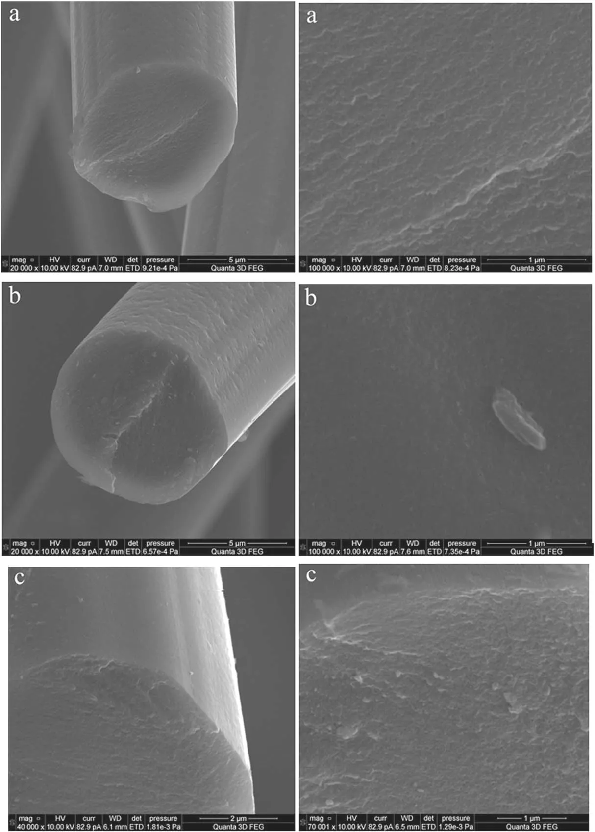
Figure 14.SEM images of carbon fabric fibers after plasma treatment for (a) 3 min, (b) 15 min and (c) 50 min.

Figure 15.Mesopore (pores with a diameter of 20–500 Å) size distribution in the samples of carbon fabric after plasma treatment for(1) 1 min, (2) 5 min, (3) 30 min and (4) 50 min.
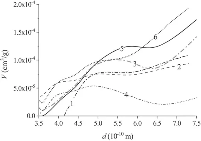
Figure 16.Micropore (pores with a diameter less than 20 Å) size distribution in the samples of carbon fabric after plasma treatment for(1) 1 min, (2) 3 min, (3) 5 min, (4) 15 min, (5) 30 min and (6)50 min.

Figure 17.Raman spectrum of an untreated sample.
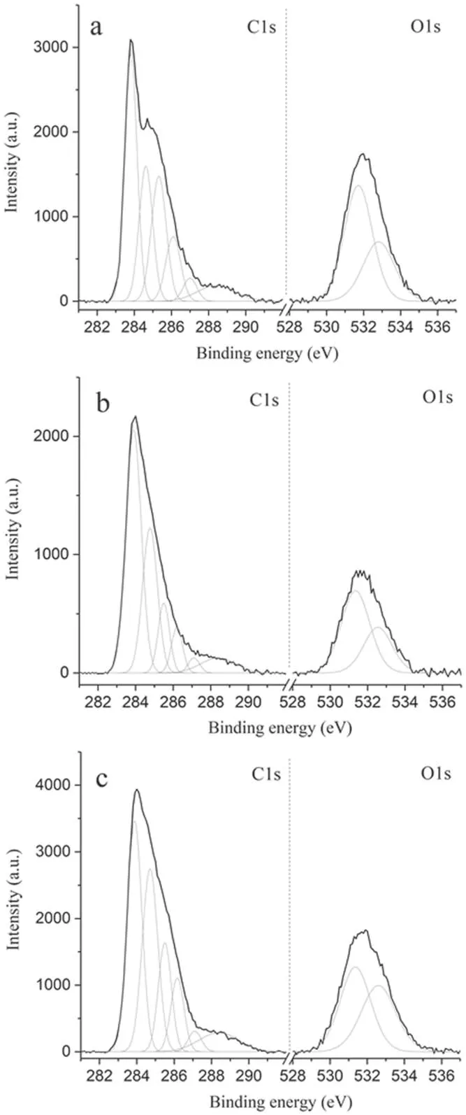
Figure 18.C1s and O1s peaks in XPS spectra of three different samples:(a)no plasma treatment,(b)treated for 5 min and(c)treated for 30 min.

Table 3.The parameters extracted from XPS analysis of the fabric samples with different plasma treatment times.
4.Conclusions
This work has shown the possibility of utilization of a lowpower, low-pressure inductive RF plasma source with an external magnetic field for enhancing the sorption properties of carbon tissues.
Plasma treatment by the atmospheric RF device showed a significant increase in hydrophilicity that was manifested in the immediate absorption of water drops placed on a surface of a treated fabric sample.This increased hydrophilicity decayed over a week so that water drops were no longer immediately absorbed and the contact angle returned to values of about 50°.
Experiments with a low-pressure RF plasma source did not demonstrate any aging effects during the first week,showing that processing of a carbon tissue in an air plasma jet with a density of about 109cm−3and an electron temperature of 6.5 eV makes it possible to increase its sorption capacityCmfrom 0.05 to 0.95.The maximum sorption capacity is reached after 30 min of plasma treatment, while further processing leads to the decrease ofCm.The relative volume of pores with a diameter of up to 500 Å reaches its maximum value after processing for 3 min.The volume of micropores does not change during the treatment.The important result is that the sorption capacity continues to increase with a decrease in specific surface areaSsp, manifesting the role of formation of functional groups, which is also confirmed by XPS analysis.Thus, the sorption properties of carbon fabric are determined by a complex mechanism that can be associated not only with the formation of capillaries and pores in the carbon fiber but also with the filling of the carbon surface with polar functional groups.This distinguishes plasma treatment from the electrochemical treatment commonly used to enhance sorption of carbon fibers.The increase ofCmin electrochemical technology occurs mainly due to the formation of pores of a certain distribution in the filament volume.
Acknowledgments
This work was supported in part by M V Lomonosov Moscow State University Program of Development.The authors acknowledge the ‘Sernia Engineering’ company for support with SEM imaging of the carbon fiber.This work was partially carried out with the support of the Research Facility Center at the Institute of Solid State Physics of RAS.We are grateful to A V Pavlikov (Faculty of Physics, M V Lomonosov Moscow State University) for conducting Raman/FTIR measurements.The experiments were performed using the equipment of the Center of User’s Facilities of M V Lomonosov Moscow State University.
杂志排行
Plasma Science and Technology的其它文章
- Numerical simulation of nanosecond laser ablation and plasma characteristics considering a real gas equation of state
- The propagation dynamics and stability of an intense laser beam in a radial power-law plasma channel
- Effect of edge magnetic island on carbon screening in the J-TEXT tokamak
- Relativistic effect on synergy of electron cyclotron and lower hybrid waves on EAST
- Influence of the X-point location on edge plasma transport in the J-TEXT tokamak with a high-field-side single-null divertor
- A simulation study of protons heated by left/right-handed Alfvén waves generated by electromagnetic proton–proton instability
