Probe method to measure the electromagnetic field in a plasma by Poynting vector conversion
2022-01-10LishanTIAN田丽山WeiminBAO包为民YanmingLIU刘彦明ChaoSUN孙超andChengweiZHAO赵成伟
Lishan TIAN (田丽山), Weimin BAO (包为民), Yanming LIU (刘彦明),Chao SUN (孙超)and Chengwei ZHAO (赵成伟)
1School of Aerospace Science and Technology, Xidian University, Xi’an 710126, People’s Republic of China
2 Plasma Electromagnetic Physics Laboratory (PEPL)in Extreme Environment,the Key Laboratory of the Ministry of Education of China, Xi’an 710126, People’s Republic of China
Abstract In this paper, a high-precision electromagnetic measurement system suitable for a hightemperature and high-speed plasma is built to provide a platform for scientific research on the interaction mechanism of the electromagnetic fields and a plasma.This paper presents a method to measure the electromagnetic field inside a plasma by using a probe and Poynting vector conversion, which is a new and completely different method from the traditional method of measuring the electromagnetic field inside plasma.In addition,for this system and method, this work designs a microstrip antenna probe that can suppress multipath effects.This method is confirmed to be valid and usable after closed-loop verification by the CST software.
Keywords: electromagnetic measurement system, scattering parameters, Poynting vector,microstrip antenna probe
1.Introduction
After a spacecraft enters the atmosphere at a super high-speed from an orbit around the Earth, due to aerodynamic heating,the temperature rises sharply,and the air is ionised to produce plasma.The charged particles in the plasma absorb, reflect,and scatter electromagnetic waves, causing a series of electromagnetic effects that attenuate and interrupt the radio communication between the return capsule and the outside world;this is known as the‘black barrier’problem[1,2].The‘black barrier’problem has become a worldwide problem that restricts the development of high-speed aircraft in nearby space, and a series of projects represented by the American Rolling Airframe Missile project have carried out theoretical research, flight tests and ground simulation experiments[3–5].At the same time, many scholars have also proposed ways to alleviate this problem [6–8].But it is impossible to completely solve the black barrier problem.Therefore, to study the interaction mechanism between electromagnetic waves and plasma, it is necessary to measure the changes in the electromagnetic field inside the plasma with great precision and a high space-time resolution.
At present, there are few methods available for measuring the electromagnetic field present inside a plasma.Kitisriet al[9] used a Hall probe with a measurement system to measure the internal magnetic field of the plasma and compensated the terminal magnetic field by adjusting the terminal current to obtain a good lateral field area of 19 mm.Meyeret al[10] used an induction loop probe to measure the time derivatives of the axial and radial components of the electric field when using an argon plasma, thereby calculating the approximate components of the induced electric field.In addition, there are other measurement methods available,such as measuring the change in plasma temperature to derive the microwave electric field intensity [11–13].At present,most of scholars have proposed a variety of methods for measuring the electromagnetic field present inside plasma;the methods typically use miniature probes and coils to build a closed loop and infer the conductive magnetic field through the measurement of current and voltage.Most of them are used to measure the self-generated tiny electromagnetic field in the plasma, which is not suitable for the measurement of the electromagnetic field when the electromagnetic wave propagates in the plasma, and it is even less suitable for the measurement of the electromagnetic field inside the plasma of high-speed targets.Because the main idea of this type of method is to build a closed circuit outside the measurement environment, and to push the conductive magnetic field through the current and voltage in the circuit.There are two reasons why this method is not applicable: first, the huge experimental chamber environment makes it impossible to build the circuit outside;second,if the circuit is built inside,it is difficult to protect the entire circuit from high-temperature.
Therefore, this work builds a high-precision electromagnetic measurement system suitable for a high-speed target plasma.The system is used for the high-precision and hightemporal resolution measurement of changes in electric and magnetic fields during the evolution of plasma electromagnetic wave propagation.The probe module used in the system, combined with the experimental environment, is specially designed.This paper uses the method of connecting a microstrip antenna with the inner conductor of a coaxial probe to form a new type of probe, which effectively suppresses the influence of the multipath effect in the system.In addition, a new method of measuring the electromagnetic field inside the plasma is proposed.This method uses an electromagnetic field probe to move the receiving antenna signal in the plasma area to measure theS21parameter,which is the forward transmission coefficient, and to obtain the electromagnetic field distribution through a Poynting vector calculation.Poynting vector is the energy flow density vector,and the power per unit area of the energy radiated by the antenna in the far-field area can be calculated and expressed by the average Poynting vector.The physical principle of this method is to equate the electromagnetic wave received by the electric field probe to a plane wave,and then calculate theS21at this place through the Poynting vector derivation to obtain the electromagnetic field here; the probe moves and receives each positionS21,and finally obtains the electromagnetic field distribution of each position.The CST software verifies that the method is effective and usable.CST is a 3D electromagnetic field simulation software, whose full name is‘Computer Simulation Technology’.It can cover the entire electromagnetic frequency band and provide complete timedomain and frequency-domain full-wave electromagnetic algorithms and high-frequency algorithms.Finally,the article verifies the feasibility and accuracy of the method.The rest of this paper is organised as follows.Section 2 presents the idea behind the construction of the plasma internal electromagnetic field measurement system.Section 3 proposes the principle of the Poynting vector method to derive the electromagnetic field inside the plasma,which is the core content of the article.Section 4 presents the probe design used in this method and uses it to verify the above principles in the CST software.Section 5 summarises the article.
2.Electromagnetic field measurement system in plasma
As mentioned earlier, the purpose of this paper is to measure the electromagnetic field inside a high-speed target plasma.Therefore, the plasma generating device used when building the plasma internal electromagnetic field measurement system is an inductively coupled plasma device, and its working principle [14] is shown in figure 1.The plasma generated by the inductively coupled plasma wind tunnel can last longer than the plasma generated by a shock tube[15](usually more than 3000 s), and the former has a more stable plasma jet,which is more conducive to electromagnetic wave transmission characteristic experiments.Compared with the glow discharge device [16], the electron number density of the inductively coupled plasma jet has a wider range, reaching 1010–1013cm−3, and the collision frequency is higher,reaching 109–1010Hz.These parameters are close to the plasma sheath parameters when an aircraft enters the ‘black barrier’, which is more conducive to the re-entry of the aircraft into the atmosphere.
Based on this, a plasma internal electromagnetic field measurement system is built, and its overall frame and the main part of the measurement system built in the real environment are shown in figures 2 and 3, respectively.The signal generated from port 1 of the vector network analyser passes through the transmission line to the horn antenna, and the energy is radiated from the horn antenna;the electric field probe enters the plasma from the far end and moves near the horn antenna along the guide rail; the signal received by the electric field probe is sent through the transmission line to the low-noise amplifier and finally transmitted to port 2 of the vector network analyser, which outputs theS21parameter.In addition, there is a main control computer outside the rack,which is responsible for controlling the transmission of the vector network signal and the movement of the guide rail.At the same time, the computer comprehensively processes the data received by the probe.
3.S21 and the electromagnetic field
3.1.S21 and the average Poynting vector
The final measured data of the plasma internal electromagnetic field measurement system is theS21parameter measured by the vector network analyser.Therefore, it is necessary to connect this parameter with the electric and magnetic fields.S21is the insertion loss, which means how much energy is transmitted to port 2, and it is defined by formula (1)

The energy flow of electromagnetic waves in space is defined by the Poynting vector.The Poynting vector is the power that can be obtained or produced per unit area.The power per unit area of the energy radiated by the antenna in the far-field area can be calculated and expressed by the average Poynting vector,Sav, which represents the average energy of the radiation field passing through a unit area within a certain period of time,that is,the rate of the electromagnetic field energy at the receiving end of the probe.However, the entire length of the exposed conductor in the probe can receive the electromagnetic field, so the probe does not receive energy radiation at a single point.Thus, the average Poynting vector as an average value is not an accurate value of the received electromagnetic field but a relatively accurate value due to the small electromagnetic field receiving area.
According to the simple diagram of the electromagnetic field measurement system in figure 4, the electromagnetic field energy received by the inner conductor at the upper end of the probe reaches the vector network analyser to receive and displayS21parameters after passing through a link.Therefore, the received power of the vector network analyserPReceiveis equal to the electromagnetic field energy received by the inner conductor, that is, the average Poynting vector plus the gain of the probeGProbe, minus the loss of the transmission lineLOSSLine, plus the gain of the low-noise amplifierGLNA, as shown in formula (2)

We know the transmitting power set by the vector network analyser,and the receiving power of the vector network analyser can be obtained according to formula(1);the gain of the low-noise amplifier is also known as the set value,and the transmission loss and probe gain can be measured.Therefore,substituting formula (1) into formula (2) we obtain the relationship betweenSavandS21:

3.2.Sav from the electric and magnetic fields
For the derivation ofSavfrom the electric and magnetic fields,the definition of the Poynting vector is converted into a complex form, as shown in formula (4):

The average Poynting vector is defined as:

When the microstrip antenna on the top of the probe receives electromagnetic waves, it can be equivalent to a plane wave due to the small size of its patch.According to the fact that the electric field vector in a plane wave is equal to the magnetic field vector multiplied by the wave impedance[17],formula (4) is substituted into formula (5) to obtain the following formula:
Substituting the definition of η, the wave impedance,which is the ratio of electric field strength to magnetic field strength, into formula (6) yields:

In formulas (7) and (8),Savis measured in section 3.1,and there are two parameters, permittivity ε and permeability μ, which are both quite important parameters describing the characteristics of the plasma medium.Plasma is a nonmagnetic medium,so its relative permeability μris equal to 1.The relative permittivity εrof the plasma is determined by the movement of electrons and ions,and[18]gives the derivation result:

Now that we know εrand μr, we can obtain ε and μ.In addition, in formula (9),eandmeare the charge and mass of the electron,ω is the working frequency,andNand νeare the density and collision frequency of the plasma, respectively.Substituting them into formulas (7) and (8), the values of the electric and magnetic fields can be obtained.
4.Probe method verification
4.1.Probe design
In the third section, the theoretical basis of the probe method for measuring the internal electric field of the plasma is given.Therefore, it is necessary to verify the effectiveness and accuracy of the method in a closed loop.However, because the metal inner wall of the internal electromagnetic field measurement system built in section 2 induces the influence of multipath effects [19], the probe used in the system needs to be specially designed.
Obviously, ordinary coaxial probes cannot avoid multipath effects due to their omnidirectionality.Therefore, this article adopts the method of connecting the microstrip antenna with the inner conductor of the coaxial probe to design a new type of probe [20], which meets the system requirements by virtue of the unidirectional radiation characteristics of the microstrip antenna.When designing the electric field probe, to be more suitable for the built measurement system and achieve the best radiation effect of the microstrip antenna,the microstrip antenna module used in the probe is different from a traditional microstrip antenna.The electric field probe structure is shown in figure 5.The metal patch of the microstrip antenna is located in the middle of the surface of the dielectric substrate, the feed line is placed on the back of the patch, a hole is drilled through the centre of the patch to the back to connect the feed line,and the ground plate is placed inside the dielectric instead of on the back.The lower part of the probe is a common coaxial probe with a length of 200 mm;the upper part is a microstrip antenna,with a dielectric substrate made of FR-4 material, with a length of 38 mm,a width of 8 mm,and a thickness of 2 mm;the length of the metal patch of the microstrip antenna, which is 3 mm wide, is 15 mm.The new probe relies on the directional radiation principle of the microstrip antenna [21, 22], which enables the new probe to receive signals in one direction to suppress the influence of multipath effects.Figure 3(b)shows a photograph of the probe on the right,including an enlarged view of the upper half of the microstrip antenna.
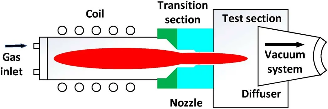
Figure 1.The principle of the inductively coupled plasma device.
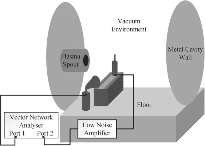
Figure 2.The plasma internal electromagnetic field measurement system.
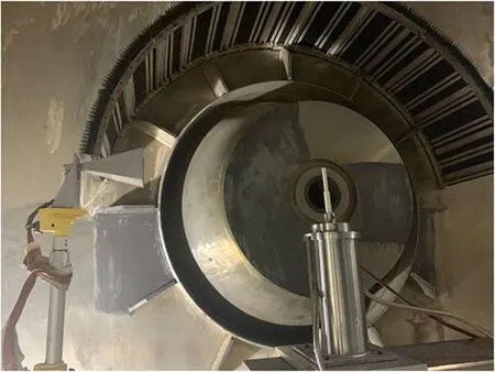
Figure 3.The main part of the measurement system.
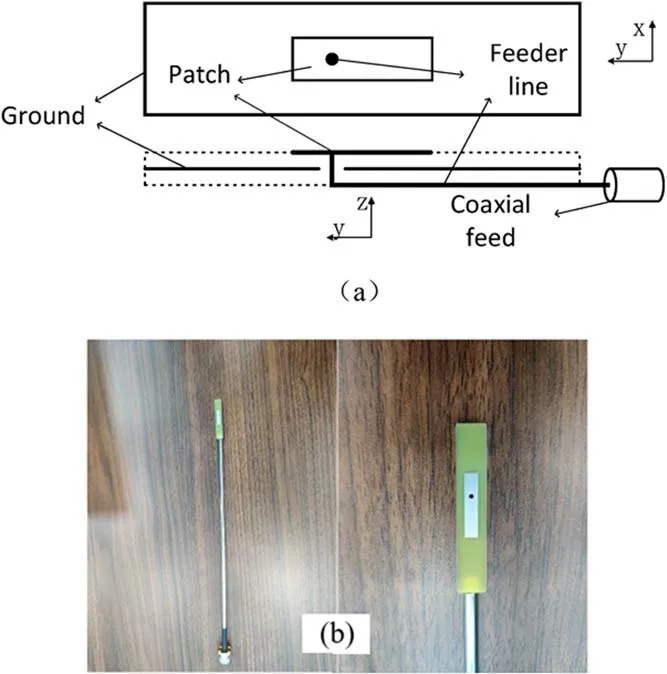
Figure 5.Structure diagram (a) and photograph (b) of the probe.
The new probe uses CST software modelling analysis,and theS11parameter curve of the probe is obtained by simulation in the 3–6 GHz frequency band, as shown in figure 6.The change inS11indicates that the antenna performance is good.The resonance point of the antenna is near 4.8 GHz, and antenna resonance points of different frequencies can be obtained by changing the relative position of the feeding point and the metal patch.Figures 7(a) and (b)show the far-field energy changes of the probe top view and the front view in the 3D and 2D views at 4.8 GHz, respectively.It can be seen from the two pictures that the metal patch surface of the probe microstrip antenna exhibits stronger radiation than the back surface.The simulation shows that the probe has good directivity,which can effectively solve the application requirements of the one-way signal receiving probe.In addition, from the far-field gain Abs (Absolute value)in figure 8,the main lobe magnitude is 3.48 dBi,which is the antenna gain and needs to be used in the next section.

Figure 6.S11 curve change chart.
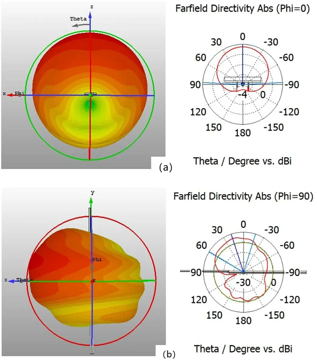
Figure 7.The far-field energy changes of the probe top view (a) and the front view (b) in the 3D and 2D view at 4.8 GHz.

Figure 8.Far-field gain Abs.
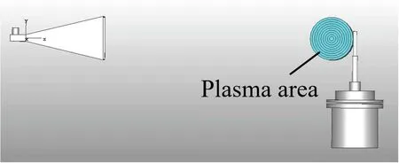
Figure 9.The plasma internal electromagnetic field measurement system in CST.

Figure 10.The S21 curve at 4.8 GHz measured by the probe.

Figure 11.The plasma internal electric field distribution curve 1 measured by the probe method and plasma internal electric field distribution curve 2 obtained by direct simulation.
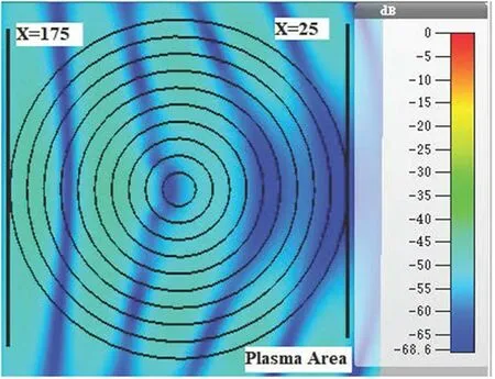
Figure 12.The electric field distribution inside the plasma.
4.2.Method feasibility verification
Now, the probe designed in the previous section is used to verify the proposed measurement method with the CST software.The probe measures theS21parameter change curve when the probe moves in the plasma and calculates the electric field amplitude change curve; in the same simulation environment,when there is no probe in the plasma, the CST software can directly simulate the electric field distribution in the plasma area and take the horizontal electric field when measuring the probe to obtain the second electric field amplitude change curve.The comparison of the two curves can verify the accuracy of the probe method to measure the electric field.
The role of the low-noise amplifier is to amplify the signal attenuated by the system in the real experiment to facilitate monitoring, while the device can be omitted in the simulated environment.At the same time, the transmission line can also be omitted in the simulation environment;therefore, formula (3) is simplified to:

CST software builds the plasma internal electromagnetic field measurement system, as shown in figure 9.To improve the realism of the experiment, the ‘rear metal wall’ module was added to simulate the experimental environment,and the plasma was treated in layers.The plasma was divided into 9 layers, and the plasma density gradually decreased from the inside to the outside.The plasma diameter was set to 150 mm,and the characteristic frequencies corresponding to the plasma density were set to 0.5 GHz, 1.5 GHz, and 2 GHz… 4.5 GHz from the outside to the inside, and the collision frequencies are all 4 GHz.The electric field probe moved within the plasma to obtain theS21change curve composed of 21 positions at a frequency of 4.8 GHz as shown in figure 10.
The transmit power of the antenna is set to 1 W, and the gain of the probe is 3.48 dBi, as given in section 4.1.According to formulas(9),(10)and the parameter table of the 21 positions of the probe, as shown in table 1, the electric field amplitude of each point is calculated, and electric field curve 1 in figure 11 is finally obtained.Considering the shortcomings of the CST software solver, too many measurement points set by the probe at different positions cause the simulation time to be too long, and the final curve drawn by the 21 points cannot be completely continuous.
The probe was removed under the same simulation environment,and the electric field distribution inside the plasma was obtained,as shown in figure 12.It can be clearly seen that the electric field energy drops significantly after passing through the central region of the plasma.The horizontal electric field is taken when the measuring probe is used to obtain the electric field curve inside the plasma,as shown in electric field curve 2 in figure 11.The plasma region is betweenx=25 andx=175,and the plasma centre is atx=100.When entering the first half of the plasma, the electric field should gradually decrease,similar to curve 1;in contrast,curve 2 is used as a reference but fluctuates in this area, and the attenuation trend is not obvious.The reason for this phenomenon is that the ‘rear metal wall’module is added to the simulation environment, and the designed probe shields the rear reflected signal by virtue of its unidirectionality.Even when there are no components to measure internally,the electric field at each point is also affected by the existence of multipath effects.In the second half of the plasma, both curves drop sharply.With the gradual increase in the plasma density,the amplitude of the electric field attenuation gradually increases, and the amplitude of the decrease after passing through the plasma centre is still large.The multipath effect has little influence on the electric field attenuation trend,and the two curves are basically in agreement.In general,if there is no multipath effect, the two curves are more consistent.However, at the same time, the probe suppresses the multipath effect, which is its advantage in real situations.

Table 1.The parameter table of 21 positions of the probe.
5.Conclusion
In this paper, a high-precision electromagnetic field measurement system suitable for high-speed target plasma is built to study the interaction between plasma and electromagnetic waves.Due to the particularity of the system environment,the probe is specially designed in this paper.This paper uses the method of connecting the microstrip antenna with the inner conductor of the coaxial probe to form a new type of probe.Compared with the traditional coaxial probe, the interference received by this probe is significantly reduced.Therefore,the former probe suppresses the influence of the multipath effect in the system.For the precise measurement of the internal electromagnetic field of the plasma, this paper proposes the probe method to measure the internal electromagnetic field and conducts a closed verification.The probe moves in the system to measure theS21parameter change, which is converted into an electromagnetic field by the Poynting vector,and the electric field amplitude in the horizontal direction of the plasma centre is obtained.This article uses the CST software to verify the effectiveness of the method, and the microstrip antenna probe and the measurement method have been implemented in practical engineering applications with good results.
Acknowledgments
This work is supported by National Natural Science Foundation of China (No.61627901).
ORCID iDs
杂志排行
Plasma Science and Technology的其它文章
- Numerical simulation of nanosecond laser ablation and plasma characteristics considering a real gas equation of state
- The propagation dynamics and stability of an intense laser beam in a radial power-law plasma channel
- Effect of edge magnetic island on carbon screening in the J-TEXT tokamak
- Relativistic effect on synergy of electron cyclotron and lower hybrid waves on EAST
- Influence of the X-point location on edge plasma transport in the J-TEXT tokamak with a high-field-side single-null divertor
- A simulation study of protons heated by left/right-handed Alfvén waves generated by electromagnetic proton–proton instability
