Enhanced Performance and Durability of High-Temperature Polymer Electrolyte Membrane Fuel Cell by Incorporating Covalent Organic Framework into Catalyst Layer
2021-09-28LiliangTianWeiqiZhangZhengXieKaiPengQiangMaQianXuSivakumarPasupathiHuanengSuInstituteforEnergyResearchJiangsuUniversityZhenjiang03JiangsuProvinceChina
Liliang Tian , Weiqi Zhang , Zheng Xie , Kai Peng , Qiang Ma , Qian Xu , Sivakumar Pasupathi ,Huaneng Su ,* Institute for Energy Research, Jiangsu University, Zhenjiang, 03, Jiangsu Province, China.
2 South African Institute for Advanced Materials Chemistry, University of the Western Cape, Bellville 7535, South Africa.
Abstract: Proton exchange membrane fuel cells (PEMFCs)are considered one of the most promising technologies for efficient power generation in the 21st century. However,several challenges for the PEMFC power technology are associated with low operating temperature, such as complex water management and strict fuel purification. PEMFC operating at high temperature (HT, 100-200 °C) has in recent years been recognized as a promising solution to meet these technical challenges. At present, HT-PEMFC based on phosphoric acid (PA)-doped polybenzimidazole (PBI) is considered to be the trend of PEMFC future development due to its good environmental tolerance and simplified water/thermal management. In this HT-PEMFC system, the proton transfer in both catalyst layer (CL) and membrane relies on liquid PA. Thus, a proper amount of PA is required to impregnate the membrane and the CL in order to achieve good proton conductivities in an HT-PEMFC system. Therefore, reducing the loss of PA electrolyte in the membrane electrode assembly(MEA) is crucial to maintaining the good durability of HT-PEMFC. In this work, a Schiff base networks (SNW)-type covalent organic framework (COF) material is proposed as the CL additive to enhance the durability of HT-PEMFC. The well-defined porous structure and tailored functional groups endow the proposed COF network with not only excellent PA retention capacity but also good proton transfer ability, thus leading to the superior durability of the HT-PEMFC in an accelerated stress test (AST). After 100 h operation at heavy load (0.2 V) and high flow rate of airpurge, the accumulative PA loss of the COF-based MEA was ~4.03 mg, which is almost an order of magnitude lower than that of the conventional MEA (~13.02 mg), consequently leading to a much lower degradation rate of current density (~0.304 mA·cm-2·h-1) than that of the conventional MEA (~1.01 mA·cm-2·h-1). Moreover, it was found that the electrode incorporating a proper amount (5%-10%,mass fraction) of the COF material possessed a higher electrochemical surface area (ECSA) and lower ohmic and charge transfer resistances, which further improved the performance of the HT-PEMFC. At the usual operating voltage of 0.6 V,the current density of the MEA containing 10% COF was up to 0.361 A·cm-2, which is ~30% higher than that of the conventional MEA at 150 °C, H2/Air and ambient pressure. These results indicate that incorporating COF materials into CL is a promising strategy to enhance the performance and durability of HT-PEMFC.
Key Words: High temperature polymer electrolyte fuel cell; Membrane electrode assembly;Covalent organic framework; Phosphoric acid leakage; Durability
1 Introduction
Polymer electrolyte membrane fuel cell (PEMFC) is considered as one of the most promising technologies for efficient power generation in this century. However, the popularization of PEMFC is currently restricted by several challenges, such as strict fuel processing to remove CO, complex water and heat management, which make the PEMFC systems voluminous, heavy, costly and in most cases complex1-3.Elevating the operating temperature of PEMFC has been recognized as an ideal solution to meet these technical challenges associated with low temperature (< 80 °C)4,5. High temperature (HT) PEMFCs based on phosphoric acid (PA)-doped poly[2,2’-(m-phenylene)-5,5’-bibenzimidazole] (PBI) or poly[2,5-benzimidazole] (ABPBI) membranes, with the operating temperature of 140-200 °C, are so far the most successful candidates in this field6-8. Differing from the Nafionbased low temperature PEMFCs, the proton transfer in HTPEMFC relies on liquid PA. Therefore, a proper amount of PA is required to impregnate the membrane and the catalyst layer (CL)in order to achieve good proton conductivities in a HT-PEMFC system9. However, the liquid PA tends to leach during operation,especially at high current densities, due to a possible steam distillation mechanism resulted from the combination of high temperature and water generation10. The loss of PA electrolyte could increase the resistance for proton transfer in both CL and membrane, as well as decrease the triple-phase boundaries(TPBs) for the electrochemical reactions occurring on the catalyst sites11. Therefore, PA loss during the operation has been considered a major factor for the performance degradation of HT-PEMFC12-14.
To reduce the loss of PA, several attempts have been made by introducing solid acid salts and inorganic fillers into the CL or the membrane as a matrix to increase PA uptake and proton conductivity15-18. Materials such as Al2O315, zirconium hydrogen phosphate16, silicotungstic acid18and phosphotungstic acid17have been investigated in this respect.Although improvements on stability were observed in these works, in most cases the cell performances were inferior to the routine HT-PEMFCs, which were probably due to the poor compatibilities of these inorganic additives with the polymer membranes and polymer ionomers in the CLs, thus resulting in poor interfacial contact between the membranes and the CL,thereby increased cell resistances in these cases17-19. Therefore,maintaining decent fuel cell performance is desired for these PA uptake materials being more widely considered for HT-PEMFC applications.
In recent years, newly emerged porous materials of covalent organic framework (COF) have shown great potential for PEMFC application due to their custom-design functionalities,fine-tunable pore size, high porosity and surface area, as well as their excellent stability in PEMFC operating conditions such as high temperature (up to 300 °C) and strong acid20,21. Generally,these organic polymers have good compatibilities with polymer ionomers in CL and polymer membranes due to their tailored functional acidic or basic groups such as carboxyl, amino and phosphonate groups22,23. More importantly, the well-defined porous structure can offer the COFs superior ability to accommodate guest molecules (such as H3PO4), based on which multiple pathways for rapid proton transport can be created.Inspired by these advantages, a Schiff base networks (SNW)-type COF network was prepared in this work and was proposed to be incorporated into CL to reduce the PA loss in the membrane electrode assembly (MEA). The major cavity diameter (~0.46 nm) of the COF network is well matched with the size of H3PO4molecule (~0.37 nm), then the H3PO4molecules can be effectively confined in these cavities with low leaching rate. It is envisaged that this COF network possesses the PA retention and proton transfer abilities simultaneously, as well as the good compatibility with the polymer membrane, which could then effectively enhance the performance and durability of HTPEMFC.
2 Experimental
2.1 Synthesis of SNW-1 COF network and physical characterizations
The SNW-1 COF network are synthesized as described in literatures21,23. Briefly, melamine (AR, Aladdin),terephthalaldehyde (AR, Aladdin), and anhydrous dimethyl sulfoxide (AR, Aladdin) were added into a three-necked flask with a condensation device. The mixture was then reacted in argon atmosphere for 72 h at 180 °C. After cooling down, the precipitate was separated by filtration and sequentially washed with N,N-dimethylformamide (AR, Aladdin), methanol (AR,Aladdin), and tetrahydrofuran (AR, Aladdin). Finally, the SNW-1 COF network was obtained by vacuum drying overnight at 120 °C.
The Fourier transform infrared (FT-IR) spectra of the COF material was recorded by using spectrometer (Nicolet iS50 FTIR), and the pore size distribution and surface area were measured by N2absorption with a Tristart II gas adsorption analyzer.
2.2 Fabrication of gas diffusion electrodes (GDEs)
The catalyst ink was prepared by ultrasonic dispersing the 40% Pt/C (Johnson Matthey, USA), lab-made 5%poly(vinylidene fluoride) (PVDF) solution and the SNW-1 COF into appropriate amount of dimethylacetamide (DMAc) solvent.The dispersion mixture was ultrasonicated for 40 min for homogeneity before being used.
To prepare the GDEs, carbon papers (TGP-H-090, Toray,Japan) with microporous layer (MPL) were prepared as described in our previous work8. The as-prepared catalyst ink was then sprayed onto the MPL to form the CLs for both cathode and anode GDEs. Afterwards, the GDEs were heat-treated at 165 °C oven overnight to evaporate the remaining DMAc. The Pt loadings of all GDEs (both anode and cathode) used for this study are 0.7 mg·cm-2, and the binder contents (PVDF) in the CLs are 15%. The active area of the GDEs is 2 cm × 2 cm.
2.3 MEA and Single-cell test
PBI membrane (AP-30, Fuma-Tech, Germany) was used in this work. For doping with PA, the membranes were immersed in 85% PA for 6 hours at 130 °C, which gave the membrane an acid doping level of ~300% (based on dry membrane). Before being used, the membrane was taken from the PA bath, and the superficial acid onto the membrane was thoroughly wiped off with lab tissue.
Together with gaskets made of fluorinated polymer, the MEA was assembled by sandwiching the doped PBI membrane between two GDEs in a single cell fixture (Fuel Cell Technologies, Inc., USA) without a preceding hot-pressing step.The single cell performance was evaluated in a fuel cell test system (Arbin Instruments, USA). High pure hydrogen and compressed air were introduced into the anode and the cathode respectively, with flow rates of 0.2 L·min-1(H2) and 0.4 L·min-1(air), at ambient pressure. Both H2 and air were used as dry gases, directly from the compressed bottles without external humidification. Prior to testing, the MEAs were activated by operating the unit cell at a constant voltage (0.55 V) under the cell temperature of 150 °C until a stable performance was obtained. The current-voltage polarization curves were obtained by measuring the current density with the stepwise decrement of voltage from 0.9 to 0.2 V, with an interval of 0.05 V. At each cell voltage, the current was measured after a hold time of 5 minutes to allow the cell approaching steady state.
2.4 Durability test and PA loss analysis
For the durability test, an accelerated degradation technique(ADT) was adopted to evaluate the performance stability during short-term operation (~100 h). Specifically, the HT-PEMFC was operated at 150 °C and heavy-duty condition (0.2 V) to accelerate the PA loss during short-term operation. For the same purpose, compressed air with high flow rate (1.2 L·min-1) was introduced to cathode during durability test.
To quantify the PA loss, a 100 mL bottle containing 50 mL ultrapure water was connected to the gas outlet of the cathode.The leached PA from MEA was collected by passing the exhaust through the ultrapure water in the bottle. The concentration of PA in the water was analyzed every 24 h by ICP-AES.
2.5 Electrochemical characterizations
An electrochemical workstation (CHI660E, Shanghai Chenhua Instruments Co., China) was used in electrochemical characterization. Electrochemical impedance spectroscopy(EIS) was used to study polarization resistance of the MEA. EIS was performed at 0.6 V in range of 0.1 Hz-20 kHz frequency.And cyclic voltammetry (CV) was performed to determine the electrochemical surface area (ECSA) of the Pt/C catalyst. CV was performed in the range of 0.05-1.2 V at a scan rate of 50 mV·s-1by purging dry hydrogen and nitrogen to the anode and cathode, respectively.
3 Results and discussion
3.1 Synthesis and characterizations of the COF
As previously reported, the SNW-1 COF network was built up between terephthalaldehyde and melamine based on Schiff base chemistry. The successful preparation of the SNW-1 COF material is confirmed by FT-IR spectra, as shown in Fig. 1a. The spectral features are well consistent with previous results21,23.The bands corresponding to C=O stretching (1697 cm-1) and C-H stretching (2889 cm-1) in aldehydes is greatly attenuated in the spectra of the COF materials21, indicating the completion of the polymerization. The ring stretching from triazine (1547 and 1472 cm-1)24and the distinct bands attributed to the N-H stretching (3421 cm-1)23are found in the spectra, which confirms the incorporation of the melamine into the networks.The band at ~1197 cm-1pertains to C-N bonds21, which further confirms the successful formation of Schiff base networks.
The FT-IR spectra of the PA-loaded SNW-1 COF can be found in Fig. S1 (Supporting Information), where a new band emerged at 1160 cm-1can be detected and assigned to P=O stretching vibration23, which confirms the successful impregnation of H3PO4into SNW-1 COF network.
The porous structure and the pore size distribution of the COF material are analyzed by N2absorption measurement. As shown in Fig. 1b, a steep gas uptake is displayed in the adsorption isotherms under low relative pressure, followed by a flat adsorption process, which is a typical feature for microporous materials25. To further validate the crystalline and porous structure of the SNW-1 COF, X-ray diffraction (XRD) analysis was performed, as shown in Fig. S2. It is found that the XRD pattern is similar with those of other types of COF materials reported in the literature22, i.e., only one intense peak at small angle (2θ < 5°) was observed. The feature of this XRD pattern reflects the good crystallinity of COF, indicating the regular porosity of the material22.
The Brunauer-Emmet-Teller (BET) surface area of the COF is up to ~600 m2·g-1, and no obvious hysteresis was observed upon desorption, implying a high cross-linking degree of monomers21. The major pore size of the COF is found to be~0.46 nm, which well matches the size of H3PO4molecules(~0.37 nm) to be immobilized in its cavities.
3.2 Durability test and PA loss analysis
The durability of the MEAs during 100 h operation are shown in Fig. 2. It can be seen that the MEA containing 10% COF materials in CL showed improved durability. Its degradation rate calculated by linear fitting was ~0.304 mA·cm-1·h-1, which is significantly lower than that (~1.01 mA·cm-1·h-1) for pristine MEA (0% COF). It should be mentioned that the MEAs were operated under heavy-duty conditions (0.2 V), so their degradation rates are relatively higher than those operated at normal conditions (~0.6 V) due to the accelerated stress5,26.However, the MEA with COF additive still demonstrated much lower degradation rate during ADT process, which clearly indicates that the presence of COF materials in CL is advantageous to enhance the durability of HT-PEMFC.
To quantify PA loss during the durability test, the concentration of PA was analyzed every 24 h using ICP-AES,and the accumulative amount of PA loss is shown in Fig.3. Under the conditions of the high load (~1.5 A·cm-2) and high flow rate of air purge, the accumulative PA loss of the conventional MEA(0% COF) was up to 13.02 mg during 100 h test, however this value was reduced by an order of magnitude for the MEA containing 10% COF in the CLs (~4.03 mg). Therefore, it is obvious the addition of COF materials can significantly decrease the PA loss of HT-PEMFC during operation, which is certainly consistent with its superior durability showed in Fig. 2.
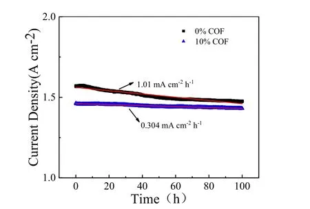
Fig. 2 Durability test at 0.2 V for the MEAs with and without the COF material in CL.
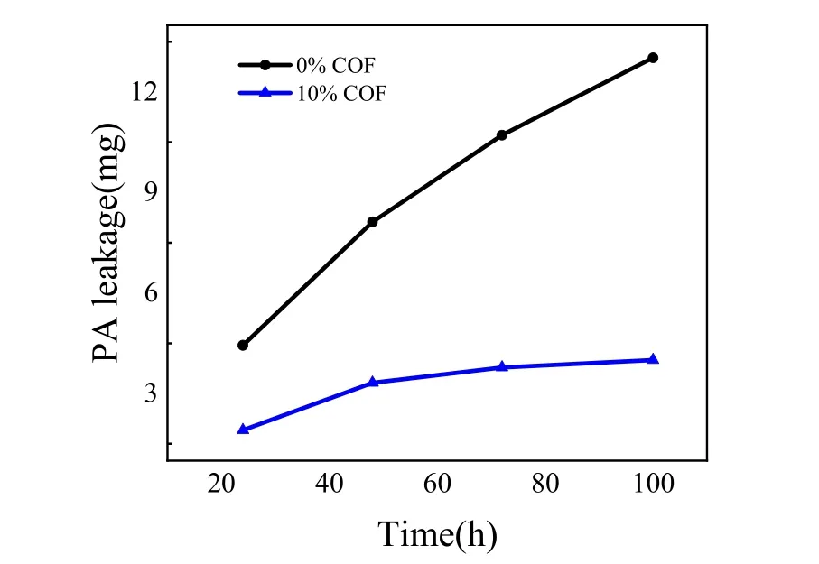
Fig. 3 The weight losses of phosphoric acid tested by ICP-AES.
3.3 Single cell performance and electrochemical characterization
To further understand the effect of the COF content on HTPEMFC performance, the MEAs containing 0-15% COF in the CLs were prepared and tested at normal operation conditions, as shown in Fig. 4. It is clear adding 5% and 10% COF in the CL did not impair the MEA performance, instead the performance was substantially improved in the region of normal operating voltage 0.4-0.7 V, which could be attributable to the improved proton transfer in CL due to the PA-loaded COF network that possesses superior proton conductivity21,22. However, excessive amount of COF could increase the gas transport resistance and electron transfer resistance in CL due to its inherent micropores(~0.46 nm) and electronic insulation properties. This should be the reason for the MEA containing 10% COF showing slightly reduced performance at high current densities (> 1 A·cm-2) and the one with 15% COF showing much inferior performance in both ohmic polarization and mass transfer polarization regions.To verify this point, the cell resistance of the MEA containing 15% COF in the CLs was measured by EIS, as shown in Fig. S3.The fitted ohmic resistance was near 0.2 Ω·cm2, ca. 40% higher than that for the MEA with 10% COF (see Table 1, shown latter),which was distinctly resulted from the increased COF content in the CLs. Based on these results, a proper COF amount of 5%-10% is suggested as the CL additive for the HT-PEMFC maintaining good durability and superior performance simultaneously.
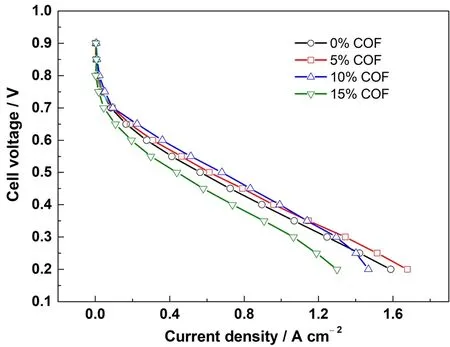
Fig. 4 Initial polarization curves of the MEAs with different amounts of COF in CL.
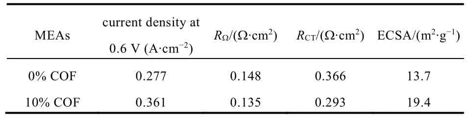
Table 1 Electrochemical properties of the MEAs.
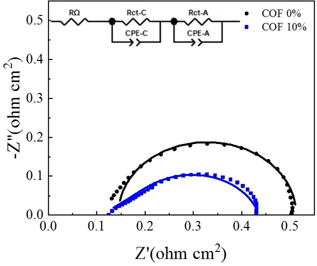
Fig. 5 In situ impedance curves of the MEAs with and without the COF material at 0.6 V.
To further explain the performance differences and validate the effect of the COF additive in CL, EIS and CV measurements were conducted. Fig. 5 presents thein situimpedance curves of the conventional MEA and the MEA containing 10% COF.Through simulation with ZView software, the corresponding ohmic resistance (RΩ) and charge transfer resistance (RCT) can be determined and summarized in Table 1. It can be seen that there is no significant difference in the ohmic resistances, which means a small amount of COF additive did not impair the electronic conductivity of the CL. On the contrary, the PA-loaded COF favors the protons transport in CL, so theRΩof the MEA containing 10% COF is even slightly lower than that of conventional MEA. Furthermore, theRCTof the MEA with 10%COF is much lower than that of the conventional MEA, implying that the COF-based CL possessed a more efficient electrochemical active layer where more reaction sites were created probably due to the interaction of PA impregnated COF network in the electrode. To prove this point, CV measurements are performed to study the ECSAs of the two MEAs, as shown in Fig. 6. The corresponding ECSAs are calculated from the H2desorption peak of each voltammogram and the results are also summarized in Table 1. The MEA with 10% COF in the CL shows higher ECSA comparing with the conventional MEA,probably due to its high specific surface area, good compatibility with PBI membrane, superior PA retention capacity and proton transfer ability that made more Pt surface available, thus leading to more TPBs in the CL. These electrochemical characterization(both EIS and CV) results are certainly consistent with theirI-Vperformances showed in Fig. 4, further validating the advantages of the COF material for HT-PEMFC application.

Fig. 6 Cyclic voltammograms of the MEAs with and without the COF material.
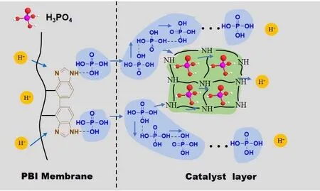
Fig. 7 Illustration the of PA retention and proton transfer mechanism of the COF
3.4 Mechanism analysis of performance and durability enhancement
Based on the above results, the mechanism for the performance and durability enhancement of the COF-based MEA is proposed and illustrated in Fig. 7. Similar to PBI polymer unit, the SNW-1 COF network possesses a large number of -NH- groups that are fine proton acceptors, which can well combine with H3PO4molecules that are proton donors.Furthermore, the well-defined porous structure of the SNW-1 COF can accommodate many “free” H3PO4molecules in CL,and most of these H3PO4molecules are immobilized in these cavities due to their similar size, thus the PA leakage during operation can be effectively reduced. Moreover, the H3PO4molecules inside the COF can also serve as efficient proton transfer sites due to the formation of dynamic hydrogen bond networks4. In this manner, the protons can be easily transferred in the COF-based CL because multiple pathways are created.Therefore, the COF additive in the CL simultaneously possesses proton transfer and PA retention abilities, consequently leading to the enhanced performance and durability of HT-PEMFC.
4 Conclusions
A novel strategy of introducing the SNW-1 COF material into CL was proposed in this work to reduce the loss of PA electrolyte during HT-PEMFC operation. The results from the ADT durability test and ICP-AES analysis confirm that the COF additive in CL can effectively decrease the PA leakage and then enhance the durability of HT-PEMFC, which are attributable to the superior PA retention capacity and the inherent proton transfer ability of the PA-loaded COF due to its well-defined porous structure and tailored functional groups (-NH-). The single cell test and electrochemical characterizations further reveal that a proper amount of COF (5%-10%) can also increase the performance of HT-PEMFC by decreasing the resistances and increasing the TPBs in the CL. Therefore, incorporating COF materials into CL could be a promising way to enhance the performance and durability of HT-PEMFCs based on PA-doped PBI membranes.
Supporting Information: available free of charge via the internet at http://www.whxb.pku.edu.cn.
