Recent Progress in Proton-Exchange Membrane Fuel Cells Based on Metal-Nitrogen-Carbon Catalysts
2021-09-28LiangDingTangTangJinSongHu
Liang Ding , Tang Tang , Jin-Song Hu ,*
1 Beijing National Laboratory for Molecular Sciences (BNLMS), CAS Key Laboratory of Molecular Nanostructure and Nanotechnology, Institute of Chemistry, Chinese Academy of Sciences (CAS), Beijing 100190, China.
2 University of Chinese Academy of Sciences, Beijing 100049, China.
Abstract: Proton-exchange membrane fuel cells (PEMFCs) directly transform chemical energy into electrical energy with high energy density and zero carbon emissions, thereby offering a clean energy alternative for fossil fuels and vehicle electrification. However, the existing PEMFCs rely on Pt-based catalysts, especially at the cathode side wherein the sluggish oxygen reduction reaction (ORR) takes place, resulting in high cost and limiting their commercial applications. Therefore,there is a strong interest in developing platinum group metal-free (PGM-free)PEMFCs. Although impressive advancements have been made since metalnitrogen-carbon (M-N-C) catalysts have been developed as promising candidates for low-cost cathode catalysts, PGM-free PEMFCs still suffer from insufficient activity and durability. Owing to the intricate structure of the tri-phase interface and mass transport limitation, the M-N-C catalysts with high ORR activity in rotating disk electrode (RDE) tests still suffer from unexpected problems such as showing low activity and undesired rapid degradation process in real fuel cell conditions. Therefore, a comprehensive understanding of the active sites and influences of the M-N-C catalyst structure and cathode structure on the PEMFC performance will promote the development of PGM-free PEMFCs. Herein, with an aim to increase the activity and durability of PEMFCs based on M-N-C catalysts, we summarize the recent progress in understanding the active sites of M-N-C catalysts and the relationships between the structures of catalysts/catalyst layers and device performances. At the catalyst level, multiple delicately designed synthetic strategies suggest that attractive device performances can be obtained by tailoring the intrinsic activity and density of the catalyst active sites while engineering the porosity of catalysts to improve the utilization of active sites. Additionally, integrating the catalyst ink into the cathode catalyst layers in PGM-free PEMFC is pivotal for transforming the impressive ORR performance of catalysts in the RDE test to fuel cell performance. Accordingly, the recent advances in the enhancement of mass transfer and charge transport to achieve remarkable fuel cell performance were also included by rationally designing ionomer contents, catalyst morphology, and fabrication process of cathodic catalyst layers. Moreover, durability is the Achilles heel of PEMFCs with M-N-C catalysts, which is currently far behind the commercial requirements. The possible degradation mechanisms and the recent progress in seeking the corresponding solutions are also discussed in this review, including the decomposition of metal species, protonation of nitrogen sites,corrosion of carbon support, and micropore flooding. Based on these insights, the perspective is proposed by articulating open challenges and opportunities in materials innovations and device engineering with an aim to achieve practical M-NC based PEMFCs.
Key Words: Proton-exchange membrane fuel cell; Platinum group metal-free catalyst; Metal-nitrogen-carbon;Oxygen reduction reaction; Electrolysis
1 Introduction
Fuel cells have emerged as one of the promising alternative technologies for vehicle electrification, featuring the distinctive advantages of efficient energy conversion, safety, and environmentally friendliness1-3. The direct transformation from chemical energy to electrical energy, which is not limited by the Carnot cycle, making the fuel cell devices inherit the merits of high efficiency and no harmful by-products. As listed in Table 14-7, fuel cells can be classified into the following types primarily by the kind of electrolyte: proton-exchange membrane fuel cells (PEMFC) with acid membrane electrolyte, phosphoric acid fuel cells (PAFC) with phosphoric acid electrolyte, molten carbonate fuel cells (MCFC) with molten salt electrolyte, solid oxide fuel cells (SOFC) with solid oxide electrolyte; alkaline fuel cell (AFC) with alkaline membrane electrolyte. Each of them has a specific application scenario. For example, the high operating temperature in SOFC and MCFC does not only propose severe restrictions on materials but also consumes several minutes to start up, which limited its application on the mobile device5. The AFC is sensitive to CO2, increasing the cost for removal of CO25.

Table 1 Comparison of different types of fuel cell and their fundamental information.
Among all types of fuel cells, PEMFC is one of the most promising techniques in the market. Thanks to the use of hydrogen as fuel, the PEMFC has distinctive advantages of low operation temperature, high energy density, non-emission of CO2, and short start-up time5,8. Therefore, PEMFC is suitable for application scenarios where portable, stable, and efficient energy is required. It is the first type of fuel cell used in massproduced fuel cell-powered vehicles due to its relatively low operating temperature and high power density9. Compared with the traditional thermal engine and lithium-ion batteries, the PEMFC has the advantages of high energy efficiency, high energy density, good reliability, low noise, and environmental friendliness, etc10.
The PEMFC device consists of the proton-exchange membrane (PEM), catalyst layer (CL), gas diffusion layer(GDL), current collector, and endplate11. PEM is the channel for proton transport. The catalyst layers are the regions where the oxygen reduction reaction (ORR) and hydrogen oxidation reaction (HOR) occur. The porous gas diffusion layer transports oxygen or hydrogen to electrodes and water to the outside.Generally, the PEM, CL, and GDL are the main components of the so-called membrane electrode assembly (MEA), which is commonly seen as the ‘heart’ of PEMFCs since the electric energy is mainly generated from the reactions happening there.Additionally, the current collector transports the generated current to the outer circuit. The endplates encapsulate and fix the whole fuel cell. The reactions in PEMFCs are shown below and schemed in Fig. 1.
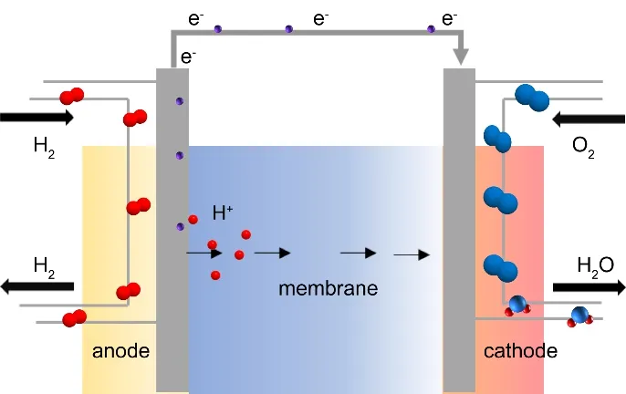
Fig. 1 Scheme for the operation process of PEMFCs.
Anode reaction: H2 → 2H++ 2e-
Cathode reaction: O2+ 4H++4e-→ 2H2O
Total reaction: 2H2+ O2→ 2H2O
During the operation, H2first adsorbed on the catalytic layerat the anode and then oxidized into adsorbed protons through HOR. The electrons are simultaneously released to external circuits and power the external load. The protons pass through the Nafion membrane and move towards the cathode. At the cathode, the oxygen molecules were reduced into H2O through ORR. There are two possible pathways for the ORR process as shown below. Both pathways involve multiple electron transfer and proton-coupled steps, causing sluggish kinetics and high overpotential.

Although PEMFC has good prospects of application in transport, energy storage, and industry, its commercialization is still suffering from high prices due to the use of platinum group metals (PGMs) as catalysts at both anode and cathode12,13. The PGM catalysts accounted for over 40% of the total cost in the fuel cell stack14. Additionally, compared with anodic HOR, the cathodic ORR still suffers from much lower kinetics, owing to the sluggish 4e-pathway. The cathode thus consumes the majority of total PGM catalysts, becoming the main limitation of fuel cell development15. Therefore, it is of significance and emergency to develop PGM-free catalysts prepared from earthabundant and inexpensive materials for ORR16-19. Besides,PGM-free catalysts have a high tolerance to impurities such as methanol, alcohol, ammonia, carbon oxides, which probably exist in hydrogen source and originate from the process of industrial hydrogen generation through steam reforming of ethanol, methanol, or natural gas20-23.
The PGM-free catalysts can date back to the 1960s when Jasinski24first reported that Co phthalocyanines exhibited ORR activity. In 2011, a zeolitic imidazolate framework (ZIF)-derived Fe-N-C catalyst synthesized by Dodelet’s group25showed an attractive power density of 0.75 W·cm-2at 0.6 V, which was comparable to PGM-based fuel cells. Inspired by these results,the researchers have embarked on studying PGM-free catalysts for PEMFC and achieved excellent ORR activity26-29. One of the most promising PGM-free catalysts is based on metalnitrogen-carbon (M-N-C) materials. Some of the PGM-free PEMFCs with M-N-C catalysts27,29-45have been listed in Table 2. Accordingly, a few descriptors of PGM-free PEMFC such as current density at 0.88 V (the Ohmic resistance is corrected) have achieved the 2018 goal of the US Department of Energy (DOE)in recent years. However, troubled by the heterogeneous structure, the genuine active sites in M-N-C catalysts remain arguable and it is still a lack of controllable synthetic approaches to prepare well-defined M-N-C structures with desirable active site density. The further enhancement of the catalyst activity and stability are needed but still of a great challenge46,47. Besides,other requirements such as for efficient mass transport and charge transfer should be also paid attention to the design of PGM-free catalysts.
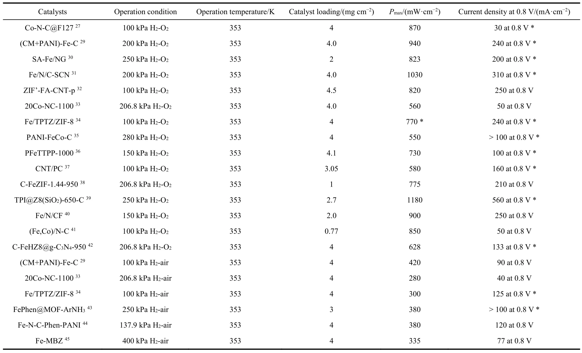
Table 2 Recent progress on PGM-free PEMFCs.
As shown in Fig. 248, during the operation, the cathode catalyst layer (CCL) involves various processes such as gas diffusion, H+transport, charge transfer, and H2O transport. Due to the poor volumetric activity of PGM-free catalysts, which is resulted from the low intrinsic activity and sparse active site density, the thickness of CCL in PGM-free fuel cell often reaches 100 μm25, 10 times thicker than that in PGM-based fuel cells (usually 10 μm)49. Such thick CCL in PGM-free fuel cells leads to evident resistance for oxygen transport and ohmic resistance for charge transfer. Enhancing the intrinsic catalytic activity, creating more active sites, as well as introducing suitable porosity structure in CCL are effective to enhance the device performance. Sunet al.31reported that the electronicmodification of the M-N-C catalystviaS doping resulted in better intrinsic activity and thus an outstanding cell power density of 1.03 W·cm-2. Liu’s group36obtained an M-N-C catalyst with a high density of active sites using a porous organic polymer as the precursor, enabling an enhanced PGM-free PEMFC performance with a peak power density of 0.73 W·cm-2.Atanassovet al.50systematically investigated three kinds of Fe-N-C catalysts with various porosity structures, concluding that the pore connectivity could be a proper descriptor to fuel cell performance.
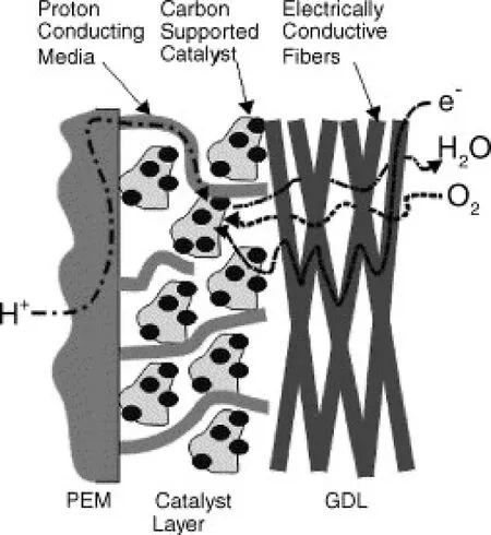
Fig. 2 Scheme for the cathode catalyst layer.

Fig. 3 The performance comparison of state-of-the-art PGM-free PEMFCs and DOE 2025 targets.
For the transport application, more importantly, the durability of PGM-free PEMFC is another decisive criterion51,52.However, the stability of state-of-the-art M-N-C PEMFC is far below than PGM PEMFC. Based on the published results, four primary degradation mechanisms have been proposed: (1)decomposition of metal species (which could be destroyed by physical or chemical processes in a fuel cell); (2) protonation of active N species (which may combine with proton and lose activity in an acidic environment); (3) corrosion of carbon support (which suffers from the attack of electron or chemical reagents like H2O2); (4) micropore flooding during operation. It is necessary to note that all pathways may contribute to the degradation to a varying extent depending on the compositions and structures of catalysts. The complex interaction among these mechanisms brings difficulties in uncovering the reasons for activity-loss and developing specific solutions.
Fig. 3 summarizes the performance comparison between the 2025 targets set by DOE and the current achievements of PGM-free PEMFCs. It is clearly seen that there are still huge gaps in both activity and stability53, calling for great efforts on the development of highly active and stable PGM-free catalysts at the device level. This review will discuss the main challenges and recent progress of PEMFC prepared by M-N-C catalysts. In view that the anode and membrane for current M-N-C PEMFCs are approaching the commercial requirements, the review will mainly focus on the issues and solutions in the activity and durability on the cathode. We introduce the progress of the cathode of M-N-C PEMFC on the designing of active sites, the porous catalyst structure, the optimization of catalyst layers, and the degradation mechanisms. All these factors make cooperation to obtain an outstanding performance of M-N-C PEMFC (Fig.4).
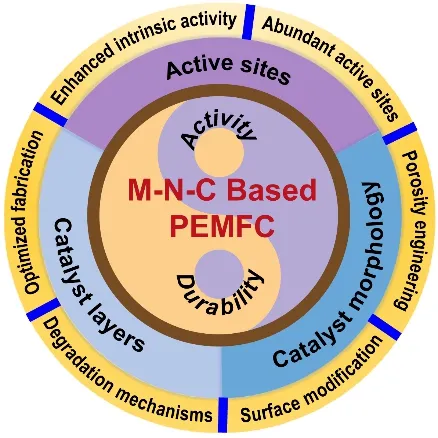
Fig. 4 Scheme for the M-N-C based FEMFC designing targets for large-scale applications.
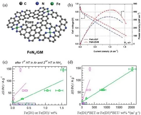
Fig. 5 (a) Scheme for pore-edge Fe―N4 sites model; (b) PEMFC performance in H2-air condition The peak power density was 0.43 W·cm-2;(c, d) correlation between the mass activity and Fe (D1) or Fe (D3) contents without (c) or with (d) correction of surface area.
2 Activity improvement of M-N-C based PEMFCs
As mentioned above, the cathodic ORR in PEMFC is sluggish. The state-of-the-art catalysts for PEMFC are based on Pt group metal, whose costly price and low abundance hinder the scale-up of PEMFC. M-N-C is a promising alternative to PGM-based catalyst in view of the relatively high ORR activity.Nevertheless, the PEMFCs with M-N-C catalysts still show insufficient activity and stability compared with PGM-based catalysts54,55. To promote the performance of PGM-free PEMFC, the rational design of the cathode catalyst layer containing highly active and stable catalysts for ORR and proper porous structure for efficient mass transfer is needed. In this section, the approaches to enhance the activity of M-N-C catalysts and thus to the PEMFC performance will be firstly discussed, followed by the rational design of the porous structure to promote mass transfer as well as the optimization of cathode catalyst layer towards high-performance devices.
2.1 Engineering of accessible active sites
Although the exact ORR active sites in M-N-C catalysts are still in the debate in view of the complicated structures and multiple candidates such as M―Nx, metal carbide, metal nitride,CNx, etc., M―N4has been commonly acknowledged as the main active sites29,56. Some reports proposed that the activity and local structure of M―N4 depended on its position on a carbon support, coordination environment, and heteroatoms, offering the possibilities to tune the performance of PEMFC46,57-59. Chen et al.28used NH4Cl during the catalyst preparation to generate abundant pores and nitrogen-doped edges for hosting Fe―N4active sites (Fig. 5a). DFT results confirmed that such pore-edge configuration modified the intrinsic activity of Fe-N4. Based on such a catalyst, the PEMFC with a peak power density of 0.43 W·cm-2in the H2-air condition was demonstrated (Fig. 5b).Besides the designing of the single-atom site, Xing et al.60developed a Fe-Co dual atom site. By optimizing the absorption energy of ORR intermediates, the PEMFC derived from this catalyst exhibits an impressive maximum power density of 0.873 W·cm-2. Thanks to the development of advanced spectroscopic techniques such as X-ray absorption spectra (XAS) including X-ray absorption near edge structure (XANES) and extended X-ray absorption fine structure (EXAFS), electron energy loss spectroscopy (EELS), Mössbauer spectroscopy, etc., the fine structure of Fe―Nxcould be identified. Using the Mössbauer spectra, Dodelet’s group61built up the dependence of fuel cell performance and Fe―N4structure. In their previous work, it was found that the D1, D2, D3 in the Mössbauer spectrum were related to Fe―N4, Fe―N2+2, N―Fe―N2+2, respectively. The difference of dz2in various Fe―Nxdetermined their binding strength with an oxygen molecule and thus the ORR activity.The Fe―N4and N―Fe―N2+2with unfilled dz2orbits were disclosed to be more active for ORR. Subsequently, they deduced the linear relationship between the content of Fe (D1)and Fe (D3) in catalysts and the mass activity of PEMFC at 0.8 V62. As illustrated in Fig. 5c, there was a positive correlation between Fe moiety [Fe (D1) or Fe (D3)] and the performance of PEMFC. Moreover, after the correction by multiplying BET surface area and Fe contents, the relative errors were significantly improved (Fig. 5d), indicating that the Fe active sites located at the surface contributed more to PEMFC performance. This implied that increasing the density of surfaceactive site could improve the activity of PEMFC.
In 2006, by varying the heat-treating time to tune the porous structure of catalysts, Dodelet et al.63suggested that the micropores could accommodate the active sites and the ORR activity of catalysts was closely related to the surface area of micropores. However, the activity of Fe-N-C catalysts prepared on porous carbon black with high BET surface area didn’t show higher activity than those on normal carbon support64. A hypothesis has been proposed that NH3could not directly transform into surface nitrogen to form Fe―N4 active sites because there were too few disordered carbon species in carbon support to react with NH3. To increase the density of surface Fe―N4active sites, planetary ball-milling was creatively used to fill the micropores with the mixture of pore fillings and iron precursors by the same group. After pyrolysis under the NH3atmosphere, more surface catalytic sites together with the suitable porous structure were obtained in carbon support (Fig.6a). After the Ohmic resistance is corrected, an impressive volumetric current density of 99 A·cm-3at 0.8 V was then achieved. Unfortunately, looking at the polarization curves (Fig.6b), it is clear that the PEMFC performance is still poor in the mass limited region. This indicates that only modifying the catalyst structure and/or the density of active sites is not enough for PGM-free PEMFC to obtain similar performance to PGM-based fuel cells.
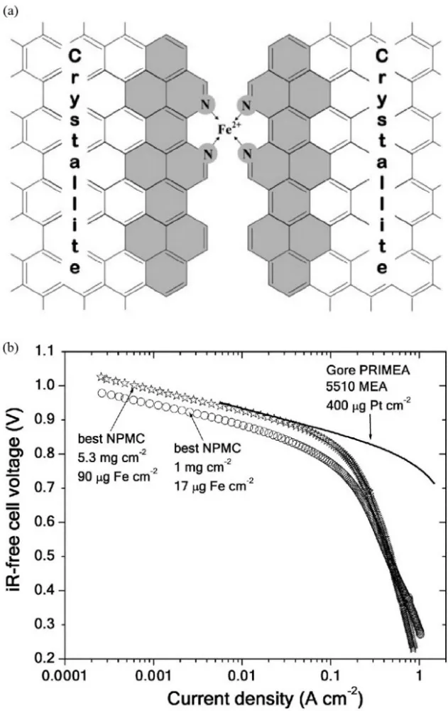
Fig. 6 (a) Schematic model of the presumed active site between two carbon crystallites after pyrosis; (b) performance comparison of the PGM-free catalyst with PGM catalyst in H2-O2 PEMFC test.
Another novel two-step strategy to increase the density of active sites was proposed by Wu et al.26. In a typical synthesis process, Mn was first doped in ZIF-8 to form a precursor and then the Mn-doped porous carbon support was obtained after carbonization and acid leaching. Subsequently, additional Mn source and cyanamide were adsorbed in the derived porous carbon. The final catalyst after thermal activation exhibited superior activity with a power density of 0.46 W·cm-2in a fuel cell test. The formation of Mn aggregates which readily occur due to a wide Mn valence change from 0 to +7 was avoided through such a synthesis process. High mass content of Mn of 3.3% was detected by ICP-MS and the aberration-corrected MAADF-STEM further confirmed the atomically dispersed MnN4sites.
Although there are plenty of synthetic approaches have been developed to improve the loading of metal sites65-68, some of the M-N-C active sites are inevitably buried in the carbon matrix and cannot take part in catalytic reactions. Shui et al.39reported an effective strategy to prepare porous concave-shaped M-N-C catalysts to improve the utilization of active sites, as shown in Fig. 7a. SiO2beads were used to coat ZIF-8 dodecahedron. After preheating and etching out SiO2 templates, negative zeta potential ζ was generated inside the ZIF-8, enlarging the micropore size. Therefore, the TPI ions ([Fe(Phen)3]2+, Fe(Ⅱ)-phenanthroline complex) could be absorbed and encapsulated inside the ZIF-8 via electrostatic interaction. Moreover, the concave shape and numerous mesopores on its surface gave the larger exterior surface, exposing more active sites and facilitating mass transport (Fig. 7b, c). With this strategy, metal utilization was improved to ~43%. As a result, the current density at an iR-corrected potential of 0.88 V in the PEMFC test under 100 kPa H2-O2reached 0.047 A·cm-2, matching the DOE targets in 2018 (Fig. 7d).
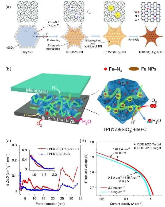
Fig. 7 (a) Synthetic process of TPI@Z8(SiO2)-650-C; (b) schematic illustration of active sites on TPB in TPI@Z8(SiO2)-650-C; (c) comparison of pore size distributions in TPI@Z8(SiO2)-650-C and TPI@Z8-650-C; (d) polarization curves of H2-O2 fuel cells with TPI@Z8(SiO2)-650-C in different loadings, showing the current density at 0.9 V and the volumetric activity at 0.8 V (the Ohmic has been corrected).
2.2 Engineering of mass transfer properties
The reaction conditions in fuel cell operation are significantly different from the ideal conditions in tests on the rotating disk electrode (RDE). The device performance is appreciably affected by the issues of mass transport and water flooding. To diminish these effects, it is of vital importance to construct triphase interfaces for enhancing the accessibility of gas and electrolyte to active sites. One of the prominent factors affecting the tri-phase interfaces is the pore size. All three types of pores in various size ranges contribute to the operation of fuel cells.Most active sites sit in the micropores (1-2 nm). The mesopores(2-50 nm) benefit the accessibility of gas or proton to the active sites. The macropores facilitate the mass transport of reactants and products69. Therefore, much effort on boosting the performance of PGM-free cathode has focused on designing hierarchical pore structures in M-N-C catalysts with micro-,meso-, and macropores inside.
The nitrogen-containing carbonaceous precursors have been commonly used to create highly active M-N-C sites while achieving porous structures in numerous literature70,71. In 2017,Zelenay et al.29have reported that multiple nitrogen precursors had the potential to create hierarchical porous morphologies in M-N-C catalysts. They combined polyaniline (PANI) and cyanamide (CM) to prepare the catalysts. Compared with previous work, the introduction of cyanamide generated more gaseous species during the pyrolysis to form more meso/micropores in the catalysts. The SEM images clearly showed the morphology differences between (CM+PANI)-Fe-C and PANI-Fe-C (Fig. 8a, b). The BET results indicated that both surface area and pore volume of (CM+PANI)-Fe-C were notably larger than PANI-Fe-C (Fig. 8c). The more opener framework allowed the uniform distribution of the ionomers, improving the tri-phase interface and mass transfer. The MEA with such (CM+PANI)-Fe-C catalyst produced a peak power of 0.39 W·cm-2under H2-air at 100 kPa pressure (Fig. 8d).
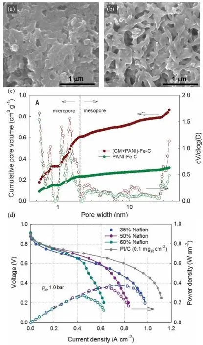
Fig. 8 (a, b) SEM images and (c) pore size distribution and pore volume of PANI-Fe-C and (CM+PANI)-Fe-C; (d) polarization and power density curves of MEAs prepared by Pt/C and (CM + PANI)-Fe-C with different Nafion contents.
Since the porous structure plays an important role in performance improvement, the metal-organic frameworks(MOF) with nanoporous structure has been widely used as the good precursors with uniform distribution of selected metal,carbon, and nitrogen and porous to prepare M-N-C catalysts72.For example, Zn-containing MOFs are commonly used to deliver high-performance catalysts33,38. Sun’s group38used ZIF-8 to trap the vaporized ferrocene and obtained a porous MN-C catalyst after pyrolysis. As shown in SEM images (Fig. 9a,b), with the incorporation of ferrocene, the catalyst holds a similar morphology but a more porous structure. When the mass ratio of ferrocene was 1.44, the catalyst exhibited the best electrocatalytic activity (Fig. 9c). The H2-air fuel cell with this catalyst exhibited a power density of 0.463 W·cm-2(Fig. 9d),better than most of the PGM-free cathodes. The performance improvement could be attributed to the following reasons: 1) the abundant micropores in ZIF-derived catalysts could host more active sites; 2) the high nitrogen content in ZIF precursor enabled to form more Fe―N4active sites; 3) the uniform distribution of each constituent was beneficial to form the uniform and densely distributed Fe―N4sites, giving more accessible active sites; 4) the evaporation of Zn species under the pyrosis process resulted in a hollow structure for exposing more active sites and facilitating mass transport. Additionally, the ZIFs can also transform to carbon support with high surface area and nitrogen content to prepare M-N-C catalysts for ORR. For example, Mu et al.73successfully obtained Co-N-C nanorod array frameworks transformed from ZIF nanocrystals which exhibited a large surface area to expose active sites and mesopore structure to enhance mass transports. As a result, high activity and durability of the catalyst were observed in the ORR test, opening a new insight toward ZIF-derived carbon support for fuel cell application.
To facilitate the mass transfer, the macroporous channel could be designed to make more actives sites freely accessible to the reactants while constructing densely distributed micropores to expose more surface-active sites in the catalyst74. Liu et al.40have reported such a structure through electrospinning methods.In a typical synthesis, the polymer solution was mixed with ZIF-8 and tris-1,10-phenanthroline iron (II) perchlorate (TPI)solution as the precursor. After the thermal treatment, the catalyst showed both macropores and micropores while keeping the morphology of electrospun nanofibers, as shown in Fig. 10a,b. The micropores densely dispersed inside the nanofibers due to the thermal decomposition of polymer precursor, while there are a considerable amount of macropores from the interspaces among nanofibers, which could improve the mass transfer process during the operation of fuel cells. As a result, an impressive volumetric activity of 450 A·cm-3was achieved under the standard testing condition for fuel cells made by the DOE. Its peak power (0.9 W·cm-2) was significantly higher than the control cell assembled by the catalyst with Ketjenblack support (Fig. 10c). A similar strategy has been adopted by Wu’s group75recently. They prepared Co-N-C catalysts with macropores and micropores by co-electrospinning the mixture of cobalt-doped ZIFs, polyacrylonitrile (PAN), and poly(vinylpyrrolidone) (PVP). Compared with the catalysts obtained through direct pyrolysis of Zn/Co-ZIFs nanoparticles, such catalyst exhibited higher ORR activity in fuel cell tests under H2-air condition. The systematic study proved that several factors including the selection of polymer, metal ratio, and heat treatment were of importance to tune the porosity and morphology of catalyst for enhancing the mass transfer.Additionally, they observed that the uniform distribution of ionomers in the catalyst layer was vital to improve the MEA performance, which would also be discussed in the later section.
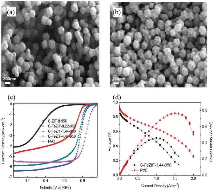
Fig. 9 (a, b) SEM images of C-ZIF-8-950 (a) and C-FeZIF-1.44-950 (b); (c) LSV curves at 0.1 mol·L-1 HClO4; (d) polarization and power density curves of MEAs prepared with C-FeZIF-1.44-950 and Pt/C in H2-air PEMFC tests.
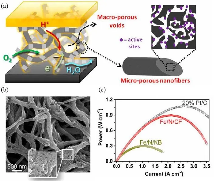
Fig. 10 (a) Schematic illustration of macropores for mass transfer and micropores for hosting active sites; (b) SEM images;(c) power density curves, measured in PEMFC test at 200 kPa H2-O2 condition.
2.3 Optimization of the cathode catalyst layer
It should be noted that only those exposed active sites accessible to proton and oxygen can effectively catalyze the O RR. Reactants such as oxygen or proton diffuse through the CCL to reach the active sites on the tri-phase interface. Therefore,besides the optimization of catalysts, the structure of CCL should also be optimized since it closely affects the cathode performance. The CCL in PGM-free fuel cell is usually much thicker than that in PGM-based fuel cells because the volumetric activity of the PGM-free catalyst is significantly lower than PGM catalyst14. The thicker CCL brings resistance and issues to transfer gas and ions, calling for the suitable design of CCL for PGM-free fuel cells76.
2.3.1 Effect of ionomer content
Generally, the CCL consists of the catalyst layer and porous gas diffusion layer, which were encapsulated in the ionomers.The ionomers affect the proton transport and ohmic resistance of CCL. The high content of ionomers is beneficial to the charge transfer while increasing the diffusion resistance of oxygen. The fewer ionomers will delay the proton transfer while the excessive ionomers will separate the catalyst nanoparticles and block the electronic pathway77. Zelenay et al.78investigated the effect of ionomer content on the performance of fuel cells. The MEA was prepared by a hot-pressing method with various mass contents of ionomer ranging from 25 % to 55 %. The SEM image of MEA(Fig. 11a) showed that the PGM-free catalyst layer was much thicker than the Pt catalyst layer. The polarization curves in Fig.11b indicated that the CCL with the mass fraction of Nafion ranging from 35% to 55% was more active in the kinetic region compared with that with 25% Nafion whereas the higher contents of ionomers caused water flooding and mass transfer issues. As a result, the optimal mass content range was 35 % to 45% in their experiments. Malko et al.79developed a delicate method based on EIS measurement to better evaluate the suitable content of ionomer. It was found that a 45° line would be shown in the high-frequency region in the impedance spectrum if the ionomer content was proper. Subsequently, Ye et al.80found a critical ionic conductance value of 100 S. When the ionic conductance was below 100 S the resistance of fuel cell was dominated by proton conductivity. Otherwise, it would be dominated by other factors such as mass transfer if the conductance was over 100 S (Fig. 11c). Based on this understanding, they fabricated a large MEA (50 cm2) with an outstanding power density of 0.57 W·cm-2at the H2-air condition (Fig 11d). These results suggest that the rational design of CCL with a proper amount of ionomers can improve cell performance81.
2.3.2 Effect of catalyst morphology
To achieve fast proton and electron transport while keeping efficient mass transfer, the CCL requires ionomer uniformly infiltrating catalyst particles and leaving spaces for reactants to pass through. The interaction between catalyst particles and ionomer will affect the CCL performance82.
Lister’s group83systematically investigated the effect of catalyst particle size on this interaction. Fe-N-C catalysts with various particle sizes were used to prepare MEAs. The ionomer distribution in these MEAs was characterized by the nano-CT technique. As depicted in Fig. 12a, it was difficult for the ionomers to infiltrate the small catalyst particles since the gap was too narrow. What’s worse, the small particle tended to aggregate (Fig. 12b) and stop ionomers infiltrating. While the too large particles stacked thick ionomer films, leading to mass loss or water flooding. Other factors affecting MEA performance like resistance was also evaluated. The EIS (Fig. 12c) results suggested that the large particles (600 nm) were unfavorable for proton transfer in terms of low conductivity of 0.6 S·m-1while the small particles (100 nm) showed a better conductivity of 2 S·m-1. Such values of conductivity were affected by the reasons following: (1) the water provided a path between ionomer branches to transfer proton; (2) the large particles (600 nm)caused a long distance between the ionomer branches, increasing the resistance coming from water.
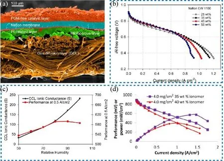
Fig. 11 (a) SEM images of MEA with GDL and catalyst layers; (b) iR-free polarization curves measured in H2-air fuel cells for the MEAs with various amounts of ionomers; (c) plots of CCL ionic conductance (black line) and cell performance (red line) as a function of relative humidity;(d) power density curves of fuel cells with various amounts of ionomers in H2-air.
Comprehensive effect based on those factors above, the catalysts in 60 and 80 nm may exhibit superior ORR activity(Fig. 12d, e) but they were liable to form aggregates in random size and the results were not reproducible, limiting their applications. The best and repeatable MEA performance was achieved on the catalyst with a particle size of 100 nm. As depicted in Fig. 12f, the MEA demonstrated a current density of 28.5 mA·cm-2at 0.9 V after high-frequency resistance (HFR)was subtracted from the Nyquist plot under 100 kPa O2,exceeding most of the PGM-free fuel cells in the same conditions.

Fig. 13 (a) Morphologies of three kinds of CCLs; (b) current density curves with water saturation for CCM, GDE-CCM,GDE, GDE(E).
Moreover, there are several examples of the effect of different catalyst morphology on PEMFC performance39,44. Chen et al.44reported an architecture with 2D graphene sheets self-assemble on the 3D porous carbon support by introducing phenanthroline(Phen) and polyaniline (PANI) as two kinds of nitrogen sources.The Phen was a pore-forming agent to construct a 3D framework and PANI would transform into graphene during pyrosis. The Fe-N-C catalyst prepared with Phen and PANI exhibited both merits of the catalysts obtained through a single N source. In detail, the porous structure facilitated the mass transfer during the fuel test and the graphene-like sheets on the framework enhanced the electron transfer and corrosion resistance of catalyst. Therefore, the Fe-N-C-Phen-PANI showed a higher fuel cell performance than Fe-N-C-Phen and Fe-N-C-PAN.However, there is no specific characterization about the distribution of ionomer and we suppose that there may be stronger interaction between the Fe-N-C-Phen-PANI catalysts and ionomers than the other two catalysts derived from a single N source. A deeper study to explore the cathode layer in the future may be helpful.
2.3.3 Effect of fabrication methods of CCL
The fabrication methods have also a critical impact on the performance of CCL. Atanassov’s group84investigated the effect of three kinds of CCLs (marked as CCM, GDE-CCM, and GDE) on the performance of PGM-free PEMFC. The difference among these CCLs was the deposition procedures of the catalysts. For CCM, the catalysts were deposited on the membrane, followed by hot-pressing onto the GDL. For GDE,the catalysts were deposited on the micropores layer (MPL) of GDL and then hot-pressed onto the membrane. For GDE-CCM,the catalysts were deposited on both MPL and membrane before hot-pressing.
As displayed in Fig. 13a, there were porous structures at the interfaces of CL/MPL, CL/PEM, and in the middle of CL for CCM, GDE, GDE-CCM, respectively. Due to the used electrocatalysts were hydrophobic, the water mainly wetted the pore structure, as confirmed by operando X-ray CT. The water flooding was competitive with oxygen diffusion. As a result,these CCLs presented different behaviors under various water saturation levels. Under low water saturation, the oxygen concentration was sufficient for ORR and the current density was thus limited by proton transfer. CCM had the most favorable ionic conductivity because its CL was close to the membrane.On the contrary, at the high water saturation, oxygen would be severely blocked by water flooding. Therefore, the GDE where CL could contact more oxygen exhibited the highest current density among those samples. For an intermediate level of water saturation, the current density was related to both oxygen and ions concentration. GDE-CCM thus showed a higher current density because it could provide sufficient oxygen and proton.These results concluded that the fabrication process of CCL appreciably influenced its performance. Consequently, the author came up with a structure of GDE(E) where a Nafion layer was placed between the membrane and GDE. Such a structure delivered high ionic conductivity and thus improved fuel cell performance (Fig. 13b). Similarly, other parameters such as the ionomer chemical property78, ink compositions85, drying methods86, etc. have also been studied and shown their effects on the cell performance.
3 Durability improvement of M-N-C based PEMFCs
During the past decades, the activity of the PGM-free electrocatalyst for cathode has made significant progress33,35,38,39.However, there are still overwhelming gaps between scientific research and commercial application. One is the poor durability of the cathode. For most applications, the operation time of fuel cell is required for over 5000 h, which is much far away from the state-of-the-art PGM-free fuel cells (commonly hundreds of hours)76. In 2011, Wu et al.35reported a PANI-derived PGM-free catalyst, which enables an H2-air fuel cell to run stably at 0.4 V for 700 h with a current density of about 0.3-0.4 A·cm-2.Unfortunately, such durability is still far below the DOE’s target of 8000 h start-up/shut-down cycles and its efficiency was still insufficient. Generally speaking, non-precious metal and carbon are thermodynamically unstable in acid environments. As a result, the activity of the M-N-C cathodic catalyst usually decreased by 40%-80% during the first 100 h87. Although the complete degradation mechanisms are still not fully understood,there are probably four mechanisms responsible for the performance degradation of PGM-free cathodes: (1) the decomposition and loss of metal species; (2) the protonation of nitrogen active sites with or without the following anion adsorption; (3) the corrosion of carbon support; (4) the micropores flooding in catalyst layers. It is worth noting that these degradation mechanisms may work simultaneously during the operation of fuel cells. For example, the corrosion of the carbon support or the micropore flooding may cause the decomposition and loss of metal species while the metal ions will accelerate the corrosion of carbon support or membrane88.These complex interactions increase the difficulty in understanding the undergoing degradation mechanism. In this section, a few examples of these issues, and possible solutions in recent literature will be discussed.
3.1 The decomposition of metal species
It is generally considered that metal species contribute to the activity of PGM-free catalysts56,89,90. The decomposition and loss of metal species will cause the degradation of PEMFC performance. Some reports have observed the demetallation of Fe in the Fe-N-C catalyst during the operation of the fuel cell.Baranton et al.91reported that the Fe species could be substituted by proton and lost activity. Dodelet’s group88found a positive correlation between the current decay and the loss of Fe sites during the fuel cell test. According to the principle of thermodynamic equilibrium, they thought Fe―N4was thermodynamically unstable in the system. Once the Fe species detached from the active sites, the humidified gas stream would flush them away, making Fe ions and Fe―N4 could not reach Le Chatelier equilibrium.
To understand the metal leaching process, Choi’s group92synthesized three kinds of Fe-N-C catalysts with a various composition (Fig. 14a-c): FeNC-wet-1 with active FeNxCymoieties and inactive Fe particles; FeNC-dry-1 with similar FeNxCy but less amount of inactive Fe particles; FeNC-dry-0.5 with similar FeNxCyand undetectable Fe particles. The operando SFC/ICP-MS was used to monitor the Fe concentration during the entire reaction. The insoluble Fe(III) particle had accessibility to become Fe(II) ions, as a result of the redox potential of Fe(III) and Fe(II) was 0.77 V vs. RHE at low pH. As expected, for the FeNC-wet-1, considerable Fe leached (about 705 μg Fe for every gram catalyst) during the first 20 CV recycles at a potential below 0.7 V vs. RHE. For FeNC-dry-0.5,the leached Fe was detected with a value of 10 μg Fe for every gram catalyst, which indicated the stability of Fe―NxCy moieties. As a result, to minimize the effect of Fe leaching in Fe-N-C catalysts, they designed effective methods to remove the inactive Fe particles by using electrochemical CV reduction and chemical reduction by SnCl2/HCl solution.
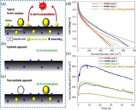
Fig. 14 (a, b, c) Schematic illustration of various catalysts; (d) polarization curves at H2-O2 condition. Solid line: initial curves;dashed line: after first 50 h test; (e) current density curves in the stability tests at H2-O2 condition.
However, no appreciable durability improvement was observed for the post-treated catalysts during the first 50 h fuel cell tests in their experiments and their decay curves were in parallel (Fig. 14d-e). As a result, the authors proposed that the degradation may be caused by other species such as the H2O2,the by-product during fuel cell operation. The leaching Fe species may catalyze the decomposition of H2O2and the formation of reactive oxygen species (ROS) by Fenton reaction and accelerate the corrosion of carbon support, which causes the decay of the fuel cell. Although the exact degradation mechanism caused by the decomposition of metal species is in debate, synthesizing M-N-C catalysts with exclusive M―N4active sites and without inactive metal species has been proved as an effective way to mitigating demetallation and moderate the depreciated performance of the PGM-free cathode89.
3.2 Protonation of nitrogen sites
The protonation of active sites was proposed as one of the possible degradation mechanisms in 2009 by Popov’s group93.As depicted in Fig. 15a, the pyridinic N with the lone pair of electrons could not delocalize and thus readily adsorb the proton in acid solution. Once it was protonated, it would not offer a lone pair of the electron to promote reactive oxygen adsorption.Based on this hypothesis, the author rationalized why the catalyst NMCC-1100 prepared at 1100 °C was more stable than NMCC-800 prepared at 800 °C in the H2-air test (Fig. 15b). The NMCC-800 had both pyridinic N and quaternary N while only quaternary N existed in NMCC-1100 (Fig. 15c). Although both the pyridinic and quaternary N were active toward ORR, the protonation of pyridinic-N in NMCC-800 in an acidic environment would lose activity while the quaternary-N would not. Later on, Banham et al.51pointed that if this hypothesis was correct, the more rapid proton transfer in the RDE test would result in the similar performance of NMCC-800 and NMCC-1100, which was not observed by Popov et al. The anion-binding effect following the protonation of N sites was then proposed by Mukerjee’s group94. As shown in Fig. 15d, the neighboring N had accessibility to tune the turnover frequency (TOF) of Fe―N4. If it was protonated to NH+, the Fe―N4…NH+remained highly active to ORR. However, if the NH+formed NH+A-(A = anions, could be the sulfonate anions.), the TOF would be very low. According to their report, this anion binding effect was reversible, the activity decay could be recovered by chemical or heat treatment. If this hypothesis is reliable, it would enable us to imitate a successful example to avoid such an anionbinding effect using some molecules to occupy the unnecessary sites while leaving sufficient metal sites to adsorb and catalyze oxygen reduction95. However, relevant reports about anion absorb effect are still uncommon and more efforts are needed to step the way for the application of PGM-free PEMFC.
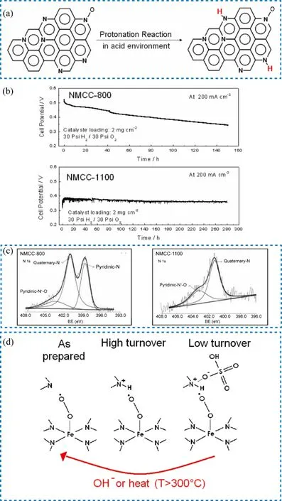
Fig. 15 (a) Schematic illustration of the protonation process; (b) current density changes in stability test at H2-air condition;(c) comparison of N 1s XPS spectra of NMCC-800 and NMCC-1000; (d) schematic illustration of anion-binding effects.
3.3 The corrosion of the carbon support
Carbon support acts as not only the host of active sites but also a n electron conductor for M-N-C catalysts. Its corrosion will cause the loss of active sites and harm electron transport, thus degrading the performance of the cathode (Fig. 16a)81,96.Unfortunately, the corrosion is inevitable since the oxidation potential of 0.207 V vs. RHE for carbon oxidized to carbon dioxide is far below the operation potential of the fuel cell97.Sun’s group98observed the existence of an oxygen-containing carbon functional group at the potential below 0.9 V vs. RHE.Choi et al.99reported that CO2was detected when the potential went to 0.9 V vs. RHE or higher. It should be noted that besides the electrochemical oxidation, the carbon support also bears chemical oxidation from H2O2and ROS81,100,101. H2O2is one of the common by-products of the partial reduction of oxygen in fuel cells. The demetallation of Fe will accelerate the generation of H2O2via Fenton reaction, which is one of the reasons for more H2O2or ROS in the PGM-free system than in PGM fuel cell.Choi et al.99found that CO2could be detected at 0.3 V vs. RHE in the H2-O2fuel cell test, which was attributed to the chemical oxidation. The mechanism for the corrosion of carbon support due to H2O2was further investigated. Jaouen et al.101revealed the H2O2would decrease the TOF of catalysts by oxidizing the carbon surface in acidic media but not in an alkaline environment. This implied that the corrosion might come from the attack of ROS generated from H2O2rather than molecular H2O2itself.
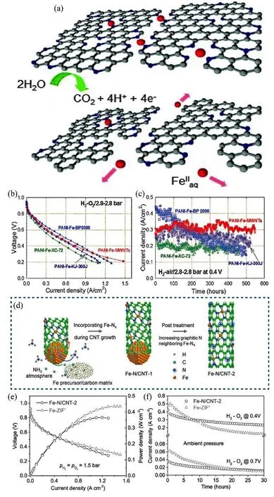
Fig. 16 (a) Schematic illustration of the carbon corrosion; (b) polarization curve in H2-air fuel cell with the catalysts on different carbon supports;(c) current density curves of various catalysts in 500 h stability test in H2-air fuel cell; (d) schematic illustration of the growth process of Fe-N-CNT-2;(e) polarization and power density curve, and (f) current density curves in the stability test for Fe-N-CNT-2 and Fe-ZIF in H2-O2 fuel cell test.
To minimize the effect of carbon oxidation, two strategies have been considered in the recent literature: 1) enhancing the anti-corrosion of the carbon support; 2) decreasing the generation of H2O2or ROS. Zelenay et al.102believed that improving the degree of graphitization was an effective way to relieve carbon corrosion. To support this conclusion, they introduced multi-walled carbon nanotubes (MWCTs) as the support to synthesize Fe-N-C catalysts. Compared to ordinary carbon support, the MWCTs had a higher degree of graphitization, which could not only promote the electron transfer but also enhance the stability. The stability test showed that the PANI-Fe-MWNT catalyst maintained a stable current density for 500 h at 0.4 V (Fig. 16c). A similar catalyst (Fe-N/CNT-2) was reported by Kang et al.103, they used Fe to catalyze the growth of carbon nanotubes under the NH3atmosphere while Fe atoms would simultaneously dope on the walls of CNTs. The scheme of catalyst growth is illustrated in Fig. 16d. This catalyst showed higher stability than the ZIF-derived Fe-N-C catalyst (Fig. 16f), which was ascribed to a higher degree of graphitization. However, the polarization curves of the treated catalysts mentioned above decreased slightly (Fig. 16b, e). This could be due to that the low defect density on carbon support from increased graphitization accommodated the less active sites. Therefore, the activity and stability have to be balanced during the modulation of the graphitization of support.
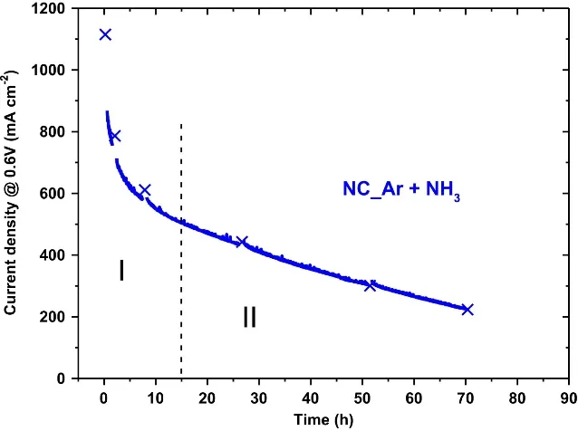
Fig. 17 Chronoamperometry curve showing the degradation behaviors of PGM-free PEMFC.
Another strategy is to limit the production of H2O2or ROS to prevent carbon support from chemical attacks. It has been proved that improving the 4e-pathway selectivity of ORR catalysts was effective to minimize the H2O2generation104.Selecting additives for PGM-free catalysts such as CeO2to consume hydrogen peroxide is another alternative way to enhance stability performance. Zou’s group105incorporated CeO2 in the catalyst to significantly reduce the production of H2O2, saving a 50% loss of E1/2 in the stability test. The mechanism was illustrated by the following reactions:
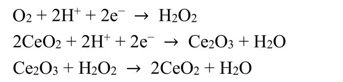
Furthermore, some reports discussed the accessibility of ironfree based cathode to avoid the effect of H2O2 and made progress in this direction26,27,33.
3.4 Micropore flooding
As mentioned above, micropores play an essential role in hosting active sites, the flooding of micropore may cause the loss of fuel cell performance. Dodelet et al.106proposed that the micropore flooding may degrade the fuel cell and reported a chronoamperometry curve to present the decay process, as shown in Fig. 17. They found that there was a dependence between the catalyst stability and the number of surface micropores. The high ratio of micropores led to excellent ORR activity but lower stability of catalysts. Based on this observation, they attributed the first rapid decay of current density in Zone Ⅰ in Fig. 17 to the flooding of micropores. They presumed that the slow oxidation of carbon support would occur in the first 15 h fuel cell operation, giving hydrophilic functionalities (R―CS―OH, R―CS=O, and R―CSOOH) and leading to the micropore flooding issue. Such an issue may trouble the mass transfer because the oxygen could not easily dissolve in water and reach the active sites.
However, a debate was then raised on whether micropore flooding is the direct reason for initial performance loss107.Dodelet’s group88accordingly revised their theory about micropore flooding. It was proposed that the water in the micropores contributed to the degradation of PGM-free PEMFC by flushing the metal ions out of the micropore network, causing the loss of active sites. To address the issue of micropore flooding, a surface fluorination strategy has been proposed by Sun’s group98. After grafting with the hydrophobic trifluoromethylphenyl (Ar―CF3) group, the modified surface could not only be anti-flooding but also alleviate the carbon oxidation (Fig. 18a). The modified catalyst exhibited superior durability with a stable current density in 100 h at 0.5 and 0.6 V,significantly outperforming the unmodified catalyst (Fig. 18b,c). Moreover, the strategies increasing the graphitization of carbon support while simultaneously enhancing hydrophobicity to reduce the risk of water flooding have also been attempted by several groups108,109.

Fig. 18 (a) Schematic comparison for hydrophilic and hydrophobic catalysts against water flooding and carbon corrosion;(b, c) stability comparison of Fe/N/C (black) and Fe/N/C-F (purple) in the H2-O2 fuel cell tests at 0.5 V (b) and 0.6 V (c).
In summary, despite the significant advances of M-N-C catalyst activity have made, the extremely poor stability still restricts its application on the PEMFC. The challenge of the activity degradation is multifaced, which involving the decomposition of metal species, the protonation of nitrogen sites, the carbon support corrosion, and the micropore flooding phenomenon. Owing to the unique design and synthesis strategy,the major degradation mechanism of various catalysts is different. Therefore, present proper strategies to improve its lifetime remains a great challenge. Fortunately, a series of approaches have been proved to be effective for addressing the mentioned degradation issues. Based on the degradation mechanism mentioned above, four main strategies are concluded and presented: (1) constructing exclusive and highly active M―Nxsites by designing rational synthesis procedures to decrease the field of H2O2and Fe-free catalysts. For example,Mn―N4or Co―N4active sites showed better stability because they avoided possible Fenton reactions26,27,33. (2) Enhancing the carbon support anti-corrosion capacity by increasing the degree of graphitization, such as increasing the pyrosis temperature or using metal nanoparticle to catalyze the growth of carbon nanotube. (3) The process of hydrophilic/hydrophobic modification of catalyst surface can be adopted to mitigating the micropores flooding. (4) The distribution of ionomer in CCL is not only vital to the activity of the device as discussed above, but also makes a difference to the stability of PGM-free PEMFC due to proper content of ionomer causes fewer problems of water flooding.
4 Summary and outlook
Stimulating by commercial applications, the increasing cost concerns of PEMFC have been encouraging the development of PGM-free PEMFC with both sufficient activity and stability although it is still challenging. The major bottleneck lies in the sluggish cathodic reaction, calling for strenuous efforts on understanding the genuine active sites in the catalysts for ORR,developing suitable and scalable synthetic protocols for highly active and robust catalysts as well as rationally designing the structure of cathode catalyst layer in M-N-C-based PEMFC.
4.1 Catalytic active sites
Tuning the coordination structure of M―N4and/or harnessing the interaction between metal and support to modulate the electronic structure of metal centers are of benefit to enhance the intrinsic activity of catalysts and result in the performanceboosting of PGM-free PEMFC. Simultaneously, increasing the density of accessible active sites by engineering the porous structure of the catalyst would enable more active sites to participate in the reactions and thus improve the activity of PGM-free PEMFC. To rationalize the design and synthesis of high-performance M-N-C catalysts, in situ advanced technologies combing with electrochemical testing as well as theoretical analyses are essential for a better understanding of the relationship between active sites and fuel cell performance.
4.2 Catalyst layer structure
The structure of both catalyst itself and the assembled cathode layer plays a vital role in improving mass transfer and charge transport. Different from the ideal conditions in RDE measurements, the reactions during the operation of fuel cell occurs at the interface of solid catalyst-liquid electrolyte-gaseous hydrogen/oxygen, commonly accompanying with serious mass transfer issues to hinder the utilization of active sites. Therefore,constructing catalysts with a suitable porous structure will be an effective approach to enhance the accessibility of active sites.Moreover, considering the MEA performance, how to integrate the catalyst ink onto the cathode to deliver the appropriate structure need to be paid more attention. Numerous factors such as the ionomer content, the size of catalyst particles, and the fabrication process of CCL, etc. may affect the performance of M-N-C MEA. The engineering of these parameters and the understanding of underlying sciences would advance the optimization of MEA for a given catalyst.
4.3 Catalyst durability
PEMFC has emerged as a promising power alternative in electric vehicles. It requires a stable operation in a reasonable lifespan, which cannot be fulfilled by the state-of-the-art PGM-free PEMFC yet. For the promising PGM-free M-N-C catalysts,the degradation mechanisms for M-N-C sites in acidic conditions should be further understood. The exact reason for initial performance loss is still unclear while the demetallation,carbon corrosion, and micropore flooding issues should be circumvented for M-N-C catalysts. Deeper insights into the degradation phenomena call for advanced multi-scale in situ characterization and monitoring technologies from atomic-level to device-level. Some strategies have been proposed to enhance the durability of PGM-free PEMFC, nevertheless, the activity of such devices was also traded off. New strategies should be proposed to figure out how to meet durability requirements while enhancing the activity of current PEM-free catalysts.
In summary, the M-N-C-based PEMFC is an on-going and promising approach to the commercial scale-up of fuel cells although the big gap remains between lab research and commercial expectation. As discussed above, the major limitations of M-N-C-based PEMFC come from the insufficient activity and durability of PEM-free catalysts. In terms of activity, besides the efforts on rationally designing highly-active PGM-free active sites for ORR, attention should be also paid to simultaneously construct effective tri-phase interfaces and channels for facilitating both mass transfer and charge transport at the device level. It should be kept in mind that only accessible active sites could take part in the reactions during harsh operation conditions. The design of the suitable porous structure with optimized pore size distribution would be an effective strategy to enhance the accessibility of active sites without bringing transfer issues. The structural engineering of CCL is equally important to maximize catalyst activity. Furthermore,enhancing the stability of M-N-C PEMFC remains a great challenge. Although tremendous efforts have been attempted to improve the stability, the results are currently far below practical targets. The underlying sciences should be disclosed with the aid of emerging multiple-scale in situ probing techniques and the materials innovations on catalysts might be needed to make a breakthrough.
杂志排行

物理化学学报的其它文章
- Enhanced Performance and Durability of High-Temperature Polymer Electrolyte Membrane Fuel Cell by Incorporating Covalent Organic Framework into Catalyst Layer
- Formic Acid Electro-Oxidation Catalyzed by PdNi/Graphene Aerogel
- 金属卟啉修饰的多孔聚苯胺基氧还原电催化剂
- 有序金属间化合物电催化剂在燃料电池中的应用进展
- 高温聚合物电解质膜燃料电池膜电极中磷酸分布及调控策略研究进展
- 提升燃料电池铂基催化剂稳定性的原理、策略与方法