Universal quantum control based on parametric modulation in superconducting circuits*
2021-07-30DanYuLi李丹宇JiChu储继WenZheng郑文DongLan兰栋JieZhao赵杰ShaoXiongLi李邵雄XinShengTan谭新生andYangYu于扬
Dan-Yu Li(李丹宇) Ji Chu(储继) Wen Zheng(郑文) Dong Lan(兰栋) Jie Zhao(赵杰)Shao-Xiong Li(李邵雄) Xin-Sheng Tan(谭新生) and Yang Yu(于扬)
1National Laboratory of Solid State Microstructures,School of Physics,Nanjing University,Nanjing 210093,China
2Shenzhen Institute for Quantum Science and Engineering,Southern University of Science and Technology,Shenzhen 518055,China
Keywords: superconducting qubits,parametric modulation,single-qubit gate,iSWAP gate
1. Introduction
Recent progress shows that superconducting quantum circuit is one of the most promising candidates for quantum computing.[1-4]While quantum chips with hundreds of qubits can be expected in the near future,[5,6]the expansion of electronic devices for quantum control has become a significant problem. There is an urgent need for a scalable and economical control scheme.
The frequency of superconducting qubits generally lies in a range of 4 GHz-10 GHz.[7-9]To manipulate the qubits,sequences of microwave pulses with a duration from tens to hundreds of nanoseconds are injected into the quantum chip through control lines. Although such microwave pulses can be directly generated by digital-to-analog converters(DACs)with a high sampling rate,[10,11]the instruments are not economical for widespread integration. Currently, the up-conversion technology is widely used. The microwave signal is produced by mixing up a continuous microwave with intermediate frequency (IF) pulses, utilizing an IQ mixer. The IF pulses are produced by DACs with sampling rates of a few gigahertz.This method has the following drawbacks: (i) Each qubit requires at least two DACs and an IQ mixer for up-conversion,which has become a great cost when scaling up;(ii)Since the electrical performance of the mixer varies due to manufacturing and environmental influence, regular calibration is necessary to suppress image tones and carrier leakage.[12]The careful calibration of hundreds of IQ mixers regularly becomes a daunting task in real experiments. Besides, additional hardware is needed for the calibration,such as spectrum analyzers.To alleviate these problems,some efforts have been made recently by hardware improvement.[13,14]
In this paper, we propose a simple and economical universal control scheme based on parametric modulation,[15-20]which provides a solution from another aspect. In the scheme,a continuous microwave signal is used as a global pump for all qubits in the chip. Each qubit is individually controlled by a sub-GHz parametric signal through itsZcontrol line. Both single-qubit manipulations and two-qubit gates can be realized through parametric modulation. The control scheme gets rid of IQ mixers, dramatically simplifies the input chain and reduces the potential source of errors. The demand for DACs has also been halved, reducing the cost. The rest of this paper is organized as follows. We introduce the control scheme and compare it with conventional methods in Section 2. We explain how to construct universal quantum gates using parametric modulation in Section 3 and analyze the control fidelity in Section 4. We summarize the article in the last section.
2. Control scheme
We illustrate our control scheme in Fig. 1(a). A continuous pump signal is injected into the quantum chip through a common drive line,which is coupled to all qubits. The pump signal drives all the qubits non-resonantly. Since the effective drive amplitude on the qubits (tens of megahertz in Rabi frequency)is generally much smaller than the frequency detuning between the qubits and the pump signal,negligible excitation is caused.
To perform gate operations, we parametrically modulate a qubit’s frequency with a sinusoidal pulse,through its Z control line. When the frequency of the modulated pulse closely resonates with the detuning between the qubit and the pump signal,single-qubit excitation can be achieved. Two-qubit operations (typically iSWAP-type gates) are realized when the modulation frequency is closely resonant to the detuning between two coupled qubits.
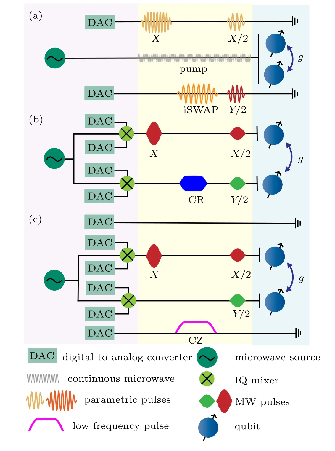
Fig.1. Illustration of three control schemes: (a)full parametric modulation;(b)full microwave control; (c)hybrid control including microwave control and frequency modulation. The left side shows the electronic circuits of the schemes and the middle part illustrates pulse sequences. The right side represents the quantum devices. For simplicity, control schemes for two coupled qubits are shown.
In the gate scheme, all pulses are directly produced by DACs, without using any IQ mixer for up-conversion. Since the single-qubit gates(SQGs)and iSWAP gates can share the same control line and DACs,anN-qubit chip can be fully controlled byN Zcontrol lines andNDACs. The frequency difference between qubits and the pump signal is about 1 GHz-2 GHz, which means the sampling rate of DACs needs to be about 5 GHz. To reduce the limitations of the scheme, the qubit(typically transmon)can be biased at its sweet spot and the modulation frequency is then halved.[15,16,21,22]Therefore,DACs with a sampling rate of 2 GHz-3 GHz are sufficient for gate operations in experiments (See Supplementary material for details).
Our gate scheme is fully based on the parametric frequency modulation of the qubits. We compare our scheme with conventional control schemes which are based on full microwave modulation[23-26]and the hybrid control.[4,27]In the full microwave scheme,both SQGs and two-qubit gates(typically CR gates) are realized with microwave pulses, which are upconverted from a continuous microwave using IQ mixers. SQGs and two-qubit gates share the same control line and room temperature equipments. In this scheme,two DACs and one mixer are needed to manipulate one qubit, see Fig. 1(b).In the hybrid control scheme, the SQGs are realized by upconverted microwave pulses injected through theXYlines,and two-qubit gates are realized by low-frequency pulses injected through theZlines, see Fig. 1(c). Although theZline andXYline can be merged in circuit design,[1,28]the microwave excitation and the frequency modulation still need independent DACs for control. Therefore,in the hybrid scheme,each qubit needs 3 DACs (two for microwave control and one for frequency modulation)and one mixer. The comparison shows that our scheme greatly simplifies the control system and completely gets rid of IQ mixers. Generally,each pump signal can control tens of qubits,with the frequencies of the qubits alternately arranged. For larger-scale quantum computation,more than one pump signals can be introduced.
Although parametric modulation is preferred in our proposal,it is feasible to construct SQGs(iSWAP gates)by tuning qubit frequency into resonance with the pump frequency(frequency of neighboring qubit). However, there are two drawbacks in the latter case: i) The frequency crowding problem:during gate operations,the system may pass through unwanted crossings with neighboring qubit’s energy levels,causing state leakage; ii) Generally, the qubits are idly biased at the sweet spot with longer coherent time.Strongly tuning the qubit away from the sweet spot will cause severe decoherence. The parametric modulation enables frequency-selective gates and can effectively avoid these two problems.
3. Universal quantum gates based on parametric modulation
In this section, we theoretically explain how the SQGs and the iSWAP-type gates are constructed in our control scheme. For simplicity, here we consider two coupled qubitsQ1andQ2. The coupling strength between the two qubits isg12. The frequency of each qubit is tuned by an external flux signal. A global pump signal of amplitudePis injected into the quantum chip. The system Hamiltonian is(set ¯h=1)


3.1. Single-qubit gates
For SQGs, we consider the single qubitQ1. The corresponding modulation signal is in derivative formξ1(t)=ζ′1(t),whereζ1(t)=A(t)sin(Δp1t+φf).Using Jacobi-Anger expansion,the first three terms in Eq.(3)becomes


where Jn(z)is then-th-order Bessel function of the first kind.The rapid oscillation terms in the expansion are omitted using RWA,the effect of these terms will be discussed in Section 4.The phaseφfcontrols the direction ofXYrotation and

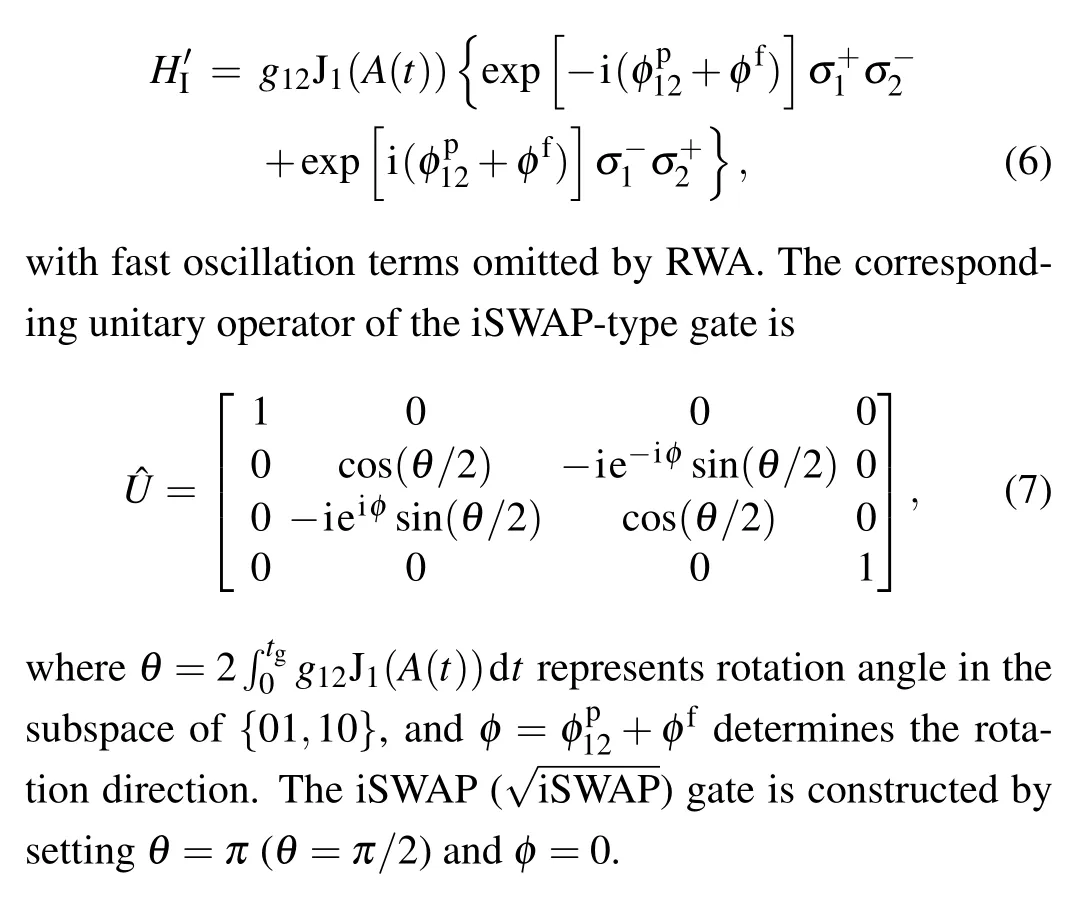
3.2. iSWAP-type gates
For two-qubit gates between two coupled qubitsQ1andQ2, we consider a sinusoidal signalζ1(t)=A(t)sin(-Δ12t+φf) onQ1(andζ2(t)=0 onQ2). The effective interaction Hamiltonian betweenQ1andQ2is
3.3. Phase accumulation

In real experiments, the non-resonance terms in the Jacobi-Anger expansion will cause frequency shift of the qubits during parametric modulation, known as Stark shift.[31,32]The frequency shift will introduce an additional phase accumulation on the qubits. The phase accumulations become more complicated when considering higher energy levels and nonlinear frequency response to external signal(Ref.[15]and Supplementary material). The phase accumulations can be measured by Ramsey experiments and cancelled by virtualZgates.[29]
It is worth mentioning that the actual frequency modulationξ(t)is the derivation of primitive function:ξ(t)=ζ′(t)=A′(t)sin(ωt+φf)+ωA(t)cos(ωt+φf).ξ(t) is also a sinusoidal modulation,the phase ofξ(t)is

If the envelopeA(t)is slowly varied compared toω(A′(t)≪ωA(t)),the phase can be approximated byφm=φf.
4. Error analysis
In the above discussion, only the resonant term (n=1)in the Jacobi-Anger expansion is considered. While the nonresonant interaction terms (n/=1) may cause unwanted transition and damage the control fidelity. We can use a simplified Rabi model to estimate the transition errors. During the parametric control,both the interaction strengthΩand the detuningΔof a non-resonant interaction in the Rabi model are treated as constants. The transition rate caused by the nonresonant interaction is

In the case of large detuning(Δ ≫Ω~1/Tgate),εis a rapid oscillation term. We use the average value to evaluate the gate error, the transition rate can be simplified asε ≃Ω2/2Δ2.Since typical superconducting qubits such as transmons and C-shunted flux qubits are weakly anharmonic,[33,34]the error analysis should include the second excitation level. Thus,the lowest three levels of each qubit are considered in the following discussion.
4.1. Errors of the parametric SQGs
With the sinusoidal modulationζ(t)=A(t)sin(ωt+φf),the Hamiltonian for the parametric SQGs is

whereα1is the anharmonicity of the qubitQ1andΔp1is the detuning between pump signal andQ1.B=λPdenotes the effective pump strength on the qubit.
The parametric SQGs are realized by setting the first order Bessel interaction into resonance (ω=Δp1,n=1). All the other terms are non-resonant interactions,the corresponding interaction strength and the estimated error rates with typical parameters are shown in Table 1. According to Eq. (9),the terms with relatively small detuning and large interaction strength generally cause dominant errors. Assuming the modulation amplitude is smaller than the detuning(|A(t)|<1),the terms withn >1 andn <0 can be neglected since these terms have both small interaction strength and large detuning. Notice that the transition errors should be multiplied by an extra factorf. For example, the error rates caused by interactions in subspace{|1〉,|2〉}should be multiplied byf=0.5, since such an interaction has no effect if the qubit is in state|0〉.
All transition errors scale quadratically with the pump strengthB, as shown in Fig. 2(a). Since J0(A(t))~1 withA(t)<1, the 0th-order error is almost independent of the modulation amplitudeA(t). But the 1st-order interaction in{|1〉,|2〉}subspace is strongly related to the modulation amplitude. This error becomes dominant with largeA(t),shown as the dashed blue line in Fig.2(a). There is a trade-off between the gate time and the transition errors. Stronger pump strengthBor modulation strengthA(t) will result in shorter gate time but cause more transition errors. In all,we find that total error rates are smaller than 0.1%,with a gate time of about 60 ns.
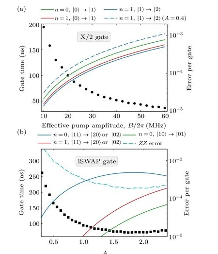
Fig.2.Error analysis of parametric modulation.(a)Gate time(black circles)and transition errors(solid lines)of X/2 gate versus pump strength B,with modulation factor A=0.27. The detuning between qubit’s frequency and the pump frequency is Δp1/2π =1.5 GHz. The anharmonicity of the qubit is α1/2π =-250 MHz. State leakage arising from 1st-order Bessel interaction becomes dominant in case of strong modulation amplitude(A=0.4),shown as the dashed blue line. (b)Gate time(black squares)and transition errors(solid lines)of iSWAP gates versus modulation factor A. The detuning between the two qubits is Δ12/2π=800 MHz and the coupling strength strength is g12/2π =6.7 MHz. The anharmonicities of both qubits are set as-250 MHz. The dashed black line shows the ZZ interaction error during the parametric modulation.
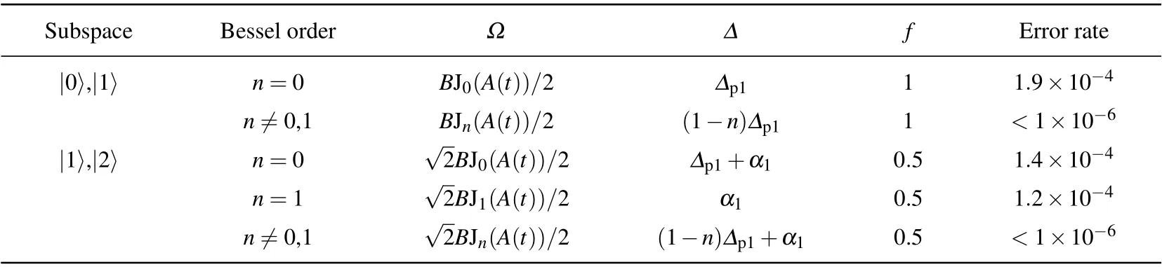
Table 1. Non-resonant interactions in a parametric SQG.The error rates are evaluated as(Ω2/2Δ2)f,with B/2π=30 MHz,Δp1/2π =1.5 GHz,α1/2π =-250 MHz,and A(t)=0.27.
4.2. Errors of the iSWAP gate
Similar error analysis can be given to the iSWAP gates.The interaction Hamiltonian for two-qubit gates betweenQ1andQ2is

The resonant condition isΔ12+ω=0. We show the nonresonant interaction terms in Table 2. Error rates caused by the terms withn >1 orn <0 are negligible. Notice that the strength of 0th-order interaction is in form of 1-J0(A),instead of J0(A), in the dressed eigenstates basis. The corresponding error rates of iSWAP gatesversusmodulation amplitude are shown in Fig. 2(b). The 1st-order terms in the subspace of{|11〉,|20〉}and{|11〉,|02〉}are the dominant sources of errors.
In addition to transition errors, there is also intrinsicZZerror. TheZZcoupling strength is defined asη=ω11+ω00-ω01-ω10.[35-37]Due to the level repulsion effect of higher levels, theZZcoupling strength between two coupled qubits is[38,39]
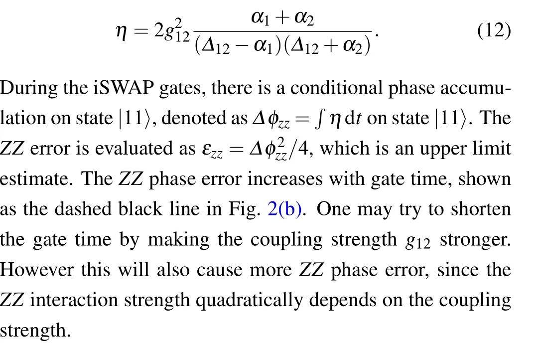

Table 2. Non-resonant interactions in a parametric iSWAP gate. The error rates are calculated with g12/2π =6.7 MHz,Δ12/2π =800 MHz,α1/2π =α2/2π =-250 MHz,and A(t)=1.
5. Summary
We propose a universal control scheme based on parametric frequency modulation. By halving the required DAC,this control scheme effectively saves the cost of large-scale quantum control. The input system has been greatly simplified.Because no IQ mixer is used, complicated calibration work is avoided. We theoretically explain how the universal gates are constructed by introducing a global microwave pump. The fidelity analysis shows that The error rate of parametric control is below 0.1% with a typical gate time of 60 ns (100 ns)for single-qubit (two-qubit) gates, proving its potential for a broad application.
杂志排行

Chinese Physics B的其它文章
- Projective representation of D6 group in twisted bilayer graphene*
- Bilayer twisting as a mean to isolate connected flat bands in a kagome lattice through Wigner crystallization*
- Magnon bands in twisted bilayer honeycomb quantum magnets*
- Faraday rotations,ellipticity,and circular dichroism in magneto-optical spectrum of moir´e superlattices*
- Nonlocal advantage of quantum coherence and entanglement of two spins under intrinsic decoherence*
- Universal quantum circuit evaluation on encrypted data using probabilistic quantum homomorphic encryption scheme*