Recent Progress of Perovskite Oxide in Emerging Photocatalysis Landscape: Water Splitting, CO2 Reduction, and N2 Fixation
2021-07-13ZejianWangJiajiaHongSueFayeNgWenLiuJunjieHuangPengfeiChenWeeJunOng
Zejian Wang , Jiajia Hong , Sue-Faye Ng , Wen Liu , Junjie Huang , Pengfei Chen ,4,Wee-Jun Ong 2,,5,*
1 School of Materials Science and Engineering, Wuhan University of Technology, Wuhan 430070, China.
2 “Zhucai” Center of Innovation and Entrepreneurship, Wuhan University of Technology, Wuhan 430070, China.
3 School of Energy and Chemical Engineering, Xiamen University Malaysia, Selangor Darul Ehsan 43900, Malaysia.
4 State Key Laboratory of Silicate Materials for Architectures, Wuhan University of Technology, Wuhan 430070, China.
5 College of Chemistry and Chemical Engineering, Xiamen University, Xiamen 361005, Fujian Province, China.
Abstract: At present, more than 80% of the world's energy demand is fulfilled by the burning of fossil fuels, which has caused the production of a large amount of greenhouse gases, leading to global warming and damage to the environment. The high consumption of fossil fuels every year causes the energy crisis to become increasingly serious. Finding a sustainable and pollution-free energy source is therefore essential. Among all forms of energy sources, solar energy is preferred because of its cleanliness and inexhaustible availability. The energy provided by one year of sunlight is more than 100 times the total energy in known fossil fuel reserves worldwide; however, the extent of solar energy currently used by mankind each year is minute; thus developments in solar energy are imperative. To address the urgent need for a renewable energy supply and to solve environmental problems, a variety of technologies in the field of photocatalysis have been developed. Photocatalytic technology has attracted significant attention because of its superior ability to convert clean solar energy into chemical fuels. Among the photocatalytic materials emerging in an endless stream, perovskite oxide, with the general formula of ABO3, has great potential in the fields of solar cells and photocatalysis as each site can be replaced by a variety of cations. Furthermore, owing to its unique properties such as high activity, robust stability, and facile structure adjustment, perovskite oxide photocatalysts have been widely used in water decomposition, carbon dioxide reduction and conversion, and nitrogen fixation. In terms of carbon dioxide reduction,oxide perovskites can achieve precise band gap and band edge tuning owing to its long charge diffusion length and flexibility in composition. For the development and utilization of solar energy in the environmental field, perovskite oxide and its derivatives (layered perovskite oxide) are used as photocatalysts for water decomposition and environmental remediation. In terms of nitrogen fixation, the conventional Haber-Bosh process for ammonia synthesis, which has been widely used in the past, requires high temperature and high energy. Therefore, we summarize the recent advances in perovskite oxide photocatalysts for nitrogen fixation from the aspect of activating the adsorbed N2 by weakening the N≡N triple bond, promoting charge separation, and accelerating the charge transfer to the active sites to realize the photochemical reaction. Overall, this review article presents the structure and synthesis of perovskite oxide photocatalysis,focusing on the application of photocatalysis in water splitting, carbon dioxide reduction, and nitrogen fixation. This review concludes by presenting the current challenges and future prospects of perovskite oxide photocatalysts.
Key Words: Perovskite oxide; Photocatalysis; Carbon dioxide reduction; Water splitting; Nitrogen fixation
1 Introduction
With the development of mankind and the progress of society,people’s demand for various energy sources is increasingly expanded, and the degree of development and utilization is much higher than before. At the same time, the threat of energy shortage and environmental pollution has become more imminent day in day out1–6. The overuse of traditional fossil fuels releases a large amount of carbon dioxide, which is beyond the capacity of our atmosphere, leading to the destruction of the carbon cycle, and ultimately causing the greenhouse effect7–13.In addition, polluted wastewater flowing into the ecosystem will become an important source of ecology pollution, eutrophication and disturbance to aquatic organisms14–21. In this regard,research on photocatalytic technology that utilizes solar energy has shown remarkable development in the control of greenhouse gas emission and the degradation of organic matter in the wastewater4,22–27. What is more, solar energy is a renewable and easily available energy source, emitting around 3.85 × 10⁶EJ of energy that is absorbed by the land every year, which will be adequate to meet the rising demand for energy if harnessed.However, solar energy utilized by humans is far below 1%28.Thus, photocatalysis is a way to effectively take advantage of solar energy to convert the H2O, CO2and N2into energy-rich products2such as H2, CH4, CH3OH and NH3through the decomposition of water to produce H229–46, the reduction of CO247–66, the fixation of N267–86, and the decomposition of organic pollutants87–93.
Since Fujishima and Honda firstly realized photocatalytic water splitting in 197294, people have continued to study photocatalysis due to its good stability, non-toxicity, and easy production. However, the commercial TiO2photocatalyst possesses a wide band gap (3.2 eV), thus leading to its excitation by ultraviolet light with a shorter wavelength only, which is not satisfactory for optimum solar light utilization4,5. Also, when taking into consideration that the high recombination rate of photo-induced electrons and holes leads to poor photocatalytic efficiency, there exists an urgent need to find a more suitable semiconductor.
In recent years, perovskite oxides have been widely studied in the energy field in the form of perovskite solar cells due to their unique properties (i.e.tunable band structure, flexible structure,and high carrier mobility)95–98. In addition, their distinct structural and physical advantages have brought about their subsequent rise to attention as a promising photocatalyst, and thus have been extensively studied such as CaTiO3, SrTiO3,NaNbO3and SrSnO399–103. However, many existing perovskite oxides suffer from a weak light-harvesting ability due to their large bandgaps (e.g. CaTiO3: 3.62 eV, NaTaO3: 4.0 eV, KTaO3:3.75 eV) that become a bottleneck for maximum utilization of solar energy. The large bandgaps of the semiconductors suggest a narrow absorption range of the solar light, which does not necessarily indicate a weak light harvesting ability. Owing to the structure tuning, perovskite-type semiconductors are able to exhibit different bandgaps (e.g. LaFeO3: 2.0 eV, LaTiO2N: 2.1 eV)104, broadening the possibility to find or design new materials with a high light absorption capacity. Besides, the facile preparation renders perovskite-type material a costeffective alternative.
In this review, we have summarized the structure and synthesis methods of perovskite oxides with a brief introduction about of the advantages of “perovskite-type”. Then a detailed discussion is given on the latest reports about perovskite oxides applied in the field of photocatalytic water splitting, CO2reduction N2fixation, and photocatalytic degradation. In order to enhance the photocatalytic efficiency, modification strategies such as doping and heterostructure engineering are discussed.Additionally, the problems existing in the application of perovskite oxide catalysts are reviewed, and the future research direction of perovskite oxide catalysts is prospected.
2 Advantages and disadvantages of perovskite oxide for photocatalysis
Generally, the photocatalytic process can be divided into three steps. As shown in Fig. 1a, electrons are excited to the conduction band (CB) under illumination and leaving holes in the valence band (VB)105. Subsequently, the photocharges are separated and transferred to the surface of photocatalyst.However, some charge carriers will recombine with the corresponding opposite carriers in the bulk of the photocatalyst or on the photocatalyst surface, thus increasing the recombination process. Finally, once charge carriers are successfully migrated to the surface, they participate in the redox reaction with the adsorbed molecules.
As is known to all, the position of energy band in the photocatalyst plays a decisive role in photochemical reaction.The bottom of the CB and the top of the VB must be higher and lower than the oxidation-reduction potentials, respectively.Taking water splitting for example (Fig. 1b), the position of CB should be higher (more negative) than the reduction potential of H+/H2(0 Vvs.normal hydrogen electrode (NHE) at pH 0), while VB should be lower (more positive) than the oxidation potential of O2/H2O (+1.23 Vvs.NHE at pH 0)32. On this basis, the narrower band gap allows for wider light absorption range,which may be up to the visible light region. Additionally, the separation and transport of charge carriers is of utmost significance.
The perovskite oxide (ABO3) has been propelled to the forefront in photocatalysts due to its semiconducting and lightharvesting properties. The origin of such properties is inextricably associated with the unique crystal structures of ABO3. Perovskite oxide, known as a ceramic oxide, is a class of mineral compound with a general formula of ABO3. The A site is generally a larger rare earth cation or alkaline earth ion, and the B site is a smaller transition metal ion, and the O is the oxygen, which bonds to the A and B metal ions94. As shown in the Fig. 2a, more than 90% of elements can be combined with the crystal lattice of perovskite oxide, on account of the structural specificity that a plenty of metal ions can be placed in the A site (i.e.Ca2+, Sr2+, Na+) and the B site (i.e.Ti4+,Nb5+,Sn4+)106,107.
The ideal perovskite ABO3is a cubic crystal system (Fig 2b),such as CaTiO3, in which A site is Ca2+and located at eight vertices of the regular cube, O site is occupied by the O2−and six O2−to form an oxygen octahedron where O2-is located at six vertices, and B site is Ti4+, in the co-center position of the regular cube and the oxygen octahedron. From Fig. 1b, it can be demonstrated that there are 12 oxygen coordination per Ca2+in the complete crystal form, and each O2−is connected to 6 cations including four Ca2+and double Ti4+108. Additionally, the construction of the ions follows the equation:rA+rO= 2 (rB+rO), whererA,rBandrOare the radii of the A, B, and O ions,respectively.
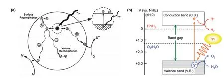
Fig. 1 (a) Basic principles of photocatalysis on semiconductor 105. Reproduced with permission from American Chemical Society.(b) Mechanisms of photocatalytic overall water splitting 32. Reproduced with permission from American Chemical Society.

Fig. 2 (a) Element composition of reported perovskite oxide-based photocatalysts for CO2 reduction 106.Reproduced with permission from Wiley-VCH. (b) The structure of ABO3.

Fig. 3 Schematic crystal structures of (a) the monoclinic NaTaO3; (b) the orthorhombic NaTaO3 110. Reproduced with permission from Elsevier.(c) Schematic crystal structures of cubic, orthorhombic and tetragonal KNbO3 109. Reproduced with permission from Royal Society of Chemistry.
It is noteworthy that not all perovskites can have a perfect cubic crystal system, as some of them will undergo a structural transformation. Herein, the Goldschmidt tolerance factor (t) is usually used to predict the formability and phase stability of perovskite structure. The expression of the tolerance factor ist=rA+rO/ 2 (rB+rO), whereby the ions of the constituent elements must satisfy the tolerance factor (t): 0.75 ≤t≤ 1.0107.Beyond that, different distortions of the perovskite structure will appear (i.e.orthogonal, tetragonal, and monoclinic phase) (Fig.3), which relies on the ionic radii and electronegativity of the A and B site cations109,110.
From the point of view of photocatalysis, perovskite structures exhibit following commendable advantages:
(1) The perovskite structure offers a flexible framework for a broad scope of A and B site cations, thus leading to the adjustable band gap values for visible-light absorption and favorable band edge potentials for various photocatalytic reactions. Fig. 4 shows the reduction potential values of general photocatalytic reactions and the band structure of several perovskites13. For example,several perovskites such as SrTiO3and LaFeO3have shown visible-light activity with enough CB potential for hydrogen evolution.
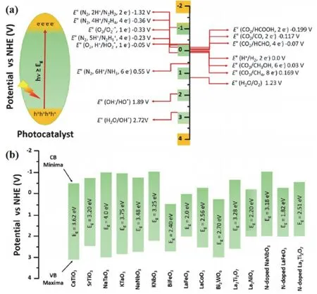
Fig. 4 (a) Schematic of photoexcitation in a photocatalyst and the redox potential values for the formation of different products at pH = 0 vs. NHE. (b) Band gap and band positions of pristine and doped perovskite materials 13. Reproduced with permission from American Chemical Society.
(2) The lattice distortion in perovskites dramatically influences the dipole moment and electronic structure, giving rise to different crystal fields, which strongly affect the excitation, separation and transfer of photogenerated charge carriers. For example, the octahedral tilting distortion of SrSnO3is beneficial for the migration of electrons or holes111.
(3) Some studies have shown that it is possible to combine the effects such as ferroelectricity or piezoelectricity with the photocatalytic effect to benefit the photocatalytic activity112.
(4) Perovskite material can be tailored facilely through doping, morphology control and heterostructure construction to boost the photocatalytic efficiency.
Nevertheless, perovskite oxides are also faced with some stumbling blocks:
(1) Most perovskite oxides possess a large band gap rendering only UV light absorption, which limits the utilization of solar energy and the quantum yield.
(2) The high rate of charge recombination leads to decreased catalytic activity.
(3) The small surface area limits the reactant contacted on surface as well as the catalytic sites.
In view of the above disadvantages, several effective means have been adopted to resolve the shortfall and further improve the photocatalytic activity, including doping113–117, employing co-catalyst31,103,118–120, heterostructure construction26,121–127,morphology and crystal controlling107,128–131.
3 Modification strategies of perovskite oxide for photocatalysis
According to the photocatalysis principle, the basic steps include: (i) Light excitation. An ideal semiconductor photocatalyst should possess an appropriate bandgap to absorb visible light. Band engineering and defect engineering have been widely used for the modification of bandgap structure and to enhance the innate light absorption capabilities132,133. (ii) Charge separation and transport. The recombination of photogenic carriers will result in energy loss, thus the suppression of charge recombination merits attention. The internal electric fields formed by heterojunctions can prolong the exciton lifetimes effectively134. Shape and facet engineering have also been developed to promote charge separation and transport135. (iii)Surface chemical reaction. The deposition of cocatalysts has been considered as a simple and reliable technique to reduce the overpotentials for H2and O2evolution as it facilitates the surface chemical reaction and hinders the backward reaction136.
A myriad of studies have covered in-depth modification of perovskite oxide thus far.
3.1 Doping
Doping is one of the most common strategies to adjust the band gap of perovskite photocatalyst, leading to enhanced light absorption of visible and NIR light. For perovskite oxide, doping can be achieved at three sites (A, B, O), which compensate for the weakness of wide band gap. Doping causes three changes in the electronic band structure of the semiconductors (Fig. 5): (i)Creating intraband energy states (Fig. 5b)137. The doping can create shallow and deep intraband energy levels, which function as the dominant centres for optical excitation and relaxation to extend the absorption tail of the absorption curve to longer wavelengths without affecting the band gap138. (ii) Narrowing of the bandgap (Fig. 5c)137. In this process, doping alters the position of conduction or valence band, resulting in narrowing of the bandgap, thus leading to a red-shift at the edge of the absorption spectrum137. This change results in a narrower band gap without the introduction of intraband energy states, which avails the light absorption138. (iii) Impurity band formation in degenerately doped transition metal semiconductors, which broaden the absorption range of the materials to a certain extent(Fig. 5d)137. On the whole, doping can enhance light absorption though bandgap shift, which will be validated repeatedly in the photocatalytic applications described later. Moreover, it is of high significance to find the most suitable amount for doping since this method can not only lead to active sites, suppressed carriers recombination and prolonged lifetime of electrons, but also result in recombination centers due to excessive defects.

Fig. 5 Schematic for bandgap engineering of semiconductors. The band structure and optical absorption curves of (a) an intrinsic semiconductor, (b) doping-induced intraband energy states, (c) doping-induced band gap narrowing and (d) degenerate doping-induced LSPR 137.Reproduced with permission from Royal Society of Chemistry.
3.2 Heterojunction
In the absence of any potential gradient, the migration of photogenerated charges mainly depends on the photogenerated charge carrier lifetime and the symmetry of the material. For perovskite oxide, high symmetry crystal structures often possess long carrier lifetime. However, the high rate of photogenerated charges recombination is an inherent defect of perovskite oxide,which limits the performance of photocatalysis. The construction of heterojunction can provide potential gradient and form a built-in electric fields to facilitate the separation of electrons and holes. Recent research has witnessed rapid advances in heterogeneous structures construction, including: (i)Type II heterojunctions. As shown in Fig. 6a, the band positions of the two semiconductors are staggered, in which the CB and VB of one semiconductor locate above another one11. Due to the potential gradient, the electrons at higher CB move downward to the lower one, while the holes in lower VB transfer upward to the higher one, thus give rise to an efficient separation of photogenerated charges. (ii)p-nheterojunction (Fig. 6b)11. The close contact betweenn-type semiconductor andp-type semiconductor not only possesses the merit of type II heterojunctions (potential gradient), but also forms a built-in electric fields to promote the separation of charges. (iii) Schottky junction (Fig. 6c)11. Schottky junction normally occurs between semiconductor and noble metal cocatalysts. Under the light irradiation, electrons in the semiconductor CB are transferred to the cocatalyst due to the lower Fermi level. On account of the presence of Schottky barrier, electrons are unable to return to the semiconductor to recombine with holes, thus improving the efficiency of charge separation. (iv) Z-scheme (Fig. 6d)11. In this mechanism, the holes in higher VB will combine with the electrons in lower CB and effectually prevent the photocorrosion during photocatalysis. This recombination of charges is accelerated by the built-in electric fields, so Z-scheme usually makes for high redox ability.
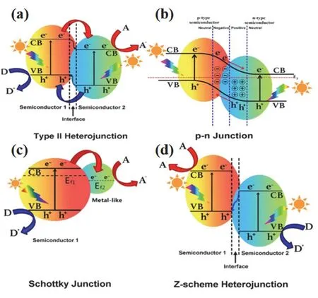
Fig. 6 Band structure of various types of heterojunctions in a photocatalytic hybrid composite: (a) Type II heterojunction, (b) p-n junction, (c) Schottky junction, (d) Z-scheme heterojunction 11.Reproduced with permission from Elsevier.
3.3 Crystal and morphology controlling
The lattice distortion in perovskites dramatically influence the dipole moment and electronic structure, thus giving rise to different crystal fields, which strongly affect the excitation,separation and transfer of photogenerated charge carriers. The high symmetry crystal structures often possess long carrier lifetime. Micron and nanostructured perovskite materials usually have higher specific surface areas to provide more active sites.Doping and defective engineering also play a critical role in lattice distortions, moreover, different synthesis can obtain controlled perovskite material with varied crystal structures,morphologies and sizes. Therefore, crystal and morphology controlling is a thriving area of research in perovskite oxides hitherto.
4 Synthesis
A wide range of approaches have been developed to synthesize perovskite oxides, including the sol-gel method,chemical coprecipitation process, combustion synthesis, solid state method, hydrothermal method and so on100,129,139–149.Besides, several new methods have been adopted to obtain the perovskite samples with enhanced stability, improved crystal structure with less defects. The near room temperature synthesis of perovskite oxide with high crystallinity is a promising way to effectively reduce the energy consumption required during synthesis150. In this way, perovskite oxide is prepared at room temperature using the reaction between alkaline earth metal hydroxides and metal oxide hydrogels, successfully producing highly symmetrical perovskite oxide at lower temperatures.Significantly, different synthesis methods will lead to different catalytic properties. Compared with La0.9Sr0.1CoO3prepared by sol-gel method, La0.9Sr0.1CoO3prepared by hard template (SBA-15) method had a better performance, which led to a decreased temperature at 50% conversion for CO oxidation from 186 to 146 °C. The ameliorated performance was attributed to the increase in surface adsorbed oxygen of the hard-template synthesized La0.9Sr0.1CoO3, which in turn stemmed from the higher surface area and smaller particle size151.
4.1 Sol-gel method
Sol-gel is a method in which compounds are solidified by solution, sol and gel in water or low-carbon alcohol solvents, and then heat-treated to prepare oxides, composite oxides and many solid substances. Due to the large number of liquid phase or pores present in the gel, the agglomeration of particles in the process of heat treatment is effectively prevented, and the product will have a good dispersibility. In the synthesis of LaFeO3adopted by Paridaet al.152, Fe(NO3)3·9H2O,La(NO3)3·6H2O and citric acid were dissolved in water, followed by adjusting pH to 7.0 and stirring the solution at 60 °C, adding stable nitrate sol, heating to 130 °C to form xerogel, and further heating it to obtain the product naturally.

The whole process was schematically represented in Fig.7a152. However, it is noteworthy that some of the shortfalls of this method are the large shrinkage, residual pores, high cost and cracking during drying, thus leading to the bottleneck of further industrial production and practical applications.
4.2 Chemical coprecipitation process
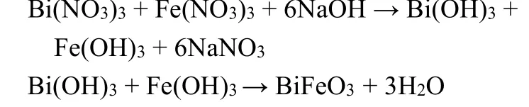
Chemical coprecipitation is a method to prepare materials by chemical reaction, which is filtered, washed, dried and decomposed by heating. The method is simple, economical and suitable for the preparation of powder products with high demand. Perovskite BiFeO3155has been synthesized using the chemical coprecipitation process with Bi(NO3)3·5H2O and Fe(NO3)3as the precursors, while NaOH was used as precipitant.
Pb(Fe0.5Nb0.5)O3was also prepared through the coprecipitation process as shown in Fig. 7b153. Although the chemical coprecipitation method can easily prepare perovskite,it is difficult to obtain ideal products due to different hydrolysis rates of polymetallic ions, leading to the decrease of catalytic activity156.
4.3 Hydrothermal synthesis
Hydrothermal is mainly employed in the material synthesized in the aqueous solution under the high temperature and the high pressure closed system followed by the steps of separation and post-treating. Cuiet al.154synthesized SrFe0.5Ta0.5O3nanoparticles with this process by adding sodium oleate to the absolute ethanol containing oleic acid and stirring vigorously (Fig. 7c). After the sodium oleate was completely dissolved, TaCl5, C15H21FeO6, and (C2H3O2)2Sr were sequentially added while stirring, the pH value of the mixture was adjusted to 12, and the mixture was stirred until the precipitation disappeared. Then, the obtained solution was cooled to room temperature, and the precipitate was collected by centrifugation, then washed and dried to obtain the product.BiFeO3was synthesized through the hydrothermal synthesis and then formed ap-nheterojunction with ZnO, which reached a CO2conversion efficiency of 21%52. The synthesis reaction mainly occurred as follow:
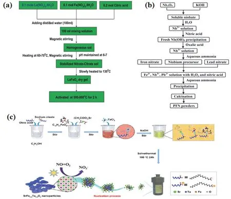
Fig. 7 (a) Schematic representation of LaFeO3 preparation 152. Reproduced with permission from Elsevier. (b) Schematic process for the preparation of PFN powders 153. Reproduced with permission from Elsevier. (c) Proposed synthesis process of SrFe0.5Ta0.5O3 nanoparticles via the low-temperature solvothermal method 154. Reproduced with permission from Elsevier.

Different synthesis routes provide a crucial basis of the morphologies and crystallinity of perovskite, which plays a functional role in photocatalytic performance. Hydrothermal synthesis is widely employed to prepare morphology-controlled perovskite materials and even adjust crystal from the nanoscale to the micron-scale157. A diverse range of perovskite material with different morphologies and crystallinity (i.e.large area nanocube-like ZnSnO3148, SrMnO3nanowire158, mesoporous spheres of NiMnO6159, rectangular prism-like CaTiO3particles149) prepared through hydrothermal has witnessed its huge superiority.
4.4 Solid state method
Solid state method has gradually become one of the most widely adopted strategies in perovskite synthesis, generally making use of metal oxides, carbonates, oxalates and other reaction precursors, and fully mixing and calcining with the reaction starting material. By mixing stoichiometric amounts of La2O3, Co2O3and NiO, along with a subsequent heat treatment at 900 °C and 1200 °C in the air for a certain period of time,perovskite LaCo1−xNixO3can be obtained160.
La2O3+ (1 −x)Co2O3+xNiO → 2LaCo1−xNixO3
This method is environment-friendly as no toxic gases will be released. However, it requires extremely high temperatures, and the size of prepared sample is relatively large with small specific surface area, low productivity, and insufficient mixing degree,which will affect the subsequent catalytic reaction.
4.5 Combustion synthesis method
Compared with the conventional solid-state method,perovskite with smaller particles and larger surface area can be obtained through the combustion synthesis method. LaFeO3was successfully synthesizedviacombustion method using La(NO3)3·6H2O and Fe(NO3)3·9H2O in the aqueous medium with glycine solution161.

In the process of preparing a series of macroporous cerium substituted La1−xCexCoO3catalysts162, the samples were obtained by composite combustion method using La(NO)3·xH2O, Ce(NO)3·6H2O and Co(NO3)3·6H2O as the precursors and ethylene glycol and methanol as complexing agents. The method is simple to operate and can reduce the calcination temperature and time, so the macroporous catalyst can be prepared more effectively.
5 Photocatalytic applications of perovskite oxide
5.1 CO2 reduction
As one of our main energy sources, fossil fuels have indeed accelerated the process of human community development,while carbon dioxide became the main greenhouse gas at the same time163–168. In recent years, the inexorable rise of carbon dioxide level in the atmosphere has already exceeded 400 × 10−6and the concentration of CO2has increased at a rate higher than that of 2 × 10⁻⁶every year, highlighting the need for reducing the present CO2emissions168–173. Therefore, the production of valuable chemicals or fuels using the greenhouse gas, CO2as a carbon source has been considered as a promising solution in dealing with the critical issues of energy shortages, clean energy production, and maintaining the normal carbon cycle to get the global environment back on track169,174–182.
However, due to the high bond energy of C―O bond (750 kJ·mol−1), which is much higher than that of C―H bond (411 kJ·mol−1) and C―C bond (336 kJ·mol−1), CO2embodies one of the most stable carbon compounds in thermodynamics and thus it is a significant task to convert CO2into the desired products20,183.Besides, the traditional thermal catalytic activation of CO2requires a higher temperature and a large amount of energy input,leading to secondary pollution128. In nature, the transformation of CO2is realized by the process of photosynthesis, which provides a lot of clues for us to reduce CO2by semiconductor photocatalysis. From the point view of sustainability, using perovskite oxide as the medium and sufficient solar energy for photocatalytic reduction of CO2is a more reasonable strategy178,and typical researches in this fascinating filed in recent years are concluded in Table 1170,184–189.
The pathways of photocatalytic CO2reduction are very complex, and as is shown in Table 2106, a variety of hydrocarbons such as CH4, CO, CH3OH and HCOOH can be emerged in catalytic CO2reduction. Moreover, Table 2 lists the theoretical reduction potentials (E0) for each half equations referenced against the normal hydrogen electrode (NHE) at pH 7106.

Table 1 Summary of perovskite oxide based materials for photocatalytic CO2 conversion.
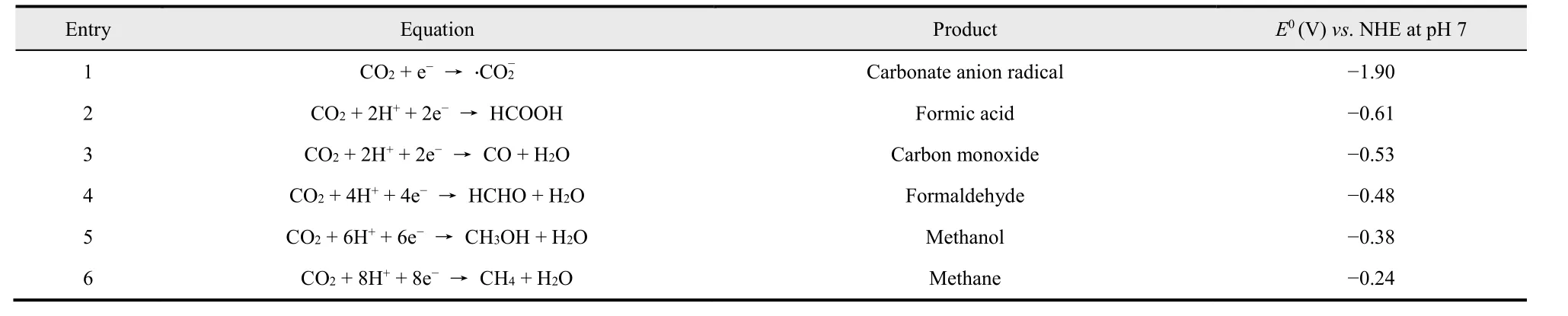
Table 2 Electrochemical reactions involved in CO2 reduction with water and their corresponding reduction potential E0 106.
The basic requirement of photocatalytic CO2reduction in water medium is that the maximum value of VB of the working photocatalyst must be less than the oxidation potential of water,while the minimum value of CB must be higher than the reduction potential of CO2to obtain the reduced product190.Equipped with controllable bulk and surface components, metal oxides have grasped their opportunity in modifying the photoexcitation and CO2activation process, leading to the enhanced conversion efficiency and selectivity. Among them,perovskite oxide materials have a good prospect in photocatalytic CO2because of their unique crystal structure (i.e.the crystallographic system deferring to the radius of metal atoms, two kinds of metal ions can be adjusted by defect engineering) and physicochemical properties (the bottom of the conduction band suitable for CO2reduction, high carrier mobility), as is shown in Fig. 8a169. The photocatalytic reduction of CO2by perovskite oxide involves several key steps, as shown in Fig. 8b191.
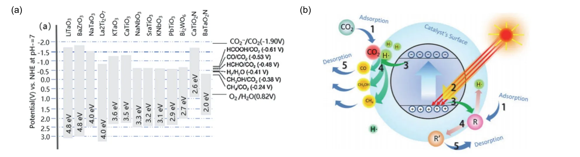
Fig. 8 (a) Band structures for a selection of perovskite oxides and oxynitrides and the corresponding redox potentials involved in photocatalytic CO2 reduction 169. Reproduced with permission from American Chemical Society. (b) Mechanism illustration of the photocatalytic CO2 reduction process 191. Reproduced with permission from Elsevier.

Fig. 9 (a) The FTIR spectra of gaseous feed, and products of CO2 +CH4 photocatalysis after 4 h visible irradiation on BZ11 (the powders containing BiFeO3 : ZnO with 1 : 1) sample. (b) The possible reaction mechanism of C1 products from CO2 reduction 52. Reproduced with permission from Elsevier.
Step 1: Adsorption of CO2molecules on the surface of the perovskite through two steps (physical adsorption driven by Van der Waals force and chemical adsorption driven by inter-atomic forces);
Step 2: Electrons in perovskite excited by the photons leading to the formation electron-hole carrier pairs;
Step 3: Photoexcited electron-hole pairs’ separation and migrating to the surface of the catalyst;
Step 4: The redox reaction start-up while reactants come into contact with the carriers;
Step 5: The desorption of reaction products from the surface.
Among them, steps 2 and 3 restrain the recombination of charge, which provides a guarantee for photocatalysis. Rational design like heterojunction and loading co-catalysts to suppress the recombination of charge pairs is of significant importance for improving the photocatalytic ability53,192. It is apparent that as tremendous amounts of electrons are required to drive the reaction to those stable products, thermodynamically stable products will not be kinetically favored193.
The FTIR spectra (Fig. 9a) indicated strong interaction of CO2evidenced from IR spectrum in the 2300–2500 cm−1and 3500–3800 cm−1region, while the peaks at 2800–3300 cm−1and 1200–1400 cm−1stemmed from the CH452. It can be corroborated (Fig.9a) that the new peaks, which were observed at 1300–1900 cm−1and 2600–3000 cm−1, were assigned to the functional groups of hydrocarbons and carbonyl compounds like CO, CH4, HCOOH,HCHO, and CH3OH as the main C1 products of the photocatalytic conversion of CO2after 4 h visible light irradiation194–196. In addition, Fig. 9b illustrates the predicted reaction mechanism of CO2reduction. As the CO2molecule is chemically absorbed on the perovskite, the O―C―O angle is no longer maintained at the original value of 180° due to the effect of the perovskite surface atoms. Following this, the whole system will observe the minimum energy principle to decide the newly added position of H. In this regard, a series of products(i.e.alkanes, carboxylic acids, aldehydes, and alcohols) that can be formed is determined by the varied semiconductors. Thus, it has ignited a wide range of interests to explore the relationship between the kind of perovskite between the main products and the index of selectivity (the amount of main products/the amount of the whole products), which is generally used to demonstrate the efficiency of obtaining the expected products. As such, Table 1 gives a summary of the main products. From the point view of environment, the photocatalytic CO2conversion not only is a green solution for clean and high-energy-density carbon fuels,but also gives the CO2a great opportunity to serve as a precious feedstock for sustainable energy production52. Accordingly, the different chemical composition and structure of perovskite oxide exhibits distinct activities. Structure-activity relationship ignites a wide range of interests. The photocatalytic reduction of CO2by H2O is one of promising technologies197, which can not only reduce the concentration of CO2, but also generate energy.However, it requires that the maximum value of valance band of the working photocatalyst be less than the reduction potential of water, and the minimum value of conduction band must be higher than the reduction potential of CO2in order to get the expected products198and the main products are HCOOH,HCHO, CH3OH and CH452,150,178–182,199,200.

Table 3 Summary of perovskite oxide based materials for photocatalytic water splitting.
Defect engineering plays a significant role in improving the catalytic efficiency of perovskite oxide, of which the performance can be altered by A/B site doping for modifying the photocatalytic performance of perovskite oxides, enhancing light absorption, charge transformations and subtle variations in metal cation coordination.
A carbon-doped NaTaO3photocatalyst exhibited a changing bandgap that was linked to the annealing temperature as shown in Fig. 10a115. It was clear that when the samples were annealed at 650 °C, the conduction band and Fermi energy were at the most negative potential level, which meant a more powerful force to start the CO2reduction115. In 2018, Wanget al.gave an in-depth research of La/Cr doping to CaTiO3, and the results reveal that the catalytic reaction showed the most promising efficiency with the perovskite doped with 5% La/Cr201. Since the doping of Cr introduces a new spin-polarized valence band within the original band gap of CaTiO3and the peculiar hollow cube microstructures of CaTiO3considerably increases chance of light reflections (Fig. 10b) and improves activities in absorbing long wavelength of photons, hollow CaTiO3exhibits higher light absorption and better photocatalytic activity than solid CaTiO3under full wavelength (λ≥ 250 nm) and visible light (λ≥ 400 nm)201. Meanwhile, various methods have been found to improve the catalytic efficiency by doping. For example, BiFeO3, Ba,113Mn202, and Co117have been adopted as a dopant to the perovskite. Take SrTiO3for example, after doping with transition metal cations (i.e.Co2+, Fe2+) which have 3delectrons, strong electron donor/accepter interactions will be formed and result in much improved CO2adsorption and a high CH4production rate172. Though defect engineering can help perovskite oxides extend their light absorption range far into the visible region, care must be taken to exclude defected-induced energy trap sites on account of charge recombination. Thus, this highlights the significance of maintaining a balance regarding the control of defect engineering as it pertains to the performance of the perovskite oxide.

Fig. 10 (a) Band structure scheme for as-prepared NaTaO3-C photocatalyst and samples annealed from 500 °C to 700 °C 115.Reproduced with permission from Elsevier. (b) Schematic representations of light reflections and refractions in hollow CaTiO3 201. Reproduced with permission from Elsevier.

Fig. 11 (a) Ag2CrO4/Ag/BiFeO3@RGO heterojunction showing movement of charge carriers; Photocatalytic CO2 reduction under visible light.(b) Yield of CH4. (c) Yield of CO. The band energy schematic diagram of BiFeO3 and ZnO 203. Reproduced with permission from Elsevier.(d) Before contact, and (e) after making p-n heterojunction along with the mechanism of visible light induced photoreduction of CO2 52.Reproduced with permission from Elsevier.
Furthermore, due to deep valence band composed of O 2porbitals, perovskite oxides can naturally drive oxygen evolution reactions. Interfacial heterojunctions with other semiconductors or organic sensitizers afford highly efficient CO2photoreduction through fast interfacial charge transfer processes and an extended visible light response. Heterojunction engineering can effectively suppress the recombination of photoinduced charges carriers. Moreover, the Z-scheme heterostructure is able to maintain the pristine redox ability without the sacrifice from recombination during the transfer. A Z-scheme Ag2CrO4/Ag/BiFeO3@RGO composite was proposed to enhance the photocatalytic ability as shown in Fig. 11a203. The protection of high potential CB and VB from BFO and ACO,respectively, by Ag through electron transfer and donation by surface plasmon resonance under visible light leads to facilitated CH4production. In addition, the present of RGO offers high surface area, which provides abundant active sites for adsorbing more CO2. Compared to the single Ag2CrO4and BiFeO3,Ag2CrO4/BiFeO3witnessed an improvement in the yield of both CO and CH4(Fig. 11b,c), which was further enhanced with the help of Ag and RGO203. As is shown in Fig. 6d,e, the Fermi level of ZnO is estimated to be ~0.8 eV below the bottom edge of conduction band due to the internal electric field, forcing the electrons and holes to flow in opposite directions52.Consequently, the photocatalytic activity of composites in the visible light range showed a substantial enhancement through the promoting effect of thep-njunction.
Morphology controlling has ignited a wave of tremendous research for improving the photocatalytic efficiency of perovskite oxides. Nanoscale morphologies of perovskite oxide always show fewer defects, which result in more resistance against charge carrier recombination. What is more, nanoscale morphology in perovskite oxide nanomaterials also provides high surface area, which can provide more active sites for photocatalysis54. Qinet al.developed coralline-like LaCoO3perovskite by a facile citrate gel method coupled with a thermal treatment in air103. The typical low-magnification SEM image(Fig. 12a) shows nanosized spherical particles interconnected firmly with each other, constructing highly porous layered fragments103. The high-magnification SEM image (Fig. 12b)confirms the spherical nanoparticles in LaCoO3structure103. The coralline-like porous nanoarchitectures merit a high structural stability and high surface area for CO2adsorption (15 cm3·g−1),augmenting the activity for CO2reduction.
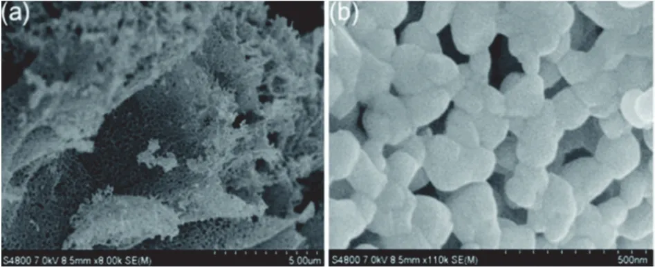
Fig. 12 (a) Low-magnification and (b) high-magnification SEM images of LaCoO3 sample 103. Reproduced with permission from Royal Society of Chemistry.
Benefiting from light effect, 3D ordered macroporous(3DOM) type perovskite also releases light harvesting efficiency. Wuet al.55successfully prepared the Pt nanoparticles-decorated three-dimensionally ordered macroporous perovskite-type SrTiO3(Ptn/3DOM-SrTiO3),which exhibited robust activity for CH4production (26.7 μmol·g−1·h−1). Fig. 13a–c shows SEM and TEM images of 3DOM SrTiO3structure55. The ordered macropores are interconnected by pore windows, while a number of mesopores on the wall of macropores are also observed, which augmenting the specific surface area of the reaction, hence increasing the surface active sites55.

Fig. 13 (a) SEM image of Pt2/3DOM-SrTiO3. (b, c) TEM and HRTEM images of 3DOM SrTiO3 55. Reproduced with permission from Elsevier.

Fig. 14 Schematic of photocatalytic CO2 reduction with H2O to CO and CH4 products over Ptn/3DOM-SrTiO3 catalysts 55.Reproduced with permission from Elsevier.
In combination with the photocatalytic mechanism (Fig. 14),the fascinating photocatalytic activity of Ptn/3DOM-SrTiO3results from the following synergies55: (1) The slow light effect of 3DOM photocatalysts boosts the light absorption. (2) Sr component serves as active sites for the adsorption and activation for CO2. (3) Decorated Pt NPs can trap and gather excited photoelectrons originated from SrTiO3for further reducing CO2into CH4.
5.2 Water splitting
Energy is the foundation of human activities and the important material basis of the national economy204–214.However, non-renewable fossil fuels such as coal and crude oil are still a major component of energy use215,216. The depletion of fossil fuels and the corresponding environmental problems(i.e.global warming167, acid rain217, air pollutants218brought on by the combustion of fossil fuels) have become one of the most serious challenges in the 21st century219,220. Thus, the development of an alternative sustainable and clean energy source has become a top priority. In this respect, hydrogen is considered as a promising candidate for next-generation energy carriers due to its large energy content of ~122 kJ·g−1and clean emission221–223. Compared with the environmentally unfriendly steam reforming of natural gas and the expensive electrolysis of water, photocatalytic water splitting is considered to be a promising approach for the production of H2due to its effective utilization of solar energy29,224–235. Since Fujishima and Honda94proposed the first photoelectrochemical water splitting system in 1972, photocatalytic water splitting has drawn immense attention and leading-edge achievements emerged in an endless stream to date, and the typical works are concluded in Table 3114,143,147,236–240.The basic steps in the process of photocatalytic water splitting on a semiconductor photocatalyst are shown in Fig. 15a241: (i) Light excitation. Water splitting is a chemical reaction with positive Gibbs free energy (ΔG0= +237 kJ·mol−1), so it needs enough energy to drive the uphill process.To illustrate this point, Fig. 15b shows a one-step excitation the energy band structure and energy level of photocatalytic water splitting. In order to drive the H2evolution and O2evolution reactions, the valence band maximum (VBM) should be more positive than 1.23 V (vs.normal hydrogen electrode, NHE),whereas the conduction band minimum (CBM) should be more negative than 0.00 V (vs. NHE). Thus, photocatalyst must have corresponding bandgap of at least 1.23 V to absorb enough energy for the water splitting reaction. (ii) Charge separation and transport. Under light stimulation, the electron-hole pairs separate and migrate to the surface active site. (iii) Surface chemical reaction. After transferring to the surface active sites,the photogenerated charges will be captured by H2O molecule followed by participating in H2evolution and O2evolution reactions.
Among multifarious photocatalyst materials (i.e.metal oxides(sulfides and nitrides)242, Bi-91and In-based materials,etc.),perovskite oxides ignited a wide range of interests due to their flexible compositions and electronic structures. As a representative perovskite photocatalyst, SrTiO3can achieve overall water splitting under ultraviolet radiation. The band gap and band edge potential energy of the perovskite crystal structure can be adjusted by doping with metals (Cr243, Zn244,etc.), and noble metals (Au, Ag,etc.). Hamet al.245developed the SrTiO3semiconductor doped with Al under a SrCl2flux, which obtained the high quantum efficiency of 30% at 360 nm and high activity in the overall water splitting reaction (Fig. 16a)245. The ameliorated performance was attributed to the flux treatment,which served as a medium to dissolve the SrTiO3particles and the Al2O3dopant, thus leading to higher crystallinity and giving an impetus to the Al doping of SrTiO3(Fig. 16b–d)245.
Morphological structure tuning strategy plays a functional role as well, the novel anisotropic 18-facet SrTiO3was fabricated by nanocrystal morphology tailoring method (Fig. 17)246.Specifically, the spatial charge separation and selective distribution of active sites on the facets of the 18-facet SrTiO3nanocrystals led to the fivefold increase of its apparent quantum efficiency in photocatalytic water splitting when compared to the pristine 6-facet SrTiO3.
In addition, the particle sizes of SrTiO3is also a thriving area of research. Compared with bulk SrTiO3, the 6.5 nm particles only possessed 10% of its photocatalytic activity, while the 30 nm SrTiO3particles can reach up to 65% (Fig. 18a)247. As such,the reduction of activity was inextricably associated with the quantum size effect. In such small size scale, space charge layers were not effective for separating electron-hole pairs, and the quantum size effect resulted in lower light absorption and water oxidation potentials. Thus, SrTiO3particles should be more than 30 nm to ensure the photocatalytic activity under UV light.
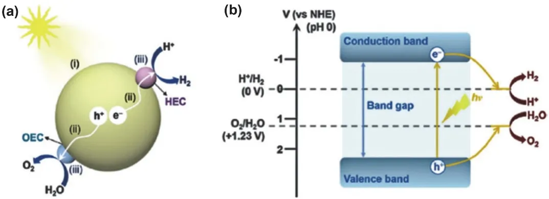
Fig. 15 (a) Basic principle of photocatalytic hydrogen and oxygen production via water splitting. (b) Energy band structure and energy level of photocatalytic decomposition of water 241. Reproduced with permission from Elsevier.

Fig. 16 (a) Water splitting activity of SrTiO3 photocatalysts. SEM images of SrTiO3 particles: (b) S TO(pristine), (c) STO(flux-Y), and(d) STO(flux-Al) 245. Reproduced with permission from Royal Society of Chemistry.

Fig. 17 The morphology engineering strategy for SrTiO3 nanocrystals. (a–c) The morphology of 6-facet SrTiO3 nanocrystals. (d) The structure of the(001) facet of SrTiO3. (e) The schematic description of changing SrTiO3 nanocrystals from 6-facet to 18-facet. (f–h) The morphology of 18-facet SrTiO3 nanocrystals. (i) The structure of the (001) facet of SrTiO3 246. Reproduced with permission from Royal Society of Chemistry.
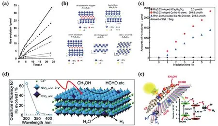
Fig. 18 (a) H2 (●) and O2 (○) evolution from bulk NiOSrTiO3 (solid line), 30 nm NiOSrTiO3 (dashed line), and 6.5 nm NiOSrTiO3 (dotted line) in 50 mL of water at pH = 7 under full spectrum irradiation (~26.3 mmol·L−1·cm–2 in the UV from 250 to 380 nm) 247. Reproduced with permission from American Chemical Society. (b) Crystal structures of layered perovskites 248. Reproduced with permission from Elsevier. (c) Time course of hydrogen evolution over (●) Rh(0.03)-doped Ca-Nb-O sheets, (■) Rh(0.03)-doped KCa2Nb3O10, and (▲) Rh(1.0 wt%)-loaded Ca-Nb-O sheet. (d) Crystal structure of Rh-doped calcium niobate nanosheet prepared by exfoliation of layered KCa2Nb3–xRhxO10−δ and photocatalytic reaction model in water/methanol system 116. Reproduced with permission from American Chemical Society. (e) Possible charge transfer in the CN/KCTO 2D–2D heterojunction photocatalysts and the corresponding mechanism for their excellent photocatalytic activity 249. Reproduced with permission from Royal Society of Chemistry.
Apart from bulk perovskite, recent research has witnessed rapid advances in layered perovskite due to its large specific surface area, ultrathin quality and charged nature. Generally,layered perovskite can be classified into following types: (100)(Aurivillius (AL) phase, Ruddlesden-Popper (RP) phase and Dion-Jacobson (DJ) phase), (110) and (111) types according to their different structures (Fig. 18b)250. Among all the pristine layered perovskites, RP and DJ phase perovskites exhibited great promise in photocatalytic water splitting, because they have a more flexible structure with replaceable interlaminar cations.The hydrogen production rate of H1.81Sr0.81Bi0.19Ta2O7in 4.76%methanol under UV light irradiation was extremely high at about 57670 μmol·g−1·h−1251. In another study, H2Ca4Ta2Nb4O20showed 8500 μmol·g−1·h−1hydrogen production rate in 10%methanol under incident light > 290 nm252. Although the layered perovskites have shown outstanding activities, further modification methods can facilitate in pushing the boundaries for garnering a better photocatalytic performance. Of which,metalion (i.e.Cr243, Zn244, Mo253,etc.) doping is a critical strategy to adjust the band gaps and promote charge separation.Yoheiet al.116obtained Rh-doped calcium niobate nanosheets,and the found that the doped KCa2Nb3O10nanosheets exhibited fascinating H2production rate (76960 μmol·g−1·h−1) (Fig. 18c),attributed to the electron trap RhO6units caused by Rh doping(Fig. 18d)116. Apart from that, nitrogen is a promising dopant as well, which is demonstrated by N-doped CsCa2Ta3O10nanosheets with a remarkable photocatalytic activity of 1660 μmol·g−1·h−1254and N doped Sr1.5Ba0.5Ta3O10nanosheets, which achieved the promising efficiency of 1303 μmol·g−1·h−1unexpectedly255. Heterogeneous composite construction has also become one of the hottest research horizons as their presence aids in the formation of a built-in electric field, thus leading to enhanced charge separation. In addition, the hybrid photocatalysts are usually propitious to be more stable and have a wide range of light absorption. Metal sulfides256and graphitic carbon nitride (g-C3N4)3,249are widely used to form hetero junctions with perovskites. g-C3N4has high conduction band position, visible light response, large specific surface area and favorable physical and chemical stability11,41,42,45,46,51. Thus,heterogeneous junctions of g-C3N4and layered perovskite possess commendable photocatalytic activity. The g-C3N4/KCa2Ta3O102D-2D nanosheet heterojunctions (Fig. 18e)fabricated by two-step wet chemistry synthetic method obtained intriguing H2evolution rate (4333 μmol·g−1·h−1), which was more than twice that of bare g-C3N4249. Under visible light irradiation, the photoinduced electrons in the conduction band of g-C3N4could be transferred to the KCa2Ta3O10conduction band through the close contact interface, and then Pt nanoparticles captured the accumulated electrons due to their high Fermi level.Meanwhile, the accumulated holes at g-C3N4valence band were captured by sacrificial agents (CH3OH). It is corroborated that 2D-2D heterojunctions not only boosted the solar spectrum utilization, but also formed a strong interfacial interaction for accelerating the charge separation, which is akin to a number of recent literature on the design of 2D/2D hybrid systems6,10.
In addition to aforementioned strategies, the restacking of layered perovskites will have a pronounced effect on their performance257–260. Compared to pristine layered perovskites,the restacked materials also possess large surface areas along the restacking directions due to their loose structure, which may provide more active sites for the adsorption of CO2molecule.Moreover, the stacking sequence can be used to locate the catalyst and photosensitizer directly in the interlayer space through a rapid layer-by-layer self-assembly process. Not only that, most of the layered perovskite photocatalysts were only able to work under UV light irradiation, which inevitably limited hydrogen production efficiency. In terms of practical applications, the stability and life of photocatalysts are of utmost significance. Lvet al.obtained a reduced graphene oxide encapsulated LaNiO3(LNO-RGO) composite through a facile self-assembly method. LaNiO3nanoparticles were encapsulated in reduced graphene oxide sheets, and this encapsulated structure made photocatalyst excellent long-term stability for 36 h (Fig.19a), which was 12 times higher than that of pure LaNiO3144.Fig. 19b shows the hydrogen evolution mechanism of LNORGO. Under irradiation, electrons flow rapidly to RGO along the Ni―C bond, leading to the separation of charges.Meanwhile, the meso-macroporous framework of crumpled nanoreactor provides active sites for the adsorption and diffusion of methanol molecules144. Apart from structural design, doping and changing the unstable ion valence state are widely used to enhance stability261. However, the current research development in this area is relatively slow and merits further attention in future studies.

Fig. 19 (a) Long-term stability test of LNO-RGO composite for 36 h. (b) Photocatalytic hydrogen production mechanism of LNO-RGO nanoreactor 144. Reproduced with permission from Elsevier.
5.3 Nitrogen fixation
Nitrogen, which is the main component of the earth’s atmosphere (~78%, volume fraction), is an indispensable element in the construction of life and vegetation262–270. As a pillar of various N-containing compounds, ammonia plays a critical role in agricultural fertilizer industry, industrial chemical and energy carrier. Although the N2fixation is an effective way of nitrogen utilization, the cleavage of the nonpolar N≡N triple bond requires to overcome a large bond energy of 941 kJ·mol−1and ionization potential271, thus leading to the chemically and biologically inert of N2and challenging N2fixation. Industrially,the traditional Haber-Bosch process produces most of NH3over the past centuries272. However, the process requires harsh reaction conditions at high temperature (300–500 °C) and high pressure (20–50 MPa). Meanwhile, it also gives rise to the power source consumption and greenhouse gas emission.
Since Schrauzer and Guth first reported that Fe-doped TiO2has the capability to convert N2into NH3under UV light irradiation in 1977273the photocatalytic synthesis of NH3has drawn immense attention for its energy-saving, high-efficiency,economy and environmentally friendly nature274–283.Subsequently, various photocatalyst like TiO2-based semiconductors284, g-C3N4285, ZnO286, BiOX287, WO3288as well as perovskite have been investigated in relation to N2fixation properties, and the typical researches in this field are summarized in Table 4121,146,289–292. It needs 6 electrons for N2to completely reduce into NH3and it is difficult for a semiconductor to possess the direct electron transfer (N2/N2−,−4.2 eVvs.NHE) and proton coupled electron transfer (N2/N2H,−3.2 eVvs.NHE). Therefore, searching for alternate lowerenergy routes to obtain chemical products is of rational importance. Fig. 20a shows the principle of photocatalytic nitrogen fixation in a semiconductor293. Under the light illumination, electrons are excited into the conduction band,keeping the holes within the valence band. The electrons and holes are then separated and diffused to the surface of the catalyst. Finally, electrons at CB react with nitrogen adsorbed at the active site to produce ammonia gas through multistep transfer of electrons and protons from water, while H2O molecule is oxidized to O2with holes. As shown in Fig. 20b,nitrogen reduction to ammonia can be carried out through two mechanisms: associative and dissociative294. In the dissociation mechanism, N≡N bond is broken before hydrogenation takes place, and single N-atoms are independently converted to NH3.In the associative alternating pathway, the two nitrogen centers remain bound to each other when the molecule is hydrogenated,and NH3can only be released when the final N―N bond breaks.In the associative distal pathway, hydrogenation may take placepreferably on farthest nitrogen on the other hand. In photocatalytic nitrogen fixation process, an optimum photocatalyst can improve charge carrier separations and extend the lifetimes of photo-generated charge carriers293,294. Hence, a wealth of studies focus on exploring different strategies including building orientation structure275, cocatalyst loading274,and designing heterostructured co-catalysts77,121to enhance photocatalytic N2fixation activities emerged in the past years.

Table 4 Summary of perovskite oxide based materials for photocatalytic N2 fixation.
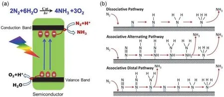
Fig. 20 (a) Schematic of photocatalytic N2 fixation to NH3 on a semiconductor based photocatalyst 293. Reproduced with permission from Elsevier. (b) Generic mechanisms for nitrogen reduction to ammonia on heterogeneous catalysts 294. Reproduced with permission from Elsevier.
A myriad of studies have elucidated to the potential of perovskite oxides as an effective photocatalyst. Benefiting from diverse composition of A, B sites and adjustable band gap, its absorption range and the catalytic efficiency can be significantly improved. Although doping is a widely adopted method to achieve better photocatalytic activity, the introduction of dopants will inevitably break crystallinity and bring forth the challenge of stability and carrier recombination. Zhanget al.146prepared Er-doped lanthanum cobaltite/attapulgite composites(LaCoO3: Er3+/ATP) through a sol-gel method. When the Er doping amount was 10% (w), the highest ammonia formation rate was 71.51 μmol·g−1·h−1, which was less prominent compared by other perovskite catalyst. The search for optimum dopants deserves a special degree of merit for further attention,be it now or in the near future. Zhouet al.275designed an oriented structure byin situbismuth reduction strategy (Fig.21a), leading to a regular distribution of crystallographic orientation in a polycrystalline sample. The oriented structure can construct a tightly connected interface and transfer channel for photo-excited carriers separation. Moreover, the quantum size effect elevated the bottom of the conduction band and boosted the reduction activities of photo-excited electrons.Moreover, the introduction of metal Bi serves as active sites and induces a preferential orientation, leading to a sufficiency high amount of NH3produced (86.0 μmol·g−1·h−1). Compounded with the preferred orientation and metal compounding strategy, these findings trigger ripples of high efficiency photo-catalysts design.Besides, noble metals are the most effective cocatalysts in the cocatalyst loading strategy. Xinget al.274synthesized Ag/KNbO3nanocomposite through the combination of hydrothermal and photo-deposition methods. The hydrothermal condition enhanced the bulk charge separation of KNbO3due to its high crystallinity, simultaneously, the Ag NPs decoration was designed as an electron trap to upgrade the surface separation of charge carriers. Meanwhile, researchers have elucidated on the existence of two different mechanisms in the Ag/KNbO3nanocomposite (Fig. 21b), alluding to the facilitation effect of Ag under simulated sunlight and visible light274.

Fig. 21 (a) Schematic illustration of the formation mechanism of Or-Bi/Bi2WO6 275. Reproduced with permission from Royal Society of Chemistry. (b) Possible mechanisms in Ag/KNbO3 composite under simulated sunlight and visible light 274. Reproduced with permission from American Chemical Society. (c) The photocatalytic mechanism of TiO2/SrTiO3/g-C3N4 heterojunctions under simulated sunlight irradiation.(d) The amount of nitrogen fixation per gram of sample under simulated sunlight irradiation 121. Reproduced with permission from Royal Society of Chemistry. (e) Charge transfer mechanism through the p-n junction in the MCeO2-BiFeO3 composite 273. Reproduced with permission from American Chemical Society. (f) Schematic illustration of the design and preparation of the as-fabricated BP hybrid photocatalyst 276. Reproduced with permission from American Chemical Society.
Apart from doping and adopting cocatalysts, the construction of heterojunctions obviously attracts wide interest. Fig. 21c shows the TiO2/SrTiO3/g-C3N4ternary heterojunction nanofibers synthesized by a combination of the electrospinning technique and gas-solid reaction121. Under sunlight irradiation,TiO2, SrTiO3, and g-C3N4generate photogenerated electrons and holes, respectively. The electrons of g-C3N4could transfer to TiO2through SrTiO3, and simultaneously SrTiO3itself could inject electrons into TiO2. The holes could transfer from TiO2and SrTiO3to g-C3N4in the same way. The gradient energyband heterojunction endowed by the TiO2/SrTiO3/g-C3N4nanofibers with highly cascade-driven charge-transfer properties was hypothesized to improve the photon-generated carrier separation. Meanwhile, the one-dimensional nanostructures provide a high specific surface area, which significantly increased the photocatalytic activity. Owing to the above advantages, TiO2/SrTiO3/g-C3N4nanofibers dramatically enhanced photocurrent response and decreased its transient photoluminescence lifetime in comparison with TiO2/g-C3N4nanofibers and SrTiO3/g-C3N4nanofibers, thus leading to excellent nitrogen fixation performance of 2192 μmol·L−1·g−1·h−1(Fig. 21d) as well as the structural stability121.Moreover, Mansinghetet al.273fabricated a rod-sheet (1D-2D)p-n heterojunction of MCeO2-BiFeO3(Fig. 21e) through a hydrothermal method. The impressive CeO2-BiFeO3p-nheterojunction photocatalyst exhibited an outstanding N2fixation efficiency (117.77 μmol·g−1·h−1), which was attributed to the formed oxygen vacancy and the built-in electric field brought by the CeO2-BiFeO3p-nheterojunction. Fascinatingly,surface modification is undoubtedly a significant strategy to realize the desired catalytic performance attributed to the introduction of active sites and the change of surface feature.Decorated by the organic matter of cyclized polyacrylonitrile (c-PAN) on the surface, the system showed a strong bonding state between c-PAN and Bi2WO6which was beneficial to form the unsaturated N sites which can be active sites to capture and activate dinitrogen (Fig. 21f). In this regard, the Bi2WO6/c-PAN composites achieved a superior nitrogen fixation performance of 160 μmol·g−1·h−1276.
Since the first report about photocatalytic nitrogen fixation in 1977277, the search for an effective photocatalyst has ignited a number of researchers to devote concerted efforts towards this field and the typical works about nitrogen fixation are concluded in Table 4. Undoubtedly, major strides have been made in increasing the photocatalytic efficiency due to the concerted efforts of these researchers, however, work on N2fixation using perovskite oxide photocatalysts are relatively scarce owing to the lack of effective active sites to cleave and fix N2. In conclusion, there is an urgent need to design perovskite oxide photocatalysts with copious and sustainable active sites to improve N2fixation efficiency and garner an in-depth understanding on the mechanisms in photocatalytic N2fixation.
5.4 Photocatalytic degradation
With the rapid development of industry in food processing,cosmetics, textile dye and medical manufacturing field, the water contamination caused by organic dye pollutants is becoming a hard nut to crack in public health and ecological system23,24,207,295,296. These dyes are extremely stable and difficult to be degraded naturally after entering the environmental waters, which damages the ecological balance of water bodies. What is more, the dye released into the environment is toxic and carcinogenic, which will pose a great threat to the health of human beings and other creatures. For the past few years, conventional physical, chemical, and biological treatment methods (adsorption, ultrafiltration, chemical oxidation, coagulation, microbial degradation,etc.) have been frequently implemented in removing organic pollutants in waste water. In spite of this, there is an urgent need for more efficient,environmentally friendly and cheap technique to remove the highly toxic pollutants rapidly. Thus, photocatalysis technology has critically influenced academic dialogue and fascination297–306.
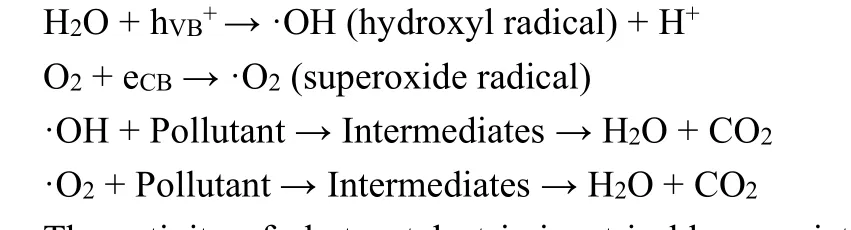
The basic mechanism of photocatalytic degradation is illustrated in Fig. 2213. At first, the photoinduced charges migrate to the photocatalyst surface under illumination, at the same time, the pollutants also transport from surroundings to the catalyst surface. The photoinduced charges react with oxygen and H2O molecules to produce the active species (OH*, O2−*,etc.), then the degradation of absorbed pollutant molecules occur at the surface of photocatalyst. Finally, the products (CO2, H2O)are desorbed. The reactions for the photocatalytic pollutant degradation can be summarized as follows.
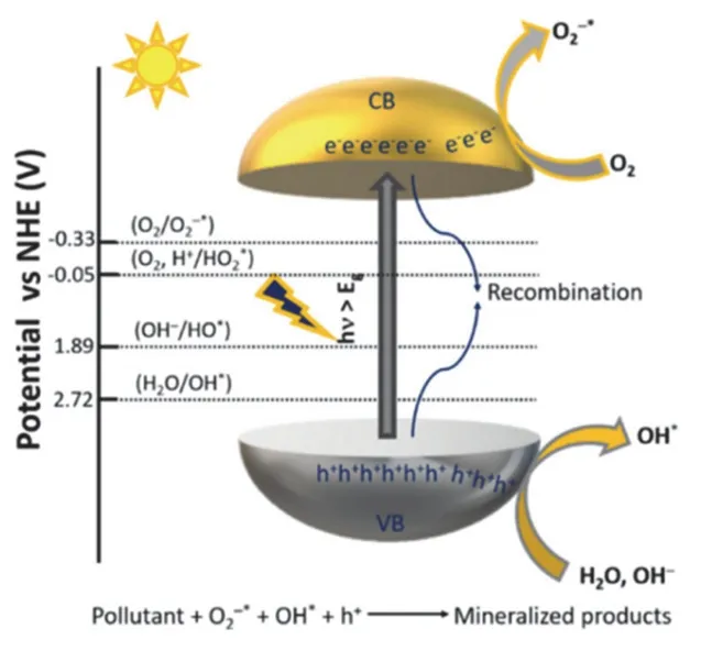
Fig. 22 Schematic of the general mechanism for photocatalytic pollutant degradation 13. Reproduced with permission from American Chemical Society.
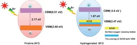
Fig. 23 Illustration of energy band for pristine BiFeO3 and hydrogenated BiFeO3 with oxygen vacancies 309.Reproduced with permission from Elsevier.
Photocatalyst +hυ→ hVB++ eCB
The activity of photocatalyst is inextricably associated with the recombination of photoinduced charges. The photogenerated electrons in perovskite effectively move from rare earth metal to transition metal due to the unique structure of perovskite, which proves that perovskite oxide is a robust candidate for the photocatalytic degradation25.
Various kinds of bare perovskite oxide (SiTiO3, LaFeO3,LaNiO3,etc.) have been widely explored for pollution degradation due to the overwhelming superiority of the excitation and transfer of photogenerated charge carriers in perovskite. Nevertheless, the further modification strategies,including defect engineering and heterostructure construction,drastically improve the efficiency of photocatalytic degradation through affecting the band gap structures and the suppression of electron-hole pair recombination4,23,26,27,87,90,92,97,307,308.
Oxygen vacancy construction is a feasible and general strategy for enhancing photocatalytic activity of perovskite oxides. The formation of surface oxygen vacancies can narrow the band gap of perovskite oxide photocatalyst, thus favoring the light absorption capability. Furthermore, oxygen vacancies can serve as trapping centers for photogenerated electrons, which suppress the recombination of electron-hole pairs as well as provide active sites for the adsorption of pollutant. High pressure hydrogenation process could introduce oxygen vacancies to BiFeO3, and the concentration of oxygen vacancies increased with the increasing hydrogenation temperature309. As shown in Fig. 23, the band gap for the pristine BiFeO3was 2.17 eV, while it decreased to 1.97 eV in the hydrogenated BFO309. The elevation of valence band could be explained from the overlap between VB edge and the delocalized surface impurity states imparted by oxygen vacancies. The existence of oxygen vacancies on BiFeO3surface also facilitates the adsorption of methyl orange.
NaNbO3with oxygen vacancies has been successfully synthesized through a well controllable solid-state reaction with NaBH4as a reducing agent by Yang and co-workers310. The reduced NaNbO3turned black, which was originated from the oxygen vacancies on the surface, and the concentration of oxygen vacancies could be easily tuned by the reaction time and temperature. The reduced NaNbO3with annealing temperature at 400 °C exhibited an impressive photo-degradation efficiency of methylene blue (Fig. 24)310. Itskvalue was about 1.5 times higher than that of pristine NaNbO3and increased by almost 2.4 times that of NaNbO3-400 °C sample. The improvement of photo-degradation efficiency was not only brought by the aforementioned narrower bandgap, but also associated with a larger specific surface area, which provided more active sites for methylene blue degradation and increased charge density provided by oxygen vacancies.
Apart from oxygen vacancies engineering, investigations on the heterostructure construction have dominated research in recent years. Benefiting from the unique traits including high conduction band position, visible light response, large specific surface area and favorable physical and chemical stability, g-C3N4is widely accepted to build heterostructure construction with perovskite oxides23,24,207,295,296.
The heterostructure construction between g-C3N4and perovskite oxides is propitious to form appropriate band positions and build close interfacial contact, which greatly extend the light absorption and accelerate the separation of photogenerated charges. Kumaret al.24utilized a polyacrylamide gel route to successfully synthesize sheet-like 2D CaTiO3nanoflakes, and prepared the heterojunction photocatalyst with CaTiO3nanoflakes and g-C3N4nanosheets(CTCN). Fascinatingly, the BET surface area of pure CaTiO3nanoflakes and g-C3N4nanosheets was 29.3 m2·g−1(Fig. 25a)and 41.0 m2·g−1(Fig. 25b), respectively. Upon hybridization, the area was boosted to 50.7 m2·g−1(Fig. 25c)24. The larger surface area offered more reactive site for the adsorption and degradation of rhodamine B. The photocatalytic mechanism of degradation of pollutants in CTCN photocatalyst was shown in Fig. 25d. The holes moved from VB of CaTiO3to VB of g-C3N4,while the electrons transfer to CB of CaTiO3from CB of g-C3N4due to the appropriate band positions and close interfacial contact. All of these reasons provided a crucial basis for the superior photocatalytic performance of 97% degradation of rhodamine B in 120 min under sunlight irradiation (Fig.25e)24. The research of Shi and his partners shed light on the introduction of N-defect into the g-C3N4framework by impregnation thermal method23. The irregular morphology of nitrogen-deficient g-C3N4led to loose structure and rich voids on the surface. As such, it greatly improved the specific surface area, which presented more surface active sites for the adsorption of pollutant molecules. Consequently, the upgraded photocatalytic degradation of tetracycline of nitrogen-deficient g-C3N4/KNbO3heterojunction photocatalyst was owing to the synergistic effect between the heterojunction and defect engineering.

Fig. 24 Reaction kinetics for NaNbO3 and reduced NaNbO3 in different temperature 310. Reproduced with permission from Royal Society of Chemistry.

Fig. 25 BET surface area plots for (a) g-C3N4, (b) CaTiO3 and (c) CTCN heterojunction. (d) Mechanism of degradation of pollutants under sunlight irradiation using the CTCN heterojunction photocatalyst. (e) Degradation percentage plots of RhB with sunlight irradiation after 120 min of irradiation 24. Reproduced with permission from Beilstein-Institut Zur Forderung der Chemischen Wissenschaften.
6 Theoretical calculation of perovskite oxide photocatalyst
Under the concerted efforts and synergy cooperation of numerous scientists, a myriad of studies have proved that perovskite oxide photocatalysts endow potential for efficient photocatalysis. A and B site cations in the perovskite lattice give a broader scope to tailor the structure and properties of photocatalyst, however, the conventional “trial and error”approach reduces the efficiency of developing novel materials.The theoretical calculation based on density functional theory(DFT) provides relevant insights into theoretical electronic band structures to uncover the structure-property relationship, which can be used to predict the photocatalytic performance and lays a good foundation for the rational development of effective new perovskite oxide photocatalyst311–313.
DFT calculations are commonly implemented in modeling to supplement the experimental results. Shtarevet al.314computed electronic band structure and density of states of barium bismuthate sample. As shown in Fig. 26a, the calculation results suggest that the bismuthate displays two bandgaps that correspond to lower-energy indirect (2.28 eV) and to higherenergy direct (2.36 eV) electronic transitions, which show good agreement with the experimental counterpart (2.26 and 2.43 eV)314. The density of states of the barium bismuthate sample(Fig. 26b) indicate that the valence band is formed only by oxygen-related orbitals, while the conduction band is a mixture of bismuth and oxygen orbitals. The above results reveal the energy band structure and electronic properties of Ba1.264(4)Bi1.981(4)O4.

Fig. 26 Electronic band structure (a) and density of states (b) of barium bismuthate sample 314.Reproduced with permission from Royal Society of Chemistry.
Jinet al.33demonstrated the 2D charge transportation properties of fluorinated Sr2TiO4. The band structure (Fig. 27a)suggests that there are large effective mass for charges in (001)di rection since the band dispersion along (001) direction (from point M to point A) in both conduction and valence band remains zero33. This result testifies that the charges in Sr2TiO4are constrained to move in the same AB plane. Fascinatingly, further analysis of density contour maps of Sr2TiO3F2(Fig. 27b)uncovers that TiO6breaks the coplanar settlement of VBM and CBM, thus leading to the separation of electrons and holes33.
As is well known, doping is a valid strategy to reduce the large band gap of perovskite oxide photocatalyst. Taking BaTiO3for example, Wanget al.315calculated the effect of replacing one O or Ti atom with non-metal elements of perovskite BaTiO3through spin-polarized DFT calculations. Fig. 28 manifests the relaxed local structure for non-metal elements (X = C, Si, N, P,S, Se, F, Cl, Br and I) doping configuration315. The distance of Ti―X bond is computed to be longer than the Ti―O bond(0.2002 nm) in pristine BaTiO3. The result shows that doping has a pronounced effect on the local structures, which brought by the different radius and electronegativity of the X relative to the O atom.
The result of total density of states (TDOS) and partial density of states (PDOS) suggests the changes of VBM and CBM (Fig.29)315. For instance, replacing an O atom with a C atom generates the C 2pstates right above the VBM and below the CBM of pure BaTiO3, which decreases the band gap to 1.93 eV.Profited from the contribution of S 3pstates, the VBM of Sdoped system is shifted to higher energy by 0.76 eV, resulting in the effective band gap of S-doped BaTiO3to be 2.55 eV.

Fig. 27 (a) Calculated band structures, total density of states, and partial density of states of constituent elements of Sr2TiO3F2, and Fermi level is marked by dotted orange line; (b) Density contour maps of Sr2TiO3F2 at VBM and CBM 33. Reproduced with permission from Elsevier.
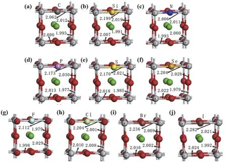
Fig. 28 Local structures of optimized configurations for (a) C-doped, (b) Si-doped, (c) N-doped, (d) P-doped, (e) S-doped, (f) Se-doped,(g) F-doped, (h) Cl-doped, (i) Br-doped and (j) I-doped BaTiO3 with X@O 315. Reproduced with permission from Elsevier.

Fig. 29 Total density of states (a) and projected density of states (b) for C-doped, Si-doped, N-doped, P-doped, S-doped and Se-doped systems. The vertical dashed line represents the top of the valence band of the bulk BaTiO3 as the reference level 315. Reproduced with permission from Elsevier.

Fig. 30 Schematic representation of the calculated VBM and CBM positions of X-doped BaTiO3 with respect to those of pristine BaTiO3 (a) with X@O and (b) with X@Ti 315. Reproduced with permission from Elsevier.
The doping at Ti site is also analyzed by computational calculations. The band edge positions of doping BaTiO3can be predicted as shown in Fig. 30315. From the point of view of water splitting, the replacements of O with C, S, Se and I have the led to improve water splitting activity under visible light.
7 Conclusion and prospects
Photocatalysis is an auspicious strategy to make use of solar energy to grapple with the energy and environmental problem that we are facing. In particular, perovskite oxides have ignited a wave of tremendous research as a burgeoning photocatalyst material. In this paper, the basic structure and synthesis methods of perovskite oxide including sol-gel method, chemical coprecipitation process, hydrothermal synthesis, solid state method and combustion synthesis methods are introduced. Their applications as photocatalytic materials in the field of photocatalysis, such as hydrogen production through water decomposition, reduction of CO2and immobilization of N2, are reviewed. Thanks to researchers’ concerted efforts, a plethora of modification techniques have been developed to increase the light absorption and photocatalytic performance, such as doping,surface decorations, interfacial engineering, defect engineering and band structure alignment. Nevertheless, with regard to the reduction of CO2and the immobilization of nitrogen, there is an urgent need for the design and development of high-efficiency catalysts to improve the selectivity and performance of the catalysts. Moreover, more in-depth studies should be focused on theoretical prediction and high throughput material genome,which demonstrates a broad prospect in the selection, design and development of new photocatalysts. In terms of practical application, ideal photocatalyst materials should have the merits of excellent photocatalytic activity, high stability, durability and low cost. In this condition, to find an efficient substitute for expensive noble metals and scarce rare-earth elements is of great significance. Additionally, TiO2photocatalysts still make up a major share of the commercial photocatalyst market, and the large-scale development of perovskite oxides is a new field.Mass production of high-quality perovskite photocatalyst by optimizing synthetic strategies is necessary in the journey for industrial up-scaled production. There is no doubt that due to the urgency of the global environment and energy, this direction will achieve more fruitful research results in the future with respect to perovskite oxide photocatalysts toward clean and green energy and environment.
杂志排行

物理化学学报的其它文章
- TiO2-Supported Single-Atom Catalysts for Photocatalytic Reactions
- Carboxyl-Functionalized Graphene for Highly Efficient H2-Evolution Activity of TiO2 Photocatalyst
- Controllable Synthesis of g-C3N4 Inverse Opal Photocatalysts for Superior Hydrogen Evolution
- 微波辅助快速制备2D/1D ZnIn2S4/TiO2 S 型异质结及其光催化制氢性能
- S-Scheme Heterojunction Photocatalyst for CO2 Photoreduction
- Fluorinated TiO2 Hollow Photocatalysts for Photocatalytic Applications