Experimental and numerical study on the flame root of premixed flame after a small size V-gutter
2021-07-05GONGFanHUANGYongWANGZongweiCHANGZhipengLIUZhu
GONG Fan,HUANG Yong,WANG Zongwei,CHANG Zhipeng,LIU Zhu
(1.Science and Technology on Physics Laboratory,Beijing 100076,China 2.School of Energy and Power Engineering,Beihang University,Beijing 100191,China)
Abstract:Flame stabilization in combustor is very important for the performance of combustors such as ramjet,turbojet or turbofan afterburners,and the flame stabilization mechanism is an important reference for the stability design of combustor.From the perspective of flame propagation and flame stabilization mechanism,the flame root is the key influencing factor.However,the traditional study focuses on larger size gutter,and there are few studies on small size gutter.The objective of this study is to investigate the flame root characteristics after a small V-gutter,and the research object is a two-dimensional lean methane premixed flame.In the experiment,the V-gutter size is 5 mm,and the Re number range is 126~315.The inlet velocity and equivalence ratio are adjusted respectively to obtain the variation of flame root characteristics with related parameters.When the inlet velocity is increased,the flame root moves downstream.When the equivalence ratio of inlet mixture is decreased,the flame root moves downstream.In the numerical simulation,the V-gutter size is 1mm and 2 mm,and the Re number range is 45~250.For the flame root after 1mm V-gutter,there is one flame root,and as the inlet velocity is raised,the flame root moves downstream.For the flame root after 2 mm V-gutter,there are two flame roots,and as the inlet velocity is raised,the flame roots move downstream and finally merge into one flame root until the flame blows out.For the small size V-gutter flame,when the flame is about to blow out,the flame root moves downstream.During this movement,the flame root can effectively sustain the flame propagation until the flame blowout finally occurs.The flame phenomenon found in this study can be used to support the establishment of a semi-empirical formula in the future.
Keywords: flame stabilization; V-gutter; flame root; small size; blowout
0 Introduction
Ground-based or aero-gas turbine engines,jet engine augmenters,ramjet or scramjet engine applications routinely incorporate bluff-body flame holders for primary or secondary combustion in high speed flows.In a propulsion system,flames are stabilized by using a flame holder with a recirculation zone[1].However,the flame is unstable when the engine closes to the lean blowout limit.In order to get the flame stabilized characteristics in the entire engine cycle,the lean blowout limit should be known accurately[2-3].
The bluff body is placed in a high-speed flow and produces a recirculation zone in the wake of bluff-body,allowing the combustion products to reside in this region for continuously igniting the oncoming flow[4].Research has been conducted for nearly six decades with the objective of understanding the underlying phenomena of bluff-body stabilized flames and there is an extensive body of literatures covering this subject[5].
The practical importance of the bluff-body stabilization process has given rise to a large number of theoretical and experimental studies.These studies aim to understand the physics of static stability in order to design the combustor to operate away from the unstable boundary.
Most of our present understanding of the flame stabilization process is due to the pioneering studies carried out by Longwell[6-7](Well Stirred Reactor model),Zukoski[8](Recirculation zone ignition model) and Lefebvre[9].Their work leads to the development of equations for predicting stability limit in terms of the bluff-body dimension,blockage ratio,pressure,temperature,velocity,and equivalence ratio of the incoming mixture.
These studies are based on two classical theories.One theory presumes that blowout occurs when the heat release of the reversed hot products in the recirculation zone is insufficient to heat the fresh mixture from the free stream,and the other one presumes that blowout occurs when the ignition time of unburned fresh mixture in the shear layer is less than the time required for the chemical reaction.Up to the present,the lean blowout models are proposed based on the theories above[10].These models consider the wake of the bluff-body flame as a whole,and the reactive flow field is not analyzed in detail.
The flame holder generates a flow field composed of boundary layers,separated shear layers,and a wake[11-12].From experimental chemical luminescence images[13],the flames exist in the shear layers and do not directly attach to the bluff-body.The interaction of flame and wall forces the flame to be anchored at a finite distance away from the flame holder,which is defined as the flame standoff distance.The flame propagates in the form of waves and is anchored near the flame holder,and the anchored location should be the position where the flame speed is equal to the flow velocity.The front points upstream of the flame sheets are the flame roots.
Kiel studied the bluff-body flames near the blowout and they asserted that the large von Karman vortex was the dominant drive in causing the flame extinction[14].But Khosla compared the blowout condition on bluff-body with and without von Karman vortex shedding[15].The results show that von Karman vortex shedding has no effect on the blowout condition,because the flame extinction occurs at the same equivalence ratio.
The flame root movements in both laminar and turbulent premixed flames have been a topic of investigation because of its relevance to the stabilization mechanism.Huang studied the anchoring point (i.e.flame root) experimentally and theoretically on Bunsen flame,and the experimental and theoretical results were in good agreement[16].Kedia and Ghoniem[17-18]studied the flame root movement on the small size perforated plate premixed flame,and their results showed that the flame was located totally after the recirculation zone,and the flame root moved downstream as the inlet velocity increased.The flame roots after small size V-gutter shows different characteristics from the flame after the large size V-gutter[19].
In this paper,the experimental and numerical study are conducted to investigate the operating parameters (the equivalence ratio and the inlet velocity) on the steady,lean premixed flame structure as well as the characteristics of the flow fields.The premixed flame after a small size V-gutter is performed.The movement of flame root is studied,and the flame structure and the flow field are analyzed.The characteristics of the small V-gutter flames are determined.
1 Experiment
1.1 Experimental facility
The V-gutter used in the experiment is made of stainless steel,as shown in Fig.1.The V-gutter width is 5 mm and its spread angle is 24 degree.The spanning width is 30 mm,which is same as the width of the test section.
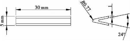
Fig.1 Schematic of the V-gutter flame holder.
A schematic diagram of the test facility used in the experimental investigation is shown in Fig.2.The basic system consists of an air supply at atmospheric pressure.Methane and air flows into a 350 mm long mixing duct separately to mix up,in which there are four perforated plates.Downstream of the mixing duct,there is the combustion chamber,which has a rectangular cross section of 30 mm×30 mm and a length of 320 mm.The V-gutter is placed in the test section,and is put on the centerline.Three side walls of the test section are quartz windows,which is accessible for the optical observation.
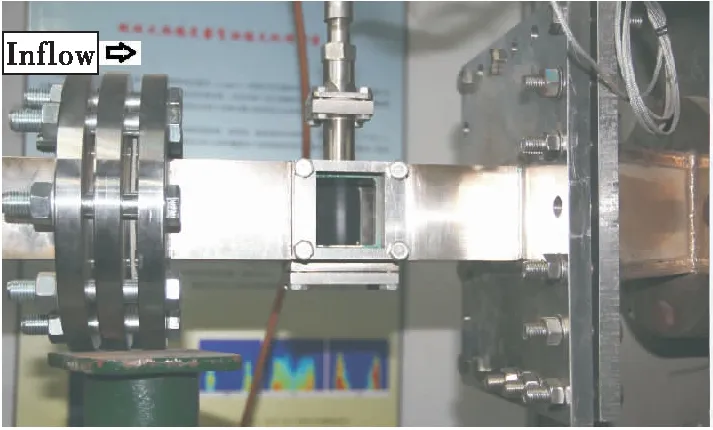
Fig.2 Experiment facility
1.2 Test conditions
The operating conditions are shown in table 1,a range of conditions are chosen to perform the required tests.The inlet velocity varies from 0.4 m/s to 1.0 m/s,and the equivalence ratio varies from 0.54 to 0.78.The Reynolds number range is between 126~315.
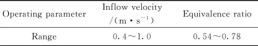
Tab.1 Operating conditions in experiment
The V-gutter flame is captured by a digital camera (SONY α33).Camera settings are shown in table 2.
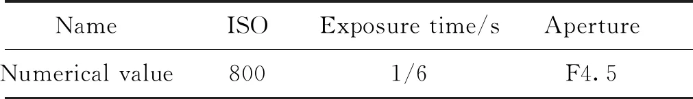
Tab.2 Camera parameters
2 Experimental results
The experimental flame after the V-gutter is shown in Fig.3.The direction of inlet flow is from right to left.The coordinate axis is put on the trailing edge and center line of the V-gutter.The V-gutter flame in Fig.3 is light blue.To emphasize the flame,the images are taken at the black background in the experiments,and the images are shown in Fig.4.
Fig.3 V-gutter flame in the duct
Fig.4 Determination of flame root
The method for determining the flame root is shown in Fig.4.At first,the photo of the flame is opened in PHOTOSHOP and zooms in.A border line can be achieved after running “color difference” order in the flame photo,as the white line in Fig.4 (b).The flame root is determined to be the point that is closest to the solid rim.
2.1 Inlet velocity
Fig.5 shows the flames at three different inlet velocities,and the equivalence ratio is 0.66.In Fig.5 (a),the inlet velocity is 0.5 m/s; In Fig.5(b),the inlet velocity is 0.6 m/s; In Fig.5(c),the inlet velocity is 0.7 m/s.The time-averaged flame surface is smooth.
Fig.5 V-gutter flames for φ=0.66
As the inlet velocity increases,the brightness of the flame sheet decreases.With the increase of inlet velocity,the angle between the flame and the flow direction decreases.That is because when the equivalence ratio is constant,the flame speed is constant,and the flame angle decreases as the flow velocity increases.In the Fig.5,when the inlet velocity is low,the distance between the two flame roots is close.
Fig.6 shows the movement of the flame roots with the variation of the inlet velocity when the equivalence ratio is kept constant.The round represents the data for equivalence ratio 0.58; the rectangle represents the data for equivalence ratio 0.62; the triangle represents the data for equivalence ratio 0.66.
Fig.6 Movement of the flame root with different flow velocities
When the equivalence ratio is constant,the flame root location onx-axisxb/Dincreases with the increase of inlet velocity.When the equivalence ratio is 0.58,the flame root location ony-axis is kept at 0.That indicates there is one flame root on the centerline.When the equivalence ratio is 0.62 and 0.66,the flame root location ony-axisyb/Dis increased.So as the velocity increases,one flame root is divided into two flames.
When the equivalence ratio is low,such as 0.58,there is one flame root on they-axis,as theyb/D=0.As the equivalence ratio is raised,the flame will move radially away from the centerline.As the inlet velocity is increased,the flame root is moving downstream.If the inlet velocity is continuously increased,the flame will blowout.
2.2 Equivalence ratio
Fig.7 shows the flames for three different equivalence ratios.As the equivalence ratio is increased,the brightness of the flame sheet increases,and the flame thickness increases.As the equivalence ratio is increased,the flame angle to the flow direction increases.When the equivalence ratio is raised,the flame speed raises,so that the flame angle increases.The flame thickness increases because the flame temperature increases with the increasing of equivalence ratio.
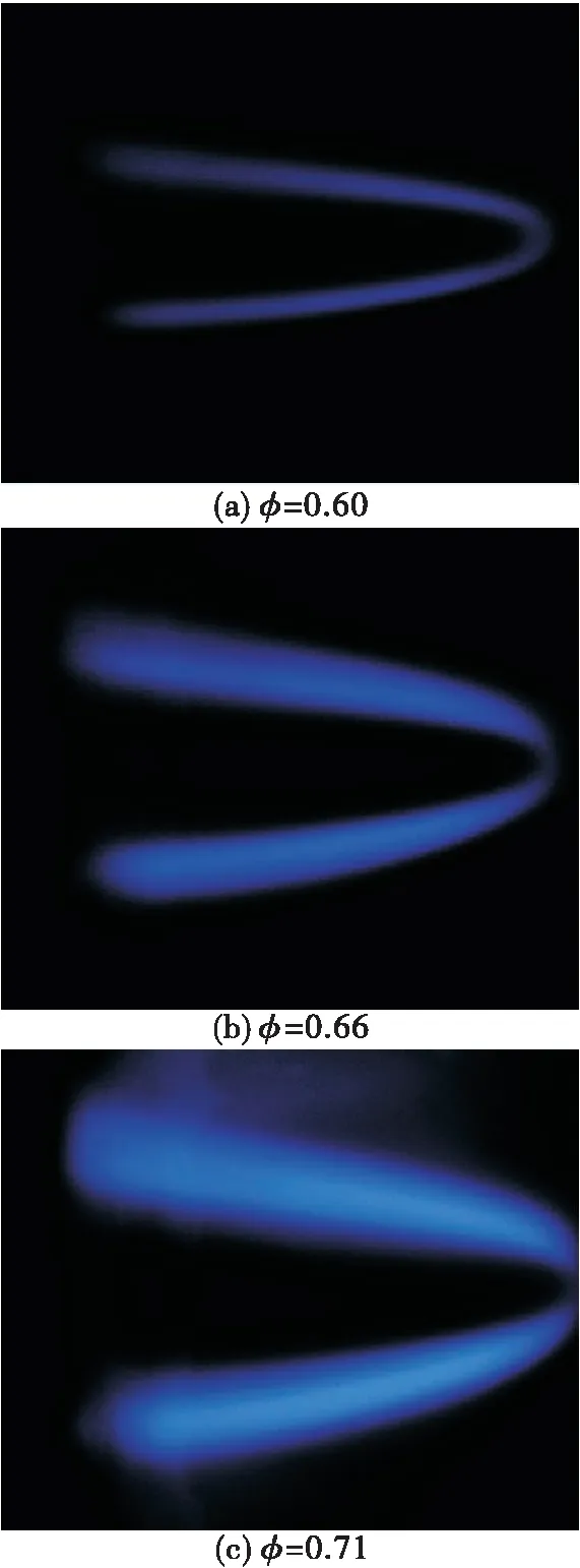
Fig.7 V-gutter flames for Uin=0.6 m/s
Fig.8 shows the movement of flame root with the variation of equivalence ratio when the inlet velocity is kept constant.The small square represents the data for inlet velocity 0.5 m/s; the round represents the data for inlet velocity 0.56 m/s; the rhombus represents the data for inlet velocity 0.6 m/s; the triangle represents the data for inlet velocity 0.66 m/s; the large rectangle represents the data for inlet velocity 0.7 m/s.
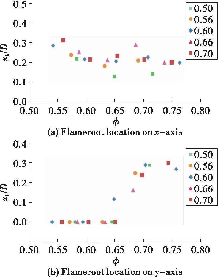
Fig.8 Movement of flame root with different equivalence ratios
When the inlet velocity is constant and the equivalence ratio increases,the flame root location onx-axisxb/Ddecreases and the flame root location ony-axis increases from 0.For the inlet velocity between 0.5 m/s to 0.7 m/s,when the equivalence ratio is below 0.65,there is one flame root due toyb/D=0.As the equivalence ratio decreases,the flame moves downstream.If the equivalence ratio continuously decreases,the flame will blowout.
3 Simulation
The flow fields after small size V-gutter for different inlet velocities are simulated by steady RANS solver.Commercial software FLUENT 14 is used for solving the mass,momentum,species,and energy conservation equations.The pressure based implicit steady second order upwind scheme,and the SIMPLE (Semi-Implicit Method for Pressure Linked Equations) algorithm are employed.The Laminar viscous model and Laminar Finite-Rate combustion model are adopted for laminar flow condition.To validate the adopted computation models,a perforated plate methane-air flame is simulated,and the results are compared with Kedia′s.As the perforated plate is to some extend like a bluff-body,so the laminar flowfield can be used for validation.
The governing equations for the mixture are shown below:
Continuity
(1)
Momentum
(2)
Energy:
(3)
Species:
(4)
WhereYkdenotes the mass fraction of species k;Rkis the generation or consumption rate of species k,hkis the enthalpy,andJkis the diffusion flux of species k;keffis the effective thermal conductivity of fluid;Shis the chemical heat release.
3.1 Validation
The computational domain for the perforated plate is the same as that in Ref.[17],and is shown in Fig.9.The black part in the computational domain is the plate body.The computational domain starts 13.2 mm upstream and ends 15 mm downstream of the upper-plate-wall.The thickness of the plate,d=1 mm and the diameter of the inlet hole,D=1 mm, see Fig.9(a).The flow conditions are:Tin=300 K,p=1.01 Pa,upstream velocity=0.8 m/s and the inlet premixed methane/air is atφ=0.75.Fig.9(b) shows the grid structure used in the present simulation.
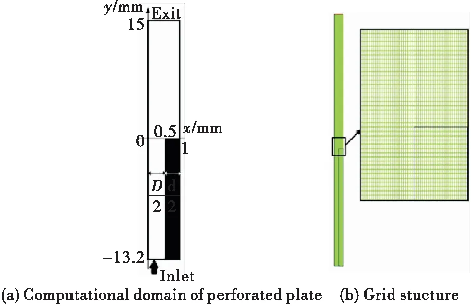
Fig.9 Computation domain for validation
The simulated local temperature contours are compared with Kedia’s and shown in Fig.10,and the circles represent the flame roots.Fig.10(a) is the results of present simulation and shows the flame root located atz/D=0.6,which agrees well with Kedia’s prediction as shown in Fig.10(b) (the flame root is located at aroundz/D=0.62).In Ref.[17],a detailed chemical kinetics mechanism with 20 species and 79 reactions for a methane-air mixture is used,while a one-step chemical kinetics mechanism is used in this simulation.From the results in Fig.10,it is concluded that the flame root location can be captured by one-step chemical kinetics mechanism.
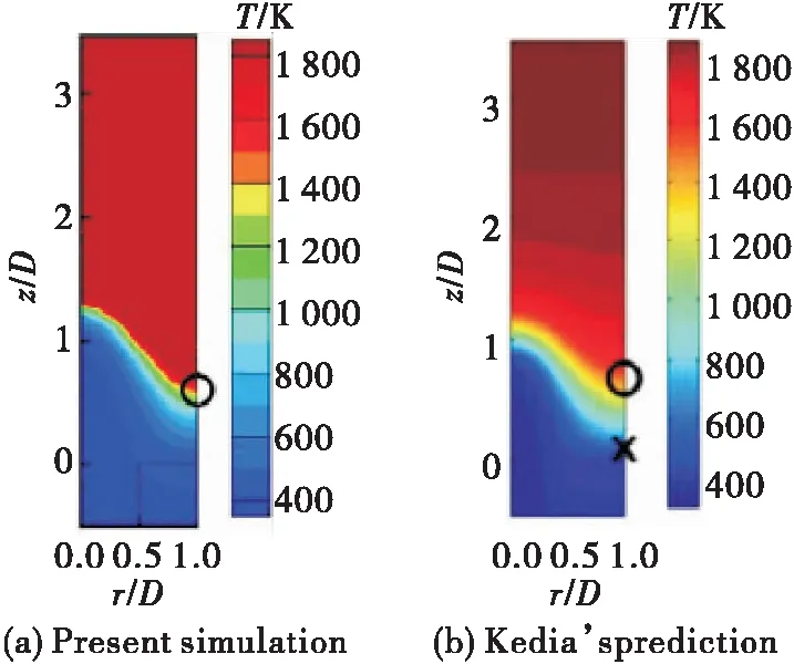
Fig.10 Comparison of temperature contours
3.2 Computational conditions
The different bluff-bodies studied in this paper are closed V-gutters placed in rectangular (2D) passages.The typical configuration is shown as Fig.11.
Fig.11(a) shows the closed V-gutter.The width and length of the V-gutter isDand 2D,respectively.Two V-gutters with different widths are studied including 1mm and 2 mm.The blockage ratios of the V-gutter are kept the same as 0.1.Fig.11(b) shows a closed V-gutter placed in a 2Dpassage.The computational domain starts 5Dupstream and ends 40Ddownstream of the trailing edge of the V-gutter.The upper and lower walls are 5Dfrom the center line.
Fig.12 shows the computational meshes forD=1 mm.Dense triangle grids are used around and inside V-gutters and square grids are used for the remained region.The grids around the V-gutter are small enough in order to obtain the detailed flow structure and the accurate flame root location.The grid points for 1 mm V-gutter is 13 122,and the grid points for 2 mm V-gutter is 18 854.
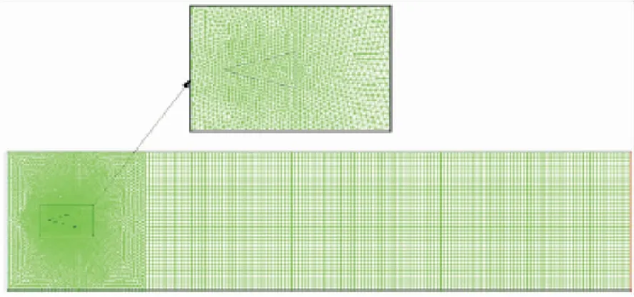
Fig.12 Grid structure used in simulations for D=1 mm.
The simulation is performed with the premixed mixture of methane and air.The inlet and outlet pressures are at atmosphere conditions,and the inlet temperature is 300 K.The equivalence ratio is kept at 0.8.The coupling effect of heat transferring to the V-gutter has been considered in computations.The thermal conductivity of the V-gutter is 1.5 W/ (m·K).The operation conditions of the simulation cases are shown in Tab.3.
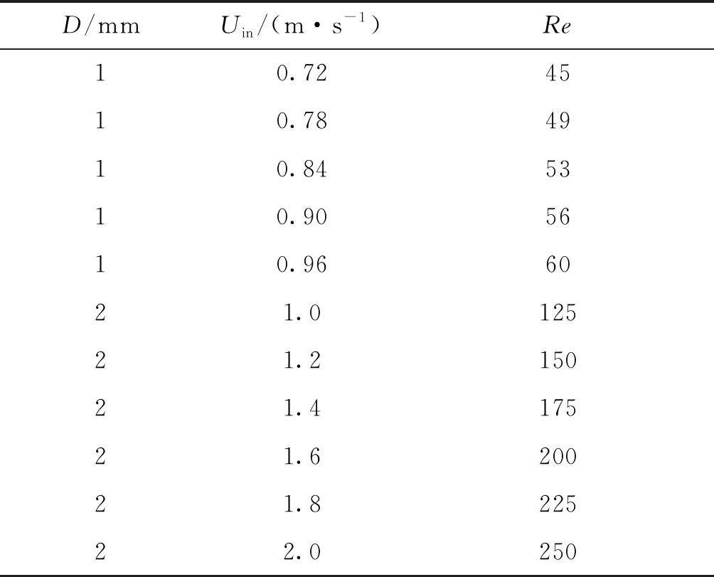
Tab.3 Operation conditions of simulation cases
4 Computational results
The reactive flow fields are shown in the following figures,the black part is the V-gutter’s trailing body.In these figures,the grey contour represents the methane reaction rate; the solid lines represent the iso-lines of axial velocities; the dashed lines represent the temperatures iso-lines.The dash-dot-dot lines represent the iso-lines of fuel mass fraction.It is considered that the low velocity region and the high temperature are two fundamental conditions for flame roots,so here the flame root is defined as the front point of the isoline of 1 400 K temperature (i.e.flammable temperature[19]).The flame root is the front point of the flame sheet,and is represented by a circle.
4.1 1 mm V-gutter flame
Fig.13 shows the constant-axial velocity lines,isotherms,kerosene mass fraction iso-lines and the reaction rate contours near the flame root at different inlet velocities forD=1 mm.
In Fig.13,there is one constant-axial velocity lines of 0 m/s and four isotherms of 600 K,1 000 K,1 400 K and 1 800 K.There are two methane mass fraction iso-lines of 0.044 and 0.000 01,which represents the maximum and minimum methane mass fraction,respectively,and encircle the main reaction zone.WhenD=1 mm,there is one flame root and the flame root is located on the centerline behind the V-gutter’s trailing.Fig.13 (a) shows the reactive flowfield forUin=0.78 m/s and there is no recirculation zone because the inlet velocity is too small.Fig.13 (b) shows the reactive flowfield forUin=0.84 m/s and the recirculation zone is just onset.Fig.13(c) clearly presents long recirculation zones forUin=0.96 m/s.
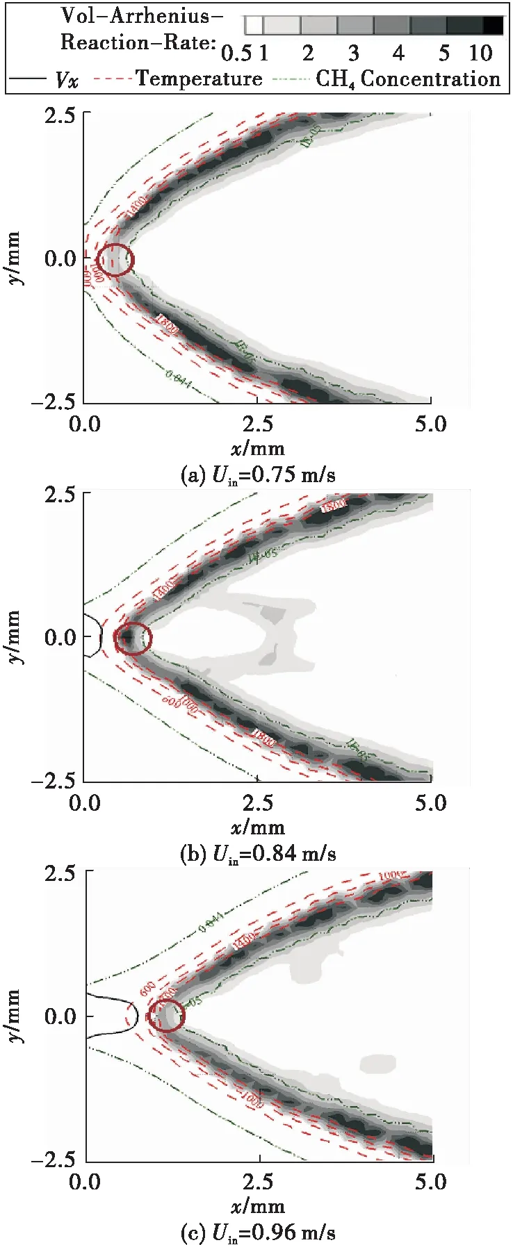
Fig.13 Reactive flow field for 1 mm V-gutter
Fig.14 shows the movement of the flame root after 1 mm V-gutter with the variation of the inlet velocity,and the equivalence ratio is 0.8.When the inlet velocity increases from 0.72~0.96 m/s,the flame root moves downstream in x-direction from 0.3~1.3D,and the location of the flame root in y-direction is kept at 0.The length of recirculation zone is increased from 0~1.1D.
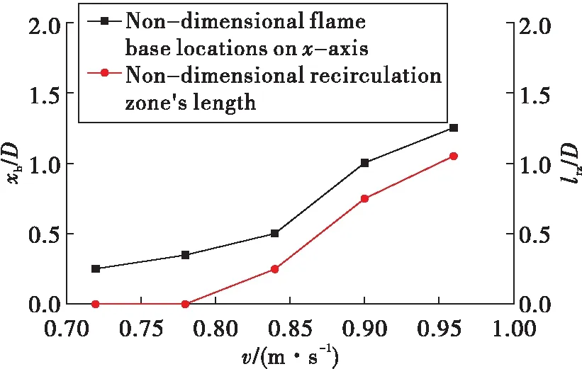
Fig.14 Movement of flame roots after 1mm V-gutter
As the inlet velocity increases,the flame moves downstream.The tendency of the flame roots’ variation with the inlet velocity in the simulation is same as that in the experiment.
4.2 2 mm V-gutter flame
Fig.15 shows the reactive flow fields for three different inlet velocities for the flames after 2 mm V-gutter.In Fig.15,the inlet velocity is 1.0 m/s,1.2 m/s and 1.6 m/s,respectively.
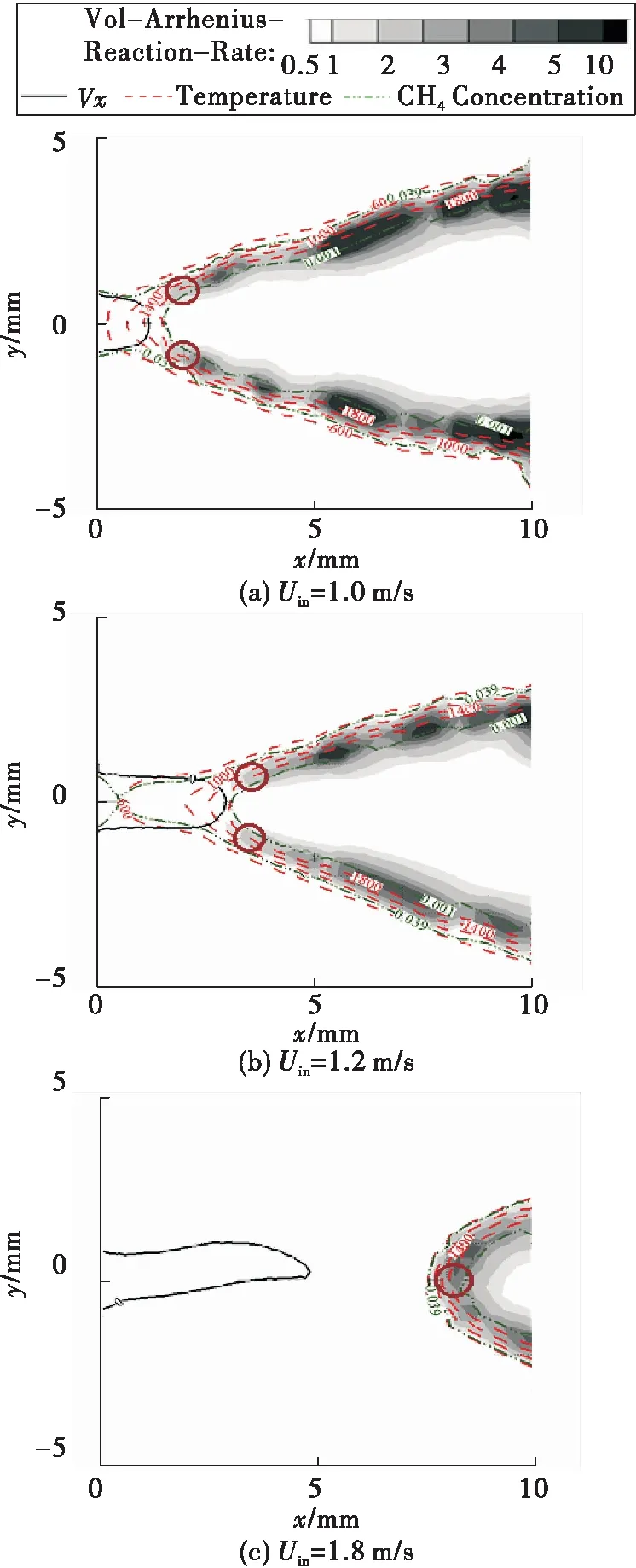
Fig.15 Reactive flow field for 2 mm V-gutter flames
In Fig.15,the width D=2 mm.Fig.15 (a) shows the reactive flowfield forUin=1.0 m/s,there are two flame roots and the flame roots are located after the V-gutter’s trailing.Fig.15(b) shows the reactive flowfield forUin=1.2 m/s,and the two flame roots move downstream.Fig.15(c) shows the reactive flowfield forUin=0.96 m/s,and the recirculation zone length is increased,and there is only one flame root.
Fig.16 shows the movement of the flame root after 2 mm V-gutter with the variation of the inlet velocity,the equivalence ratio is 0.8.When the inlet velocity increases from 1~2 m/s,the flame roots move downstream in x-direction from 0.8D~3.9D,and the location of the flame roots in y-direction is decreased from 0.48D~0D.The length of recirculation zone is increased from 0.7D~2.4D.
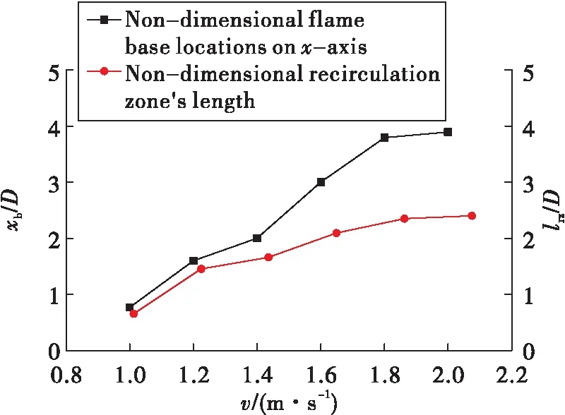
Fig.16 Movement of flame root after 2 mm V-gutter
The flow time can be considered as the ratio of the length of recirculation zone to the inlet velocity,tflow=LRZ/Uin.In the numerical cases,the range of the flow time is from 0 ms to 2.6 ms.The ignition delay time is larger than 10 ms[20],so that the ignition delay time is larger than flow time.Besides,the temperature in the recirculation zone is below 1 000 K,and even below 400 K,so the recirculation zone can’t heat the incoming flow.That is the reason why the flame root can’t exist in the shear layers of the recirculation zone.Furthermore,the length of recirculation zone is nearly same as the quench distance.The flame can only exist outside the quench distance.
5 Conclusions
The studies on the flame after the small size V-gutter placed in a two-dimensional passage are performed experimentally and numerically.The inlet mixture is the premixed methane and air.In the experiment,the V-gutter size is 5 mm,and theRerange is 126~315.In the numerical simulations,the V-gutter sizes are 1mm and 2mm,and theRerange is 45~250.
In experiments,the effect of the inlet velocity and equivalence ratio on the flame structures and flow fields are investigated.As the inlet velocity isincreased,the flame angle to the flow direction decreases.When the inlet velocity is increased,the flame root moves downstream.As the equivalence ratio of inlet mixture is decreased,the flame angle to the flow direction decreases.When the equivalence ratio is decreased,the flame root moves downstream.When the equivalence ratio is low,there is one flame root; when the equivalence ratio is increased,there are two flame roots.
In numerical simulations,for the flame root after 1 mm V-gutter,there is one flame root,and as the inlet velocity is raised,the flame root moves downstream.For the flame root after 2 mm V-gutter,there are two flame roots,and as the inlet velocity is raised,the flame roots move downstream.The two flame roots become one as the flame near blowout.
For the flame after the small size V-gutter,when the flame approaches the blowout,the flame roots move downstream.As the flame root moves downstream,the flame root can’t sustain the flame propagation,and then the flame blowout will occur.The phenomenon can be used for the semi-empirical formula establishment in the future.
