基于CFD的植物工厂圆形锯齿状水冷LED灯管降温效果模拟
2021-06-30程瑞锋仝宇欣
方 慧,程瑞锋,仝宇欣,李 琨
基于CFD的植物工厂圆形锯齿状水冷LED灯管降温效果模拟
方 慧,程瑞锋,仝宇欣,李 琨※
(1. 中国农业科学院农业环境与可持续发展研究所,北京 100081;2. 农业农村部设施农业节能与废弃物处理重点实验室,北京 100081)
为及时将LED灯管芯片产生的热量传导出去,提升LED灯的性能,延长其使用寿命,设计了一种圆形锯齿状水冷LED灯管,并通过计算流体力学(Computational Fluid Dynamics, CFD)软件构建水冷LED灯管模型,对其降温效果进行研究。在模型中将LED灯珠芯片设置为内热源,热流密度根据灯珠的数量和电光转化效率计算,其值为1.7×10⁷W/m3。验证试验表明,模拟值与实测值吻合较好,最大误差为16.4%,构建的CFD模型能准确模拟灯管各结构的温度分布。利用验证的模型模拟不同水流速度对水冷LED灯管温度分布及水流压降的影响。结果表明:不同流速下水冷LED灯管的金属散热灯罩、灯珠芯片和水流的温度分布比较均匀,表明该灯管的结构设计合理,灯珠芯片释放的热量能很快传导到水流中并被带走;当灯管入口水流速度从0.10 m/s增加到0.25 m/s时,进出水温差从1.4 ℃下降到0.5 ℃。因此,在对水冷LED灯管进行串联时,可根据进水温度和环境温度的差来计算可串接灯管数量;入口水流速度的增加亦会增加水流阻力,根据模拟得到灯管进出水压差计算出灯管对水流的阻力系数为2.2,为水泵选型提供了依据。
温度;计算流体力学;植物工厂;人工光源;模拟;水流速度
0 引 言
人工光植物工厂是一种通过对设施内温度、湿度、光照、CO2浓度以及营养液等环境要素进行高精度自动控制,实现作物周年连续生产的高效农业系统[1]。随着世界人口、资源、环境问题的日益突出,植物工厂以传统农业无法比拟的优势,受到世界各国的广泛重视,相关技术迅速发展成熟,在不同领域得到了广泛应用[2-4]。中国累计推广面积达700多万平方米[1]。
植物工厂一般采用空调进行光/暗期变温控制[5-9],空调热负荷的85%以上来自于人工光源在植物光期散发的热量。尽管光源采用具有冷光源之称的LED,仍有70%以上的电能转化成热量[10],导致空调能耗占植物工厂总能耗的15%~25%[11]。如果未及时将这部分热量带走,热量的急剧积累会导致LED芯片温度的迅速上升,引起发光效率下降、波长漂移、器件失效及寿命急剧减短等一系列问题[12-13]。Nadarajah等研究表明,当光源温度从38 ℃上升至55 ℃时,其寿命由约50 000 h骤降至10 000 h[14]。LED芯片产生的高温除损害元器件外,也不利于蔬菜生产。在热辐射和热对流作用下,这些热量使光源下方植物栽培区温度上升,降低植物水分和养分利用效率[15-16]、降低光合速率、增强暗呼吸[17]、减少矿物质吸收[18-20]、增加抽薹率、叶片烧心[21]、叶柄变色[22]、叶片变苦[23]、口感下降[24]及叶球松散[25]等症状,对植物工厂生产和经营造成明显的负面影响。
植物工厂中通常采用强制空气冷却方式将光源热量带走。以目前主流的LED植物工厂为例,LED芯片工作中产生的热量先以热传导的方式转移至散热片上,而后以对流与辐射形式将热量传导至空气中,再经植物工厂内气流运动输送至空调进行调温处理。但该过程热量转移较为缓慢,尤其是在密集的栽培系统及蔬菜植株遮挡情况下,正常的空气流动受阻,无风区域极易发生热量积聚。为解决上述问题,有学者研究将通气管置于栽培区植物上方[26-27]和下方[28],实现栽培区内垂直方向上的气流扰动,以减少无风区域;Moon等采用降温-加热-通风系统联合调控的混合控制策略减少植物工厂栽培架层间及不同区域的环境差异,提高其均匀性[29];李琨等提出了根际通风方法,使植物工厂环境空气流经水培系统中营养液面与栽培板之间的空气层后经植物冠层下部吹至栽培区,实现高效的通风[30]。上述研究成果虽然能够加强通风效能,缓解局部温度上升对蔬菜的负面影响,在一定程度上提高光源强制空气冷却效果,但随着植物工厂规模的不断扩大,植物工厂内气流分布不均的状况愈发明显,局部环境均匀性和降温效率亟待进一步提高。
液冷直接对光源进行冷却是一种效率更高的降温方式。液体具有更高的导热系数与定压比热容,能大幅度降低换热环节热阻,提高冷却效率,其散热效果比风冷方式要强20倍以上[31]。目前大功率LED光源水冷系统研究主要集中在新型流道、换热器结构与翅片设计方面[32],较少研究其在实际应用环境下的性能表现。刘晓英等设计了水冷式植物工厂LED面光源及散热系统,并对其运行性能进行了测试,发现较无水冷散热装置的散热器温度低5.3~19.3 ℃[33],该研究仅测定了温度变化情况,并未对其散热器设计与运行关键参数进行探索。尽管目前针对水冷散热系统结构及模拟研究较为深入,也有部分研究测试了水冷系统的实际降温性能,但仍然缺乏以植物工厂实际生产应用为目标的光源水冷散热系统解决方案及其关键参数对散热性能的影响研究。
本研究针对植物工厂大规模应用设计了一种圆形锯齿状水冷LED灯管,基于Fluent软件对灯管装置热传导、水流压降进行模拟分析,探究了同一进水温度不同流速下灯管装置降温性能及水流的阻力系数,以期为LED补光灯在大型植物工厂中的研究及应用提供理论依据。
1 数值模拟
1.1 模型参数及运行原理
基于市售常规LED植物灯管外形规格参数,设计开发了一种通用型圆形锯齿状水冷LED灯管,其结构如图1所示,由水流管路、电源接口、密封盖、密封圈、固定丝扣、金属散热管道、灯罩、LED芯片、散热铝板等构成。LED发光芯片固定于散热铝板上,铝板嵌入到管道一侧的凹槽中,与水管侧面紧密贴合。为增大水流与管路的接触面积,管路内部设计为圆形锯齿状凹凸面。
1.水流管路 2.电源接口 3.密封盖 4.密封圈 5.固定丝扣 6.金属散热管道 7.灯罩 8.LED芯片 9.散热铝板
1.Water pipe 2.Power connection 3.Sealing cover 4.Sealing ring 5.Fixing screw thread 6.Metal heat dissipation pipe 7.Lamp shade 8.LED chip 9.Heat dissipation plate
图1 圆形锯齿状水冷LED灯管试验装置模型
Fig.1 Test device model of circular serrated water-cooled LED
1.2 模拟方程
水冷LED灯管中LED芯片为散热源,其释放出的热量以下述3种途径被带走:1)对流换热:一部分热量以对流的形式传递到灯罩的空腔中,灯罩通过与空腔和环境中的气体进行对流换热,将热量释放到室外环境中;2)热辐射:芯片为高温固体,芯片和灯罩之间存在温差,导致芯片一部分热量以热辐射的形式传递到灯罩,最终释放到环境中;3)热传导:芯片的大部分热量直接传导到散热板,再通过流动的水将热量带走。在本模拟中启动能量项,选择-湍流模型[34],相关控制方程为
1)动量守恒方程
方向上:
方向上:
方向上:
式中为水流的密度,kg/m3;为水的动力黏性系数;为时间,s;为速度矢量;、、分别为流体质点速度在,,方向上的分量,m/s;S、S、S为源项,kg·m/s;为压力,Pa。
2)能量守恒方程
式中为温度,℃;为各材料的导热系数,W/(m·℃);p为各材料的比热容,J/(kg·K);S为芯片散热源项,W/m3。
1.3 网格划分与边界条件
为简化结构网格划分,管路与散热板间的缝隙忽略不计,考虑为一个整体。将构建的水冷LED灯管模型输入到ANSYS Meshing模块中,利用Proximity and Curvature方法对几何体进行网格划分,并对LED灯株芯片和管道近壁面网格进行加密处理,共生成1 162 800个网格,220 881个节点,网格最小尺寸为2 mm,利用skewness计算出网格最大偏斜度为0.84,最小偏斜度为1.3×10⁻¹⁰,平均值为0.25,网格质量可用于案例模拟分析。
在边界条件设置中将管路的一端设置为进水口(Velocity-inlet),另一端为设置压力出口(Pressure-outlet),水流管道设计的最大承载流量为6 kg/h,进水管道直径为4 mm,则进水口的最大流速为0.5 m/s。在建筑供暖中为满足暖气管中的气泡能被水流带走,因此设计流速一般为0.25 m/s[35]。在本试验中为得到最优水流速度,设置4个速度梯度,分别为0.1、0.15、0.2和0.25 m/s。管路外壳与散热板均为导热固体材料,LED灯珠芯片设置为热源。环境操作温度为植物工厂光期控制温度,设置为24 ℃。
1.3.1 进水温度计算
植物工厂光期环境温度和相对湿度分别按24 ℃和70%考虑,为保证水冷LED灯管无冷凝,则水流温度应高于露点温度,其计算式为[36]
(5)
式中=0.198 0,=0.001 7,=0.840 0,均为系数;t为露点温度,℃;t为干球温度,℃;RH为相对湿度,%。通过式(5)计算得到植物工厂露点温度为17 ℃,为保证灯管无结露,进水口水流温度应不低于露点温度,因此,在模型中将水流入口温度设置为17 ℃。
1.3.2 芯片热流密度计算
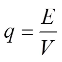
圆形锯齿状水冷LED灯管由300颗灯珠组成,灯珠均匀排布于散热板上,总电功率为60 W。根据Nelson的研究表明红色LED灯珠和蓝色LED灯珠的电光转化效率分别为32%和49%[37]。据此,灯珠芯片的热流密度计算式为
=(1−) (6)

式中为灯珠的电功率,W;为灯珠电光转化效率;为灯珠的热功率,W;为单个芯片的体积,m3;为单个芯片热流密度,W/m3。结合式(6)和(7),水冷LED灯管芯片的热流密度为1.7×107W/m3。
本试验模拟计算中所涉及的材料包括气体(空气)、液体(水)和固体(玻璃、铝),所有材料热物理属性如表1所示。

表1 材料热物理属性
1.4 计算方法
在Fluent中湍流模型选择标准-模型,近壁面采用“Enhanced wall treatment”壁面函数,考虑壁面作用和浮升力的作用,选择“Full buoyancy effects”,同时打开能量方程和重力项。动量、能量和黏性项都选用一阶迎风格式,以达到更快收敛。将能量项的松弛因子设置为10-6,其余项均设置为10-3以判断结果是否收敛。
1.5 模型验证
模型验证是检验数值模拟准确性的重要方式之一,相应的模型验证试验装置如图2所示,包括水箱、水泵、三通阀、节流阀、流量计和水冷LED灯管。试验用供水水泵(型号:WS123;工作电压12V;流量:8 L/min;扬程:3 m)与三通阀连接,三通阀的一端与流量计(型号:LZM-15ZT;测量范围:0.04~0.4 m3/h)连接,另一端与节流阀连接,通过流量计和节流阀控制流入水冷LED灯管的水流速度。测点布置:分别在水冷LED灯管的金属散热管侧面和玻璃灯罩侧面的中间位置及两端各布置1个温度测点,合计6个温度测点;在水流出、入口分别布置1个温度测点,合计2个测点。温度测量选用铜-康铜热电偶线,其测量精度为±0.2 ℃,所有数据通过HOBO数据采集仪(型号:UX120-014M)采集,采集时间间隔为1 min。
1.流量计 2.灯管 3.三通阀 4.节流阀 5.水泵 6.温度传感器
1.Flowmeter 2.Lamp 3.Three-way valve 4.Throttle valve 5.Water pump 6.Temperature sensor
图2 水冷LED灯管验证装置整体结构
Fig.2 Overall structure of water cooled LED validation device
2 结果与分析
2.1 试验验证
为验证数值模型,测试了进水温度24 ℃,流速0.2 m/s时的水冷LED灯管各结构的温度稳定实测值,并将实测值与模拟值进行对比,结果如表2所示。从表2可以看出灯管各结构温度的模拟值与实测值的整体变化趋势一致,误差范围为−0.8%~16.4%。其中,金属散热管外壳表面温度的模拟值分别为25.0、25.4和25.8 ℃,对应的实测温度值分别为24.8、26.0和26.2 ℃,模拟值与实测值平均误差仅为1.2%。灯管玻璃罩外表面温度模拟值分别为25.5、25.3和25.0 ℃,对应的实测值分别为27.4、29.8和29.9 ℃,模拟值均低于实测值,平均误差为12.8%,高于灯管金属壳的误差,其主要原因是在进行CFD模拟时,忽略了LED芯片热辐射对玻璃灯罩温度的影响。水流出口温度的实测值为26.0 ℃、模拟值为25.7 ℃,二者误差较小,仅为1.2%。误差范围均在20%以内,说明模拟值与实测值吻合度较好[38]。

表2 水冷LED灯管温度模拟结果与实测结果对比
2.2 模拟结果与分析
为对比不同参数下的流场分布特性,设置水冷LED灯管的对称面(面)=0、进水口截面(面)=−575 mm、出水口截面(面)=575 mm和灯管末端截面(面)=565 mm作为流畅监测面。
2.2.1入口流速对管路压力影响
图3为进水温度为17 ℃,水流速度分别为0.10、0.15、0.20和0.25 m/s时,水冷LED灯管进、出水口截面压力云图。此时水冷LED灯管道内平均水流速度分别为0.017、0.020、0.024和0.028 m/s,其水流速度非常小,速度差异不显著。随着入口流速增加,入口截面管道下部高压区域面积增大,上部低压区域面积减少,而在出口截面处正好相反,说明流速升高,流场的压力强度增大,阻力也随之增大。
注:进水温度为17 ℃。
Note: The inlet water temperature is 17 ℃.
图3 不同入口流速水冷LED灯管进、出水口压力云图
Fig.3 Pressure magnitude contour of water-cooled LED with different inlet water velocity
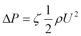
表3给出了不同进口水流速度下进出水口的压差值。当水冷LED灯装置的入口处水流速度分别为0.10、0.15、0.20和0.25 m/s时,管道对水流的阻力损失分别为13.2、25.7、41.9和62.5 Pa,根据伯努利方程,流体阻力损失与流速存在如下关系式:

式中Δ为进、出口水流压差,Pa;ζ为灯管流道的阻力系数,无量纲;为水流速度,m/s。对管道压差与进口流速进行非线性二次拟合得到水冷LED灯管阻力系数ζ为2.2。

表3 不同进口水流速度下进出水口的压差与温差
植物工厂中多以种植叶菜为主,光期环境温度设置为26 ℃[39]。为保证LED光源释放的热量能被水流带走,则灯管金属外壳温度应不高于环境温度。因此,在入口流速分别为0.10、0.15、0.20和0.25 m/s时,灯管能串联的最大数量分别为6、10、12和18根,串联灯管进出口水流压差分别达到79.2、257、502.8和1 116 Pa。
2.2.2 入口流速对灯管降温效果影响
图4显示了入口流速分别为0.10、0.15、0.20和0.25 m/s条件下,水冷LED灯装置内的温度云图。温度云图从上至下分为2组,分别表示灯管对称面=0,出口处灯管横截面=−570 mm 2个特征面的温度分布。从图4可以看出,沿着水流方向灯管温度逐渐升高。对比不同流速下的灯管温度分布发现,随着入口流速的增加,灯管装置整体区域的温度下降,降温效果变好。其原因在于增加水流速度加快了水流与灯管接触面间的对流换热,促进灯管热量的转移。表2给出了不同进口水流速度下进出水口的温差值。当入口水流温度为17 ℃,水流速度分别为0.10、0.15、0.20和0.25 m/s时,进出水温差分别为1.4、0.9、0.7和0.5 ℃。图4显示在近水流出口的横截面上,灯管金属散热罩,灯珠芯片和水流温度分布比较均匀,灯罩温度相对较高。
注:灯管对称面(=0);出水口处灯管截面(=−570 mm)。
Note: Symmetry plane of lamp (=0); Lamp cross section near water outet (=−570 mm).
图4 不同入口速度水冷LED灯管装置温度云图
Fig.4 Temperature magnitude contour of water-cooled LED with different inlet water velocity
入口流速0.10、0.15、0.20和0.25 m/s条件下灯管各部分的温度体积加权平均值如图5所示。当进口水流速从0.10 m/s增加到0.25 m/s时,灯管内空气、灯珠芯片、金属散热管和水流区域的平均温度分别下降了0.3、0.3、0.3和0.4 ℃。灯管的高温区域主要集中在灯管内空气区域,其主要原因是外环境温度设置为24 ℃,灯罩吸收的外部热量不能迅速被管道中的水流带走。不同入口水流速度下灯管金属散热罩,灯珠芯片和水流区域温度差异不显著,进一步说明了水冷LED灯管装置的散热效果较好,LED芯片产生的热量能迅速被水流带走。
3 结 论
本研究针对植物工厂人工光源散热量大、环控系统能耗高的问题,设计了一种以液体为热传导介质的通用型水冷LED灯管,并通过CFD数字模型的构建对不同水流情况下水冷LED灯管温度分布及水流压降的影响进行了模拟,为实际使用中需要明确的冷却水温度、水流速度、串接数量等关键参数提供了理论依据,有效指导了水冷灯管在植物工厂中的安装与使用。研究主要结论如下:
1)通过模拟和实测进水温度为24 ℃,流速为0.2 m/s条件下LED灯管金属散热管、灯罩和出口水流温度,得到模拟结果与试验结果百分比误差在16.4%以内,构建的水冷LED灯管CFD模型能准确描述水流温度与速度对水冷LED灯管的降温效果影响,为水冷LED灯管的研究及应用提供了理论基础。
2)利用验证的模型模拟不同入口速度对灯管热耗散的影响,结果表明:入口流速的增加,加速了灯珠芯片热量被水流带走,在入口水温为17 ℃,入口速度分别为0.10、0.15、0.20和0.25 m/s时,进出水温差分别为1.4、0.9、0.7和0.5 ℃。植物工厂中对水冷LED灯管进行串联时,应根据进水温度和环境温度的差来计算可串接灯管数量。
3)入口流速的增加亦会增加水流阻力,本试验设计的圆形锯齿水冷LED灯管对水流的阻力系数为2.2。在实际植物工厂生产中,应根据水流速度和串联灯管数量计算总水流压力损失,该计算结果可为水泵选型提供依据。
[1] 杨其长. 植物工厂[M]. 北京:清华大学出版社,2019.
[2] Ioslovich I, Gutman P O. Optimal control of crop spacing in a plant factory[J]. Automatica, 2000, 36(11): 1665-1668.
[3] Kato K, Yoshida R, Kikuzaki A, et al. Molecular breeding of tomato lines for mass production of miraculin in a plant factory[J]. Journal of Agricultural and Food Chemmistry. 2010, 58(17): 9505-9510.
[4] Miyagi A, Uchimiya H, Kawaiyamada M. Synergistic effects of light quality, carbon dioxide and nutrients on metabolite compositions of head lettuce under artificial growth conditions mimicking a plant factory[J]. Food Chemistry, 2017, 218: 561-568.
[5] Doo H S, Bae H J, Kim S J. Production of Korean ginseng plants (Panax ginseng C. A. Meyer) in fully closed plant factories[J]. Acta Horticulturae, 2014, 1037: 777-782.
[6] Johkan M, Shoji K, Goto F, et al. Effect of green light wavelength and intensity on photomorphogenesis and photosynthesis in Lactuca sativa[J]. Environmental and Experimental Botany, 2012, 75: 128-133.
[7] Okamura K, Matsuda Y, Igari K, et al. The optimal harvesting time of vaccine-producing transgenic lettuce cultivated in a closed plant factory[J]. Environmental Control in Biology, 2014, 52(1): 57-61.
[8] Park J, Nakamura K, Nishiura Y, et al. Cultivation of lettuce and considerations of suitable item in plant factory adopted automatic transportation system[J]. IFAC Proceedings Volumes, 2013, 46(4): 328-331.
[9] Wang J, Lu W, Tong Y, et al. Leaf morphology, photosynthetic performance, chlorophyll fluorescence, stomatal development of lettuce (L.) exposed to different ratios of red light to blue light[J]. Front Plant Sci, 2016, 7: 250.
[10] Lin M, Chang C, Horng R, et al. Heat dissipation performance for the application of light emitting diode[J] Symposium on Design, Test, Integration & Packaging of Mems/moems, IEEE, 2009.
[11] Kozai T. Sustainable plant factory closed plant production systems with artificial light for high resource use efficiencies and quality produce[J]. Acta Horticulturae, 2013, 1004: 27-40.
[12] Muthu S, Schuurmans F, Pashley M. Red, green and blue LEDs for white light illumination[J]. Selected Topics in Quantum Electronics, IEEE, 2002, 8(2): 333-338.
[13] Barton D, Osinski M, Perlin P, et al. Single-quantum well InGaN green light emitting diode degradation under high electrical stress[J]. Microelectronics Reliability, 1999, 39(8): 1219-1227.
[14] Nadarajah N, Yimin G. Life of LED-based white light sources[J]. Osa Journal of Display Technology, IEEE, 2005, 1(1): 167-171.
[15] Ruter J, Ingram D. 13Carbon-labeled photosynthate partitioning in Ilex crenata ‘Rotundifolia’ at supraoptimal root-zone temperatures[J]. Journal of the American Society for Horticultural Science, 1990, 115(6): 1008-1013.
[16] Walker J. One–degree increments in soil temperature affect maize seedling behavior[J]. Soil Science Society of America Journal, 1969, 33(5): 729-736.
[17] Nakamoto H, Hiyama T. Heat-shock proteins and temperature stress. Handbook of Plant and Crop Stress[M]. New York: Marcel Dekker, 1999.
[18] Raju P, Clark R, Ellis J, et al. Effects of species of VA-mycorrbizal fungi on growth and mineral uptake of sorghum at different temperatures[J]. Plant and Soil, 1990, 121(2): 165-170.
[19] Tindall J, Millss H, Radcliffe D. The effect of root zone temperature on nutrient uptake of tomato[J]. Journal of Plant Nutrition, 1990, 13(8): 939-956.
[20] Cumbus I, Nye P. Root zone temperature effects on growth and phosphate absorption in rape Brassica napus cv. Emerald[J]. Journal of Experimental Botany, 1984, 36(2): 219-227.
[21] Simonne A, Simonne E, Eitenmiller R, et al. Bitterness and composition of lettuce varieties grown in the southeastern United States[J]. Hort Technology, 2002, 12(4): 721-726.
[22] Jenni S, Yan W. Genotype by environment interactions of heat stress disorder resistance in crisphead lettuce[J]. Plant Breed, 2009, 128(4): 374-380.
[23] Zhao X, Carey E. Summer production of lettuce, and microclimate in high tunnel and open field plots in Kansas[J]. Hort Technology, 2009, 19(1): 113-119.
[24] Bunning M, Kendall P, Stone M, et al. Effects of seasonal variation on sensory properties and total phenolic content of 5 lettuce cultivars[J]. Journal of Food Science, 2010, 75(3): 156-161.
[25] Fukuda M, Matsuo S, Kikuchi K, et al. Isolation and functional characterization of the flowering locus T homolog, the LsFT gene, in lettuce[J]. Journal of Plant Physiology, 2011, 168(13): 1602-1607.
[26] Goto E, Takakura T. Prevention of lettuce tipburn by supplying air to inner leaves[J]. Transactions of the ASAE, 1992, 35(2): 641-645.
[27] Shibata T, Iwao K, Takano T. Effect of vertical air flowing on lettuce growing in a plant factory[J]. Acta Horticulturae, 1995, 399: 175-183.
[28] Shibuya T, Tsuruyama J, Kitaya Y, et al. Enhancement of photosynthesis and growth of tomato seedlings by forced ventilation within the canopy[J]. Scientia Horticulturae, 2006, 109: 218-222.
[29] Moon S, Kwon S, Lim J. Minimization of temperature ranges between the top and bottom of an air flow controlling device through hybrid control in a plant factory[J]. The Scientific World Journal, 2014: 1-7.
[30] 李琨,邹志荣. 植物工厂生菜根际通风对冠层及根际环境影响[J]. 农业工程学报,2019,35(7):178-187.
Li Kun, Zou Zhirong. Environmental effects of root zone ventilation on canopy and rhizosphere of lettuce in plant factory[J]. Transactions of the Chinese Society of Agricultural Engineering (Transactions of the CSAE), 2019, 35(7): 178-187. (in Chinese with English abstract)
[31] 侯亭波. 凹穴型复杂微通道换热器结构设计及流动与传热性能研究[D]. 合肥:合肥工业大学,2019.
Hou Tingbo. Structural Design and Study on Performance of Flow and Heat Transfer of Complex Microchannel Heat Exchanger with Reentrant Cavitives[D]. Hefei: Hefei University of Technology, 2019. (in Chinese with English abstract)
[32] 王杰,李健,范冰丰,等. 大功率紫外LED水冷设计及模拟优化[J]. 机械设计与制造,2018(1):212-214.
Wang Jie, Li Jian, Fan Bingfeng, et al. Design and optimization of an UV-LED water-cooled panel model[J]. Machinery Design and Manufacture, 2018(1): 212-214. (in Chinese with English abstract)
[33] 刘晓英,焦学磊,要旭阳,等. 水冷式植物工厂LED面光源及散热系统的研制与测试[J]. 农业工程学报,2015,31(17):244-247.
Liu Xiaoying, Jiao Xuelei, Yao Xuyang, et al. Design and test of LED surface light source used in plant factory with water-cooling system[J]. Transactions of the Chinese Society
of Agricultural Engineering (Transactions of the CSAE), 2015, 31(17): 244-247. (in Chinese with English abstract)
[34] Patankar S V. Numerical heat transfer and fluid flow[M]. Washington, WA: Hemisphere Publishing Corporation, 1980.
[35] British Standards Institution. Heating systems in buildings-Design for water-based heating systems: BS EN12828-2012[S]. Britain: BSI standards Limited, 2003.
[36] 许馨尹,于军琪,李红莲,等. 露点温度计算方法对比研究[J]. 气象与环境学报,2016,32(3):107-111.
Xu Xinyin, Yu Junqi, Li Honglian, et al. Comparative study on calculation methods of dew point temperature[J]. Journal of Meteorology and Environment. 2016, 32(3): 107-111. (in Chinese with English abstract)
[37] Nelson J A, Bugbee B. Supplemental greenhouse lighting: Return on investment for LED and HPS fixtures[J]. Controlled Environments, 2013, 7: 1-9.
[38] Tamimi E, Kacira M, Choi C Y, et al. Analysis of microclimate uniformity in a naturally vented greenhouse with a high-pressure fogging system[J]. Transactions of the ASABE, 2013, 56(3): 1241-1254.
[39] Zha L Y, Liu W K, Yang Q C, et al. Regulation of ascorbate accumulation and metabolism in lettuce by the Red: Blue ratio of continuous light using LEDs[J]. Frontiers in Plant Science, 2020, 5(11): 1-13.
Numerical simulation of the cooling efficiency of circular serrated water-cooled LEDs using CFD in plant factory
Fang Hui, Cheng Ruifeng, Tong Yuxin, Li Kun※
(1.,,100081,; 2.,,100081,)
LEDs are more commonly used than fluorescent lamps in plant factories with artificial light for energy savings. But the LEDs cannot convert the input power to light at 100 % efficiency. Part of energy can be converted into heat, and then be transferred to the ambient environment, in terms of heat conduction, radiation, and convection. However, heat dissipation of LEDs has become a great challenge, as the power increased while the volume of LEDs reduced. In this study, a circular serrated water-cooled LED was designed to transmit the heat generated by LEDs in time for a longer service life. A three-dimensional Computational Fluid Dynamic (CFD) model was developed to assess the design, where the LED bubbles were set as the internal heat source. The electrical efficiency was assumed to be 32% and 49% in the red and blue LEDs, respectively. The heat flux of 1.7×10⁷W/m3was calculated, according to the number of lamp beads and the electrical to light conversion efficiency. The constructed grids were approximately 1 162 800 for each case, including 220 881 nodes with a minimum element size of 2 mm. Much finer meshes were automatically imposed near the bubbles with proximity and curvature size functions in meshing. The SIMPLE was selected for the pressure-velocity coupling. A least-square cell-based scheme was used for the gradient term in spatial discretization. The second-order scheme was applied for the pressure term. The second-order upwind discretization schemes were used for momentum and energy equations, whereas, the first-order upwind discretization schemes were used for turbulence equations, mainly for higher accuracy. The convergence criterion was set as 10-6on energy and 10-3on continuity, momentum and viscous terms. Inlet and outlet boundary conditions were set for the numerical solution using the velocity-inlet and pressure-outlet. The inlet water velocity and water temperature were set as 0.2 m/s and 24 ℃, respectively. The simulated value of the LED water-cooled lamp was close to the measured value, with the maximum error of 16.4%, indicating that the CFD model could accurately simulate the temperature distribution of each structure of the lamp. The validated model was used to simulate the influence of different water flow velocities on the temperature distribution and water flow pressure drop in a water-cooled LED lamp. The results showed that the temperature distribution of bubbles and water flow was relatively uniform, and the structure of the lamp was reasonable. The heat released by the bead chip was quickly transferred into the water flow; when the inlet velocity of the lamp increased from 0.10 to 0.25 m/s, and the difference of water temperature between the inlet and outlet dropped from 1.4 ℃ to 0.5 ℃. Therefore, a series of connected lamps were calculated, according to the temperature difference between the inlet water and the ambient air, when the water-cooled LED lamps were connected in series. The inlet flow velocity also improved the flow resistance, where the resistance coefficient of lamps to the water flow was 2.2.
temperature;computational fluid dynamics; plant factory; supplementary light; simulation; water flow velocity
2020-10-10
2021-01-12
中央级公益性科研院所基本科研业务费专项(Y2020GH02)
方慧,硕士,副研究员,研究方向为设施环境模拟。Email:fanghui@caas.cn
李琨,博士,副研究员,研究方向为设施园艺。Email:likun@caas.cn
10.11975/j.issn.1002-6819.2021.07.026
S625.4
A
1002-6819(2021)-07-0212-06
方慧,程瑞锋,仝宇欣,等. 基于CFD的植物工厂圆形锯齿状水冷LED灯管降温效果数值模拟[J]. 农业工程学报,2021,37(7):212-217. doi:10.11975/j.issn.1002-6819.2021.07.026 http://www.tcsae.org
Fang Hui, Cheng Ruifeng, Tong Yuxin, et al. Numerical simulationof the cooling efficiency of circular serrated water-cooled LEDs using CFD in plant factory[J]. Transactions of the Chinese Society of Agricultural Engineering (Transactions of the CSAE), 2021, 37(7): 212-217. (in Chinese with English abstract) doi:10.11975/j.issn.1002-6819.2021.07.026 http://www.tcsae.org
