Designing Electrolyzers for Electrocatalytic CO2 Reduction
2021-06-02DunfengGaoPengfeiWeiHefeiLiLongLinGuoxiongWangXinheBao
Dunfeng Gao , Pengfei Wei , Hefei Li , Long Lin , Guoxiong Wang , Xinhe Bao
1 State Key Laboratory of Catalysis, Dalian National Laboratory for Clean Energy, Dalian Institute of Chemical Physics, Chinese Academy of Sciences, Dalian 116023, Liaoning Province, China.
2 University of Chinese Academy of Sciences, Beijing 100049, China.
Abstract: The electrocatalytic CO2 reduction reaction (CO2RR)driven by renewable energy is an efficient approach to achieve the conversion and utilization of CO2. In this context, CO2RR has become an emerging research focus in the field of electrocatalysis over the past decade. While a large number of nanostructured catalysts have been developed to accelerate CO2RR, the tradeoff between activity and selectivity usually renders the overall electrocatalytic performance very poor. Beyond catalyst design, rationally designing electrolyzers is also of substantial importance for improving the CO2RR performance and achieving its scale-up for practical applications. To a large extent,the electrolyzer configuration determines the local reaction environment near an electrode by affecting the process conditions,thereby resulting in remarkably different electrocatalytic performances. To be techno-economically viable, the performance of CO2 electrolyzers is expected to be at least comparable to that of the current state-of-the-art proton exchange membrane(PEM) water electrolyzers, with regard to their activity, selectivity, and stability. Researchers have made great progress in the development of CO2 electrolyzers over the past few years, but they are also facing many issues and challenges. This review aims to provide an in-depth analysis of the research progress and status of current CO2 electrolyzers including H-cell, flow-cell, and membrane electrode assembly cell (MEA-cell) electrolyzers. Herein, operation at industrial current densities (> 200 mA·cm-2) is set as a basis when these electrolyzers are discussed and compared in terms of the four main figures of merit (current density, Faradic efficiency, energy efficiency and stability) that describe the CO2RR performance of an electrolyzer. The advantages and drawbacks of each electrolyzer are discussed and highlighted with emphasis on the key achievements reported to date. Compared to conventional H-cell electrolyzers that work well in mechanistic studies, the newly developed electrolyzers using gas diffusion electrodes, both flow-cell and MEA-cell electrolyzers, are able to break the limitation of CO2 solubility in water and acquire industrial current densities. Although flow-cell electrolyzers have achieved current densities exceeding 1 A·cm-2, they suffer from low energy efficiencies because of the significant iR drop and poor stability owing to the use of alkaline electrolytes. These issues can be overcome in the case of zero-gap MEA-cell electrolyzers with ion exchange membranes being as solid electrolytes. The anion exchange membrane (AEM)-based CO2 electrolyzers are at the center of the current research, as they demonstrate promising activity and selectivity toward specific CO2RR products and exhibit excellent stability for over thousands of hours in few cases. Meanwhile, the crossover of CO2 and liquid products from the cathode to the anode through the membrane tends to lower the utilization efficiency of the CO2 supplied to the AEM electrolyzers. MEA-cell electrolyzers using cation exchange membranes and bipolar membranes have also been explored; however, neither of them have shown satisfactory CO2RR performance. The development of new polymer electrolyte membranes and ionomers would help address these problems. While issues and challenges still exist, MEA-cell electrolyzers hold the greatest promise for practical applications.As concluding remarks, research strategies and opportunities for the future have been proposed to accelerate the development of CO2RR technology for practical applications and to deepen the mechanistic understanding behind improved performance. This review provides new insights into rational electrolyzer design and guidelines for researchers in this field.
Key Words: CO2 electrolyzers; Electrocatalytic reduction; Energy efficiency; Industrial current density; Flow cell;Membrane electrode assembly
1 Introduction
The energy crisis and climate change facing humanity are great threats to the sustainable development of economy, society and environment. Carbon dioxide (CO2) derived from the combustion of fossil fuels including coal, petroleum and natural gas has been considered as the principal contributor to global warming. Coupled with the rapidly growing renewable energy,electrocatalytic CO2reduction reaction (CO2RR) converts the waste CO2into chemicals and fuels as well as stores intermittent renewable electricity in the form of chemical energy1-7. As the CO2molecule is both thermodynamically and kinetically stable,CO2RR is a quite challenging electrocatalytic reaction. A few techno-economic analysis studies have shown that the CO2RR process aiming at practical applications should be efficient enough in terms of activity, selectivity and stability at industrial levels8-11. To drive this difficult process more efficiently, most of current studies focus on developing nanostructured CO2RR catalysts and have made significant progress in improving selectivity of specific products12-21.
Beyond catalysts, another important aspect that determines activity, selectivity and stability of CO2RR is reaction environment, especially the local environment near electrode surface. Numerous factors affecting the reaction environment of CO2RR have been investigated, such as temperature, pressure,pH, solvent, membrane, potential, current density, electrolyte composition and electrolyzer configuration20-31. Of them, the choice of the CO2electrolyzer configuration would usually decide how other factors are implemented into the CO2RR process22,23. Recently rational design and optimization of electrolyzers32-42has been proven as an efficient approach for improving CO2RR performance. In this review we firstly introduce four main figures of merit (current density, Faradaic efficiency, energy efficiency and stability) that describe CO2electrolyzers for CO2RR at industrial current densities. Next we give an overview of current electrolyzer configurations and summarize recent research progress of each electrolyzer with emphasis on their advantages and drawbacks. At the end we discuss existing challenges in the field of CO2electrolyzers and propose new research strategies and opportunities in the future development of this area.
Achieving highly efficient CO2RR requires not only highly active, selective and stable catalysts for both cathode reaction(CO2RR) and anode reaction (O2evolution reaction, OER), but also electrolyzers with low Ohmic resistance and sufficient mass transport under reaction conditions9,43. Towards practical applications of CO2RR, the overall performance of the whole CO2RR process must be evaluated at both catalyst and device levels44,45. The performance of an electrocatalytic process is commonly characterized by four main figures of merit including current density, Faradaic efficiency, energy efficiency and stability. In the cases of energy efficiency and stability, the corresponding values of the whole electrolyzer rather than only that of cathode CO2RR catalysts should be reported for assessing the CO2RR process. The current density, energy efficiency and stability of an efficient industrial CO2RR process are expected to be at least comparable to those of current state-of-the-art proton exchange membrane (PEM) water electrolysis46,47.
2 Figures of merit
Current density is a measure of activity or reaction rate of an electrocatalytic reaction. Although electrochemically active surface area (ECSA) normalized current density is preferred to compare intrinsic catalytic activity in fundamental electrocatalysis studies48, geometric current density based on electrode size is usually used for reporting electrocatalytic properties owing to its direct correlation to the overall device performance. Electrolyzer evaluation facing practical applications should be conducted at industrial current densities(> 200 mA·cm-2) and very recently current densities up to A·cm-2have been already reported49,50.
Faradaic efficiency is defined as the percentage of the charge that is consumed for the production of a given product in the total charge that flows through an electrolyzer. It is a measure of product selectivity based on electron number, slightly different from the selectivity on the basis of carbon number reported in thermal catalysis studies. In addition, it also incorporates the H2produced from competitive hydrogen evolution reaction (HER)into product distribution. Nevertheless, near-unity Faradaic efficiency of a target product is ideal, as it substantially reduces the cost of downstream separation and purification.
The Faradaic efficiency of a specific product is calculated as follows:

where εFaradaic,iis the Faradaic efficiency of product i, %; Qtotalis the consumed total charge, C; Qiis the charge used for the production of product i, C; Niis the amount of product i, mol; niis the number of electrons transferred to form product i; F is Faraday constant, which is 96485 C·mol-1.
Energy efficiency is defined as the percentage of the energy that is stored as chemical energy in a specific product in the applied electrical energy. It is a measure of conversion efficiency of electric energy to chemical energy. For an endothermic reaction like CO2RR, the enthalpy change between reactants and products is provided by both electricity and heat (ΔH = ΔG +TΔS). When no external heating system is available, the heat needed for the reaction is actually supplied by the Joule heat produced within the electrolyzer. The thermoneutral voltage(En), at which the heat (TΔS) needed for the reaction is equal to the Joule heat, is defined as the minimum thermodynamic cell voltage to provide the required enthalpy change only through electrical energy51,52. Thermoneutral voltage corresponds to the enthalpy change for a given reaction, while equilibrium voltage(E0) corresponds to the change in the Gibbs free energy.Therefore, energy efficiency should be calculated based on thermoneutral voltage51,52and it also includes Faradaic efficiency and overpotential that is defined as the difference between thermoneutral voltage and applied cell voltage.
The energy efficiency for the production of a specific product is defined as follows:
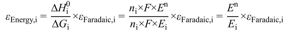
where εEnergy,iis the energy efficiency for the formation of product i, %; ΔHi0is the theoretical enthalpy change of product i, kJ·mol-1; ΔGi0is the change in the Gibbs free energy of product i, kJ·mol-1; εFaradaic,iis the Faradaic efficiency of product i, %; niis the number of transferred electrons to form product i;F is Faraday constant, which is 96485 C·mol-1; Enis the thermoneutral voltage, V; Eiis the applied cell voltage, V.
Stability describes the changes of current density, Faradaic efficiency and energy efficiency as a function of time. Apparent changes of above parameters may be caused by the deactivation of catalysts as well as the degradation of other aspects such as membrane, impurities, operating conditions and electrode flooding. To date stability is the least studied figure of merit in the field of CO2RR. Unlike the relatively mature thermal catalysis, there are still no well-recognized protocols for conducting stability measurements in a proper manner53. Most of current studies conduct stability tests at a lab scale, tens to a couple of hundreds of hours, and catalyst stability is mostly focused54. From a point of view of practical applications,however, the stability of the whole electrolyzer should be investigated at a time scale of thousands of hours, even years.More importantly, the good stability should not be at the expense of activity and selectivity. Stability studies at industrial current densities are recommended.
Ideally an efficient electrolyzer should achieve all of the four figures of merit with high values; however increasing cell voltage to improve current density would necessarily decrease energy efficiency. For better cost-effectiveness in practical applications, high reaction rate (current density) should be guaranteed at the expense of energy efficiency to some extent8-11.In the following sections, we will discuss current CO2electrolyzers with emphasis on the four figures of merit of different configurations.
3 Electrolyzer configuration
CO2RR performances are usually measured in H-cell electrolyzers with a piece of ion exchange membrane separating anode and cathode compartments, as shown in Fig. 1a. The role of the membrane is to prevent the re-oxidation of CO2RR products over anode and to use different electrolytes in anode and cathode compartments in particular cases. Metal foil catalysts or powder catalysts deposited on conductive but inactive substrates serve as cathodes (working electrodes). The potential applied to cathode is controlled precisely using a reference electrode placed close to working electrode. This is important to the fundamental studies of potential-dependent product distribution and structural changes of catalysts under reaction conditions55. Although only cathode potentials are reported in the literature, the huge Ohmic resistance due to the large distance between anode and cathode (a few of centimeters),ion exchange membrane and dilute electrolytes (usually 0.1 mol·L-1), would cause very high cell voltages and thus quite low energy efficiency. Another drawback of the H-cell electrolyzer is its low upper current density (only a few tens of mA·cm-2) due to the finite CO2solubility (33 mmol·L-1at 25 °C and 101325 Pa56) in aqueous electrolytes. Such limitations hinder its scaleup and practical applications.
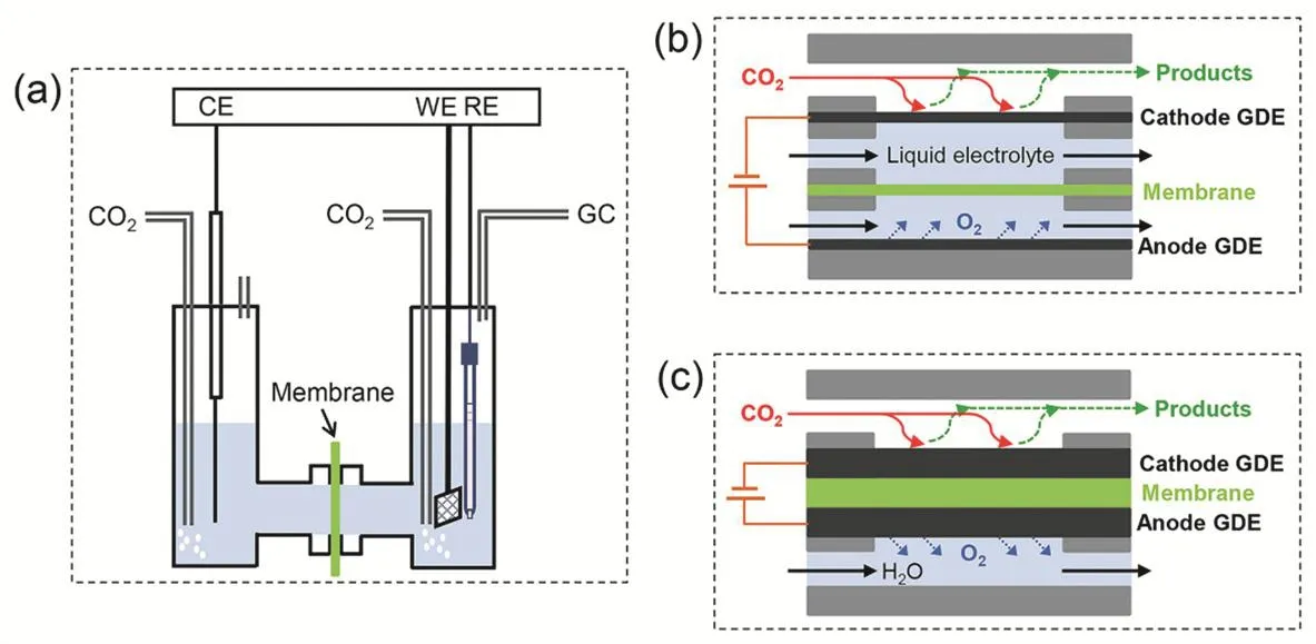
Fig. 1 Schematic diagrams of CO2 electrolyzers.

Fig. 2 (a) Schematic diagram of a gas diffusion electrode (GDE). Reproduced with the permission 57.Copyright 2018, Royal Society of Chemistry. (b) Photo of a membrane electrode assembly (MEA).
To address this issue, flow-cell electrolyzers (Fig. 1b) and membrane electrode assembly cell (MEA-cell) electrolyzers(Fig. 1c) have been developed recently. Both gas and liquid feeds are supplied to the electrolyzers continuously. The continuous operation mode makes the two electrolyzers more advantageous than the H-cell electrolyzer, a batch reactor. The key part to both electrolyzers is the gas diffusion electrode (GDE, Fig. 2a) where gas-liquid-solid interfaces are formed, allowing CO2to react in the form of gas rather than firstly being dissolved in aqueous solutions57. Although the GDE configuration fails to incorporate metal foil catalysts, its excellent suitability of measuring more practical powder catalysts is recommended for scale-up. The use of GDE provides possibility to operate electrolyzers at industrial current densities58. The main difference in the two electrolyzer configurations is the addition of a liquid electrolyte layer between cathode and ion exchange membrane in flow-cell electrolyzers. Similar to H-cell electrolyzers, flow-cell electrolyzers also benefit from the feasibility of inserting a reference electrode in the catholyte layer and suffer from high Ohmic drop and low energy efficiency. If the cathode is directly placed again the membrane without the presence of the catholyte layer, the cathode, membrane and anode constitutes MEA (Fig.2b). Different from H-cell and flow-cell electrolyzers with membrane being a separator, the membrane in MEA-cell electrolyzers works as a solid electrolyte. This zero-gap configuration reduces the distance between cathode and anode from several millimeters to the thickness of the membrane (only a few tens of micrometers), which would significantly decrease the Ohmic resistance and improves energy efficiency38,39. If dry CO2and water are fed into cathode and anode compartments of MEA-cell electrolyzers, respectively (Fig. 1c), CO2electrolysis with pure water38is achieved like the relatively more mature alkaline polymer electrolyte water electrolysis technique59. Due to the compact geometry of the MEA configuration, it is not realistic to precisely measure potentials applied to cathodesviafor instance using a reference electrode. This disadvantage brings troubles into the fundamental catalysis research in MEA-cell electrolyzers.
The main features of the three CO2electrolyzers are summarized in Table 1. While H-cell electrolyzers have played a vital role in fundamental CO2RR studies, MEA-cell electrolyzers are the most likely candidate for achieving costeffective industrial CO2RR. Given that the fact that the development of high-performance membranes urgently needed for MEA-cell electrolyzers is relatively lagging60,61, flow-cell electrolyzers seem to serve as a transition before reaching the ultimate goal. Solid oxide electrolysis cell (SOEC) working at high temperature (> 600 °C) is another important CO2electrolyzer62, but it is out of the scope of this review. Interested readers may refer to previous excellent reviews on this topic63,64.
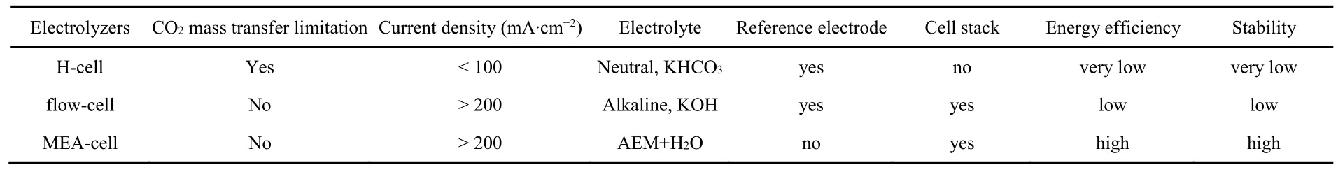
Table 1 Main features of three CO2 electrolyzers.
4 Research progress in H-cell electrolyzers
H-cell electrolyzers have been widely used to evaluate CO2RR performance since 1980s when the group of Prof. Hori started pioneering studies in the field65,66. Due to their simple configuration and easy operation, H-cell electrolyzers are usually the first choice in mechanistic studies. While current densities are limited in H-cell electrolyzers, high selectivities towards target products that are often determined by intrinsic properties of catalysts have been reported in previous studies55,67-69. For example, both formate and CO, two important C1products, can be produced with high Faradaic efficiency of > 90% over Pd nanoparticlesviaengineering active phases and reaction pathways (Fig. 3a)55. Compared to polycrystalline Cu with poor C―C coupling ability, halide-modified Cu catalysts with metastable Cu+species under reaction conditions achieves a Faradaic efficiency of 80% for total multicarbon (C2+) products includingethylene, ethanol and 1-propanol (Fig. 3b)67. A very recent work further improves the selectivity of single C2+product and reports an ethylene Faradaic efficiency as high as 83% over Cu nanosheets with nanoscaled defects (Fig. 3c)68.
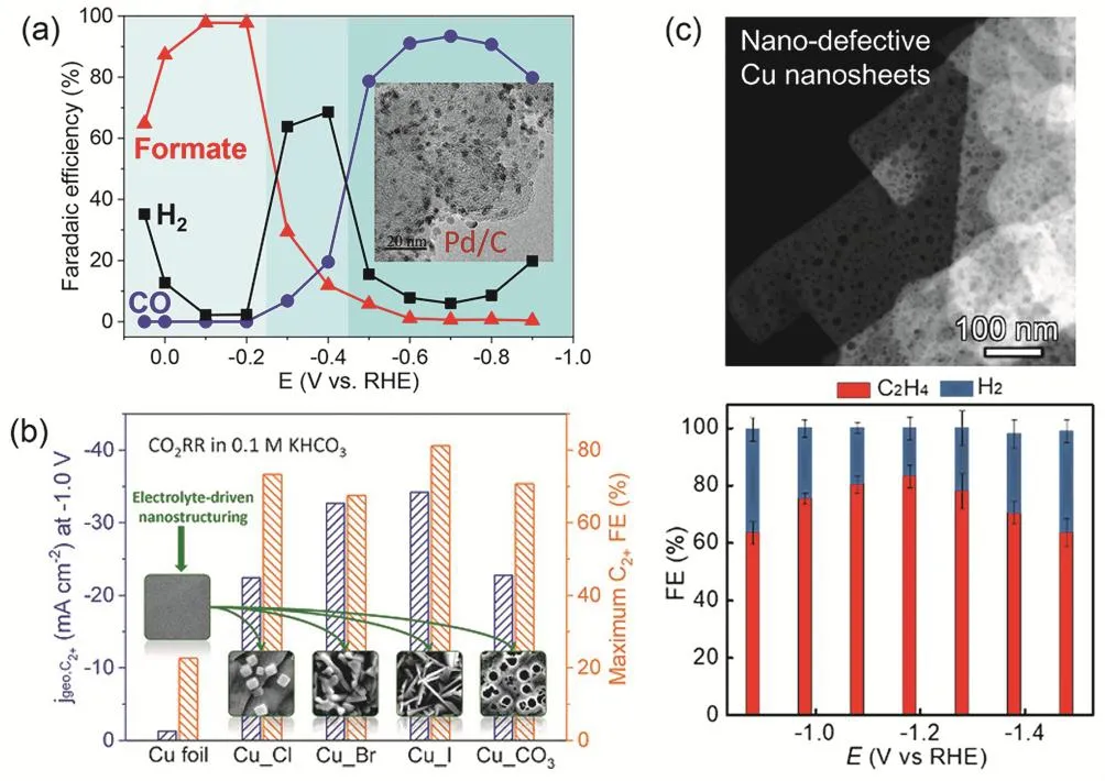
Fig. 3 (a) Faradaic efficiencies of formate, CO and H2 as a function of applied potential over Pd/C catalyst. Reproduced with the permission 55.Copyright 2017, Springer Nature. (b) Partial current density at -1.0 V vs RHE and maximum Faradaic efficiency of C2+ products over halide- and carbonate-modified Cu catalysts. Reproduced with the permission 67. Copyright 2019, Wiley. (c) Faradaic efficiencies of C2H4 and H2 as a function of applied potentials over nanoporous Cu nanosheets. Reproduced with the permission 68. Copyright 2020, American Chemical Society.All the performances (a-c) were measured in H-cell electrolyzers.
In spite of such progress in catalyst design, researchers have also tried to improve CO2RR selectivity by optimizing local reaction environments near electrode surfaces in H-cell electrolyzers. The strategies are to tune operating parameters such as electrolyte composition, mass transfer as well as the more general temperature and pressure20,21,70. While higher temperature is more favorable for the competitive HER over CO2RR, the elevated pressure increases CO2solubility and thus the supply of CO2to catalysts (Fig. 4a) via the equilibrium between CO2and bicarbonate71,72, probably leading to the suppression of HER. With this idea, a high-pressure H-cell electrolyzer with CO2partial pressure up to 60 atm (1 atm =101325 Pa) was designed. Consequently the H2formation is almost completely suppressed and more interestingly the selectivity of CO2RR shifts from complex C1-C3products at 1 atm to formate, a single C1product, with Faradaic efficiency of >98% at ≥ 45 atm (Fig. 4b)32. The electrocatalytic reduction of supercritical CO2, completely free of mass transfer, has been also explored, aiming to combine the benefits of high selectivity at elevated pressure and high reaction rate at elevated temperature in one system73.
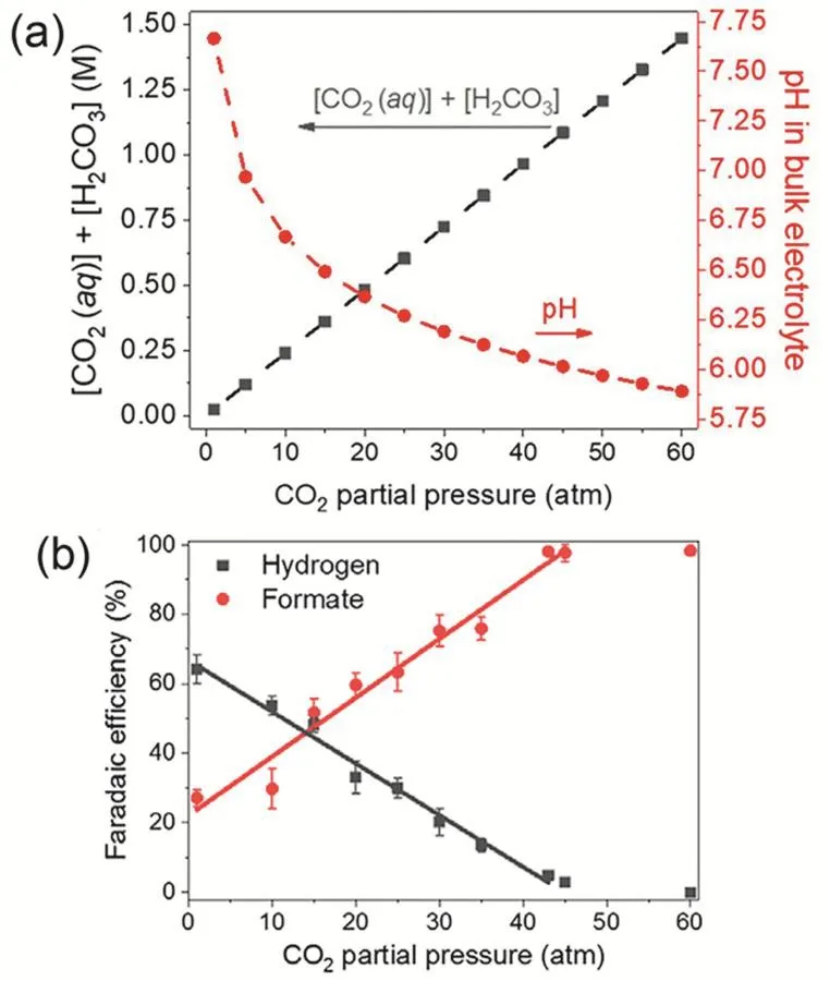
Fig. 4 (a) Calculated concentrations of active carbon species and bulk pH in 0.5 mmol·L-1 KHCO3 as a function of CO2 partial pressure at 25 °C. (b) Formate and hydrogen FEs as a function of CO2 partial pressure at -0.64 V vs RHE over Cu2O/Cu cathode. Reproduced with the permission 32. Copyright 2020, American Chemical Society.
5 Research progress in flow-cell electrolyzers
As CO2reacts with OH-to form carbonate or bicarbonate anions, alkaline electrolytes are not feasible in aqueous CO2RR that proceeds in H-cell electrolyzers. On the other hand, high(local) pH is favorable for suppressing HER and enhancing C―C coupling25,35,74. The implementation of GDE in flow-cell electrolyzers (Fig. 1b) separates flow fields of CO2and liquid electrolyte, allowing the use of highly concentrated KOH with up to 10 mol·L-135. The selectivity shift in alkaline environments in combination with high current densities benefited from the GDE configuration makes flow-cell electrolyzers suitable for studies closer to practical applications49,50,75,76. The Kenis group at the University of Illinois at Urbana Champaign has contributed a lot to the development of flow-cell electrolyzers34,76-79, and with rational system design including electrolyte engineering and process optimization they achieve a CO partial current density of 866 mA·cm-2with Faradaic efficiency of 98% in CsOH-based catholyte76. In 2018, the Sargent group made a breakthrough and reported highly selective CO2RR to ethylene using graphite/carbon/Cu/PTFE electrode35. The ethylene Faradaic efficiency reaches over 60% at the current density of 200-300 mA·cm-2, with a peak C2Faradaic efficiency of 83% at 275 mA·cm-2and -0.54 V vs RHE (Fig. 5a). A newly developed electrode configuration with sputtered Cu sandwiched between polytetrafluoroethylene (PTFE) membrane and carbon nanoparticles creates an abrupt reaction interface and thus maintains the ethylene Faradaic efficiency stable over a course of 150 h (Fig. 5b), although the current density gradually decreases from 100 to 75 mA·cm-2. Recently the Wang group at the Xiamen University achieves a record current density of 1.6 A·cm-2over a fluorine-modified Cu catalyst with C2+Faradaic efficiency of 80% (Fig. 5c), corresponding to~4.0 mmol·h-1·cm-2(Fig. 5d). They propose that C―C bonds in C2+products are formed via the hydrogen-assisted coupling of adsorbed CHO intermediates with the adsorbed hydrogen produced by fluorine enhanced water activation49.
At gas/liquid/solid three-phase boundaries in the GDE,carbonate/bicarbonate salts with lower solubility formed via reaction of CO2with alkaline electrolyte gradually makes the GDE more hydrophilic and being flooded over time80. The instability has been partially solved by increasing the hydrophobicity of gas diffusion layer using PTFE or fluoroalkyl silane35,49. Several groups also use bicarbonate solutions instead of alkaline solutions as catholyte to avoid salt deposition on GDE, but due to the lower ionic conductivity of bicarbonate salts the applied potentials are higher, leading to lower energy efficiency81-85. Nevertheless stability tests at industrial current densities presented in current literature are usually at a time scale of tens of hours49,86, with stable product distributions over time(Fig. 6a). The Schmid group at the Siemens company shows a stable CO2RR to CO at 300 mA·cm-2with CO Faradaic efficiency of near 70% for over 1200 hours (Fig. 6b). However,the cell voltage is quite high, from 7.0-7.5 V during the test87.
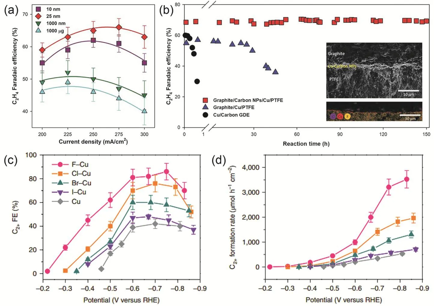
Fig. 5 (a) Ethylene faradaic efficiency as a function of current density in 10 mmol·L-1 KOH. (b) Stability test of the graphite/carbon/Cu/PTFE electrode in 7 mmol·L-1 KOH at -0.55 V vs RHE. (c) Faradaic efficiency and (d) formation rate of C2+ products over halide-modified Cu catalysts as a function of applied potentials in 1 mmol·L-1 KOH. Panels a, b reproduced with the permission 35. Copyright 2018, Science.Panels c, d reproduced with the permission 49. Copyright 2020, Springer Nature.
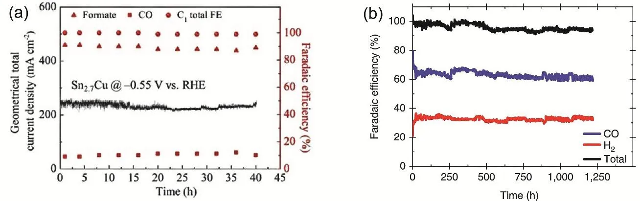
Fig. 6 (a) Stability test of Sn2.7Cu at -0.55 V vs RHE, with current density stable at around 240 mA·cm-2. Reproduced with the permission 86.Copyright 2020, Wiley. (b) Long-term stability of commercial Ag GDE at 300 mA·cm-2. The cell voltage stayed constant within 7.0-7.5 V during the test. Reproduced with the permission 87. Copyright 2018, Springer Nature.
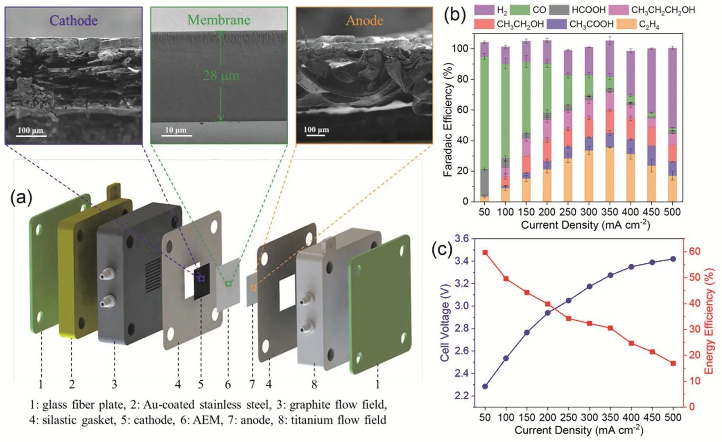
Fig. 7 (a) Schematic of AEM-based CO2 electrolyzer and cross-sectional SEM images of Pd/C cathode, QAPPT anion exchange membrane and IrO2-coated Ni foam anode; Faradaic efficiencies (b), cell voltage (c, left) and energy efficiency of total CO2RR products (c, right) of Cu cathode. Reproduced with the permission 39. Copyright 2020, Springer Nature.
Due to the presence of liquid catholyte layer between cathode and membrane, the energy efficiency of flow-cell electrolyzers is low, usually less than 20%87. From the point of view of practical applications, cathodic energy efficiency presented in the literature overestimates the actual energy efficiency of an electrolyzer device, since the former value benefits from iR compensation and the assumption that the overpotential of oxygen evolution reaction is zero49,79.
6 Research progress in MEA-cell electrolyzers
MEA-cell electrolyzers are considered as a direct translation of fuel cells and ion exchange membrane based water electrolyzers. Following well established approaches for PEM fuel cells and water electrolyzers, PEMs such as the Nafion membrane and phosphoric acid doped polybenzimidazole (PBI)membrane were firstly used in MEA-cell electrolyzers40,88-94.Owing to the acidic environment of PEMs favoring the competitive HER, PEM based CO2electrolyzers fail to achieve high Faradaic efficiency and industrial current density at the same time40,88-94.
In clear contrast, anion exchange membranes (AEMs)allowing the flow of OH-and water between cathode and anode have been widely implemented in CO2electrolyzers37-39,95-105.Our group has reported an AEM based electrolyzer (Fig. 7a) that can efficiently reduce CO2to CO over Pd/C catalysts and to C2+products over Cu catalysts39. Under optimized reaction conditions with PTFE as a binder in cathode catalyst layer and 0.1 mol·L-1KOH as anolyte, the total Faradaic efficiency of CO2RR over commercial Cu nanoparticles is over 80% at 350 mA·cm-2, with an energy efficiency of ~30% (Fig. 7b,c). Very recently we have further improved the CO2performance in such an electrolyzer by careful system optimization. A major issue that would cause gradual degradation of electrolyzer performance at industrial current densities is cathode flooding due to the accumulation of excess water. The flooding phenomenon could be mitigated by increasing hydrophobicity of the cathode using PTFE as a binder in cathode catalyst layer39,100.Compared to commonly used Nafion membrane in PEM fuel cells and water electrolyzers, the ion conductivity of current AEMs is usually not high enough and can be further enhanced by supplying liquid electrolytes to the anode. The supplied anolytes include KHCO3with 0.01 and 0.1 mol·L-137,39,95as well as KOH with 0.1 or 1 mol·L-196,100. Higher pH of the anolyte reduces cell resistance and facilitates the kinetics of oxygen evolution reaction at the anode, resulting in lower cell voltage and thus higher energy efficiency37,106. However, the corrosive alkaline electrolytes could have a detrimental effect on the mechanical stability of the electrolyzer.
The Zhuang group at the Wuhan University achieves CO2RR to CO in an AEM electrolyzer operated with dry CO2and pure water, free of both catholyte and anolyte38. Both AEM and anion exchange ionomer are made of a highly conductive and stable polymer, quaternary ammonia poly(N-methyl-piperidine-co-pterphenyl) (QAPPT). To make full use of the Joule heat produced due to cell resistance, the operating temperature was set at 60 °C.At a cell voltage of 3 V, the Au/C cathode achieves a current density of 500 mA·cm-2and a CO Faradaic efficiency of ~85%,resulting in an energy efficiency of ~42% (Fig. 8). This is the first CO2electrolyzer operating at industrial current densities,fully based on alkaline polymer electrolyte at the absence of any liquid electrolyte.
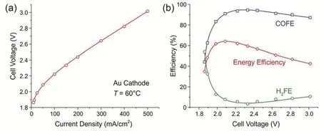
Fig. 8 (a) I-V curves and (b) CO Faradaic efficiency and energy efficiency as a function of cell voltage of Au/C catalysts at 60 °C. Pure water and dry CO2 are fed to anode and cathode, respectively. Reproduced with the permission 38. Copyright 2019, Royal Society of Chemistry.
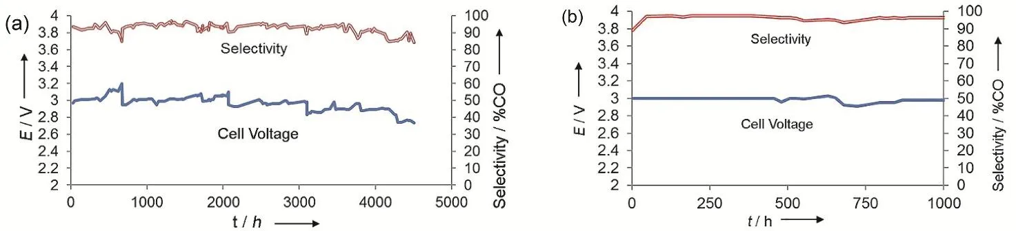
Fig. 9 Long-term stability tests of Ag nanoparticles (a) at 50 mA·cm-2 for 4380 h and (b) at 200 mA·cm-2 for 1000 h.Reproduced with the permission 37. Copyright 2017, Wiley.
While most studies conduct stability tests for no more than 200 h38,39,95-97,101, the Dioxide Materials company has managed to run stability for over 4000 h at a fixed current density of 50 mA·cm-2and for 1000 h at 200 mA·cm-2with a CO Faradaic efficiency of almost 100% (Fig. 9). Such outstanding stability relies on the excellent performance of the Sustainion membrane with an imidazolium group added onto the styrene side-chains37.When certain amounts of porous carbon and Sustainion ionomer are added to the cathode catalyst layer, the stability can be further improved, up to 3800 h (158 days), at a current density of 200 mA·cm-2and a cell voltage of ~3 V which translates to a CO2single pass conversion of ~25% and an energy efficiency of~50%99. These performances in terms of current density,Faradaic efficiency, energy efficiency and stability have paved the way for commercializing the CO2electrolysis process.
Assembling large-size and multilayer electrolyzer stacks is a good practice to scale up CO2RR. The Janaky group reported the first demonstration of a multilayer MEA-cell electrolyzer stack for CO2RR to CO107. The electrolyzers are connected, either in parallel where pure CO2is equally supplied to each electrolyzer(Fig. 10a) or in series where CO2and products flow through all the electrolyzers one by one (Fig. 10b). For the parallel connection, the performance of electrolyzer stack is identical to the sum of multiple single electrolyzers (Fig. 10c), but this connection decreases the capital investment costs from a technological perspective. On the other hand, the series connection significantly increases the single pass conversion of CO2compared to a single electrolyzer (Fig. 10d). Moreover, the CO2RR performance can be further improved by feeding pressurized CO2(up to 10 bar, 1 bar = 105Pa)107.
Unlike AEM water electrolzyers, the OH--exchange form of AEMs in the case of CO2electrolyzers cannot be sustained upon contact with the CO2feed due to a well-documented carbonation of the membrane that causes a rapid decrease (up to 10-fold) in the ionic conductivity108. The crossover of CO2via the cathodeto-anode transport of CO32-/HCO3-through the membrane and subsequent neutralization of protons to release CO2at the anode(as shown in Fig. 11), is a common issue in all MEA-cell, flow-cell as well as H-cell electrolyzers whenever AEMs are used109,110.It leads to a low overall CO2utilization efficiency, since only half of consumed CO2is converted if CO32-is the charge carrier and only one third in the case of HCO3-, taking CO2RR to CO with 100% Faradaic efficiency in MEA-cell electrolyzers as an example. The crossover is insignificant at low current densities especially in H-cell electrolyzers, but it cannot be ignored at industrial current densities and may result in a substantial overestimation if the inlet flow rate of CO2is used for calculating Faradaic efficiencies and partial current densities110. The solution to precise quantification is to measure the outlet flow rate of electrolyzers107,109or to add internal standards in the inlet CO2gas39.
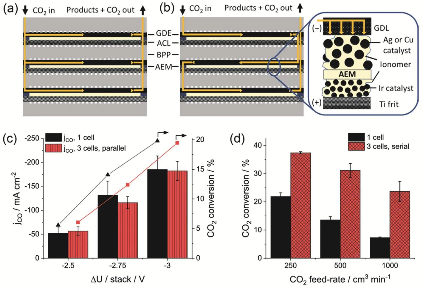
Fig. 10 A three-layer CO2 electrolyzer stack in the (a) parallel and (b) serial connection configurations. CO2RR performances in a single electrolyzer as well as a three-layer electrolyzer stack in the (c) parallel and (d) serial connection configurations. Reproduced with the permission 107. Copyright 2020, American Chemical Society.
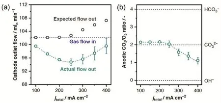
Fig. 11 (a) Actual and expected outlet gas flows from the cathodic compartment of the electrolyzer and (b) ratio of CO2 to O2 evolved over the anode as a function of current density. Reproduced with the permission 109. Copyright 2019, American Chemical Society.
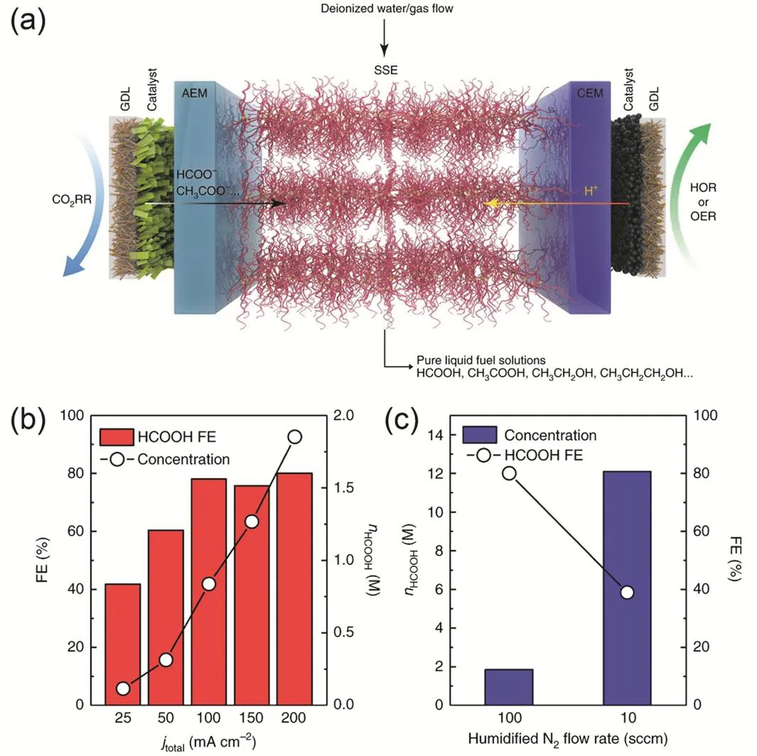
Fig. 12 (a) Schematic illustration of the CO2 electrolyzer with solid electrolyte. (b) HCOOH Faradaic efficiency and concentration as a function of applied current densities. (c) HCOOH concentration and Faradaic efficiency an overall current density of 200 mA·cm-2 as a function of N2 flow rate. Reproduced with the permission 42. Copyright 2019, Springer Nature.
The CO2crossover problem could be addressed by substituting AEMs with bipolar membranes (BPMs) consisting of an anion-exchange layer (AEL) and a cation-exchange layer(CEL)23. In most studies, the BPM is operated in a reverse bias mode in which the AEL and CEL are located at anode and cathode, respectively. However the water dissociation at the AEL-CEL interface is usually difficult even at the presence of catalysts111, leading to high cell voltage. Moreover the acidic environment near the CEL at the cathode is also unfavorable for CO2RR112. The addition of a buffer solution between the BPM and catalyst layer to sustain adequate membrane hydration is helpful to obtain high CO2RR performance112-117, but it turns into a flow-cell electrolyzer with undesired high cell voltage and low energy efficiency. The Schmidt group at the Paul Scherrer Institute has developed a MEA-cell electrolyzer using BPM operated in a forward bias mode in which the AEL and CEL are located at cathode and anode, respectively41. The CO32-/HCO3-species produced at the cathode and the protons produced at the anode react to form CO2and water at the AEL-CEL interface.While this new electrolyzer configuration achieves 200 mA·cm-2at a cell voltage of 3.3 V, CO selectivity is very low41.For both BPM configurations, the crossover of CO2is significantly reduced, but not completely eliminated especially at current densities higher than 200 mA·cm-241. Further efforts are still needed to increase the utilization efficiency of supplied CO2while maintaining high performance currently observed in AEM electrolyzers.
The crossover of liquid products from the cathode to the anode is another common experimental observation in AEM based CO2electrolyzers, caused by the electromigration of anionic products(e.g., formate and acetate) and the transport of neutral molecules(e.g., alcohols) by diffusion and electroosmotic drag39,95,107,118,119.BPMs operated in a reverse bias mode are considered to be effective in inhibiting crossover of both anionic and neutral products, as the direction of the flux of protons generated at the AEL-CEL interface opposites that of product crossover119.However this drawback of product crossover likely becomes an advantage in specific cases where concentrated liquid products are exclusively produced. Wang et al.42has demonstrated a newly-designed MEA-cell electrolyzer with modified BPMs operated in a forward bias mode. A solid-state electrolyte (SSE)being either an anion (HCOO-) or cation (H+) conductor is placed between AEM and cation-exchange membrane (CEM).The HCOO-from the cathode and H+from the anode recombine to form formic acid (HCOOH) at the CEM-SSE or AEM-SSE interfaces depending on the SSE type (Fig. 12a). Highly concentrated HCOOH (up to 12.1 mol·L-1) could be obtained in this electrolyzer when humidified N2flow is fed into the SSE layer to bring out the generated HCOOH vapor followed by cold condensation (Fig. 12b,c). However, the net CO2consumption in the process remains unclear, because in addition to HCOO-,CO32-/HCO3-anions at the cathode should travel through the AEM to the SSE and be neutralized by the protons from anode.The production of neutral alcohols in such electrolyzers42points that the positively charged protons coming from the anode must be balanced by anionic species, probably CO32-/HCO3-anions from the cathode.
7 Conclusions and perspectives
In summary, three main electrolyzers already developed for CO2RR, including H-cell, flow-cell and MEA-cell electrolyzers,have been exemplified with emphasis on their advantages and drawbacks. The state-of-the-art CO2RR performances acquired from both flow-cell and MEA-cell electrolyzers have achieved almost exclusive production of CO and formic acid (formate) at industrial current densities, but it is not yet the case for single higher-value C2+products such as ethylene and ethanol,especially in MEA-cell electrolyzers. While some issues and challenges (e.g., the crossover of CO2and liquid products, the lack of reference electrode and thus no precise potential control on the cathode) still exist, from our point of view the MEA-cell electrolyzers hold the greatest promise for practical applications after carefully analyzing current density, Faradaic efficiency,energy efficiency and stability of each electrolyzer. It should be noted that there are currently no well-accepted standard protocols regarding to the configuration and operation of CO2electrolyzers. Best practices and benchmarking measurements48,53are recommended in order to fairly compare and report CO2RR performances acquired from different labs.
In spite of such progress in CO2electrolyzers discussed in this review, it is still far away from the level of the current PEM water electrolysis. Further efforts should be input to improve CO2RR performance through rationally optimizing electrode configuration, ion exchange membrane and ionomer37,38,120,mass transfer, water management as well as process engineering,in addition to catalyst design usually focused in mechanistic studies. High pressure has shown its positive effect on enhancing CO2conversion rate and even tuning product selectivity107,116,121,122. Operation at a slightly higher te mperature (a few tens of degrees Celsius) resulting in higher reaction rate can make full use of the waste heat produced within electrolyzers by Joule effect38. Both high pressure and temperature are easily implemented in MEA-cell electrolyzers and electrolyzer stacks. These actions in process engineering are helpful to improve the single pass conversion of CO2107,122-124.As the least studied figure of merit, stability should be paid more attention in the future. In general, stability reduces dramatically with increasing the operating current densities99. Only few studies to date have shown stability tests of up to thousands of hours but at a relatively low current density37,87,99. At the end,the CO2crossover issue facing AEM-based electrolyzers should be well addressed to achieve a high CO2utilization efficiency.
From a point of view of fundamental electrocatalysis research,the information of catalyst structure and reaction intermediate extracted from in situ/operando measurements in an aqueous H-cell with low current densities might not apply to the case of flow-cell and MEA-cell electrolyzers with industrial current densities. Incorrect conclusions would be drawn if no real operando measurements were properly performed125,126. In situ/operando cells compatible with CO2electrolyzers should be developed to acquire information of catalysts and intermediates under realistic working conditions127-129. A technical challenge is to precisely control the potentials applied on the catalyst.Using a reference electrode by complex external circuit130and quasi reference electrodes by polarization curves of a couple of half reactions94have been reported, however neither of them is easy to handle especially for the compact structure of in situ/operando cells and the precision of applied potentials is still under debate.
The energy-intensive CO2RR process is partially decided by the anodic OER to a large extent. Thermodynamic analysis of CO2RR shows that a substantial portion of the overall energy is used for the OER. On the other hand the O2produced by OER is vented and not useful. Coupling CO2RR with alternative anode reactions with lower energy requirements can help lower overall electricity consumption and also produce useful chemicals at the anode. Possible alternative anode reactions include electrocatalytic conversion of biomass and low-carbon alkanes,chloride evolution as well as anodic treatments of industrial waste and environmental pollutants131-135.