Crystallography of precipitates in Mg alloys
2021-05-21ZhngZhiShiHongTingChenKeZhngFuZhiDiXueFengLiu
Zhng-Zhi Shi, Hong-Ting Chen, Ke Zhng, Fu-Zhi Di, Xue-Feng Liu
a Beijing Laboratory of Metallic Materials and Processing for Modern Transportation, Key Laboratory for Advanced Materials Processing of Ministry of Education, School of Materials Science and Engineering, University of Science and Technology Beijing, Beijing 100083, China bScience and Technology on Advanced Functional Composite Laboratory, Aerospace Research Institute of Materials & Processing Technology, Beijing 100076, China
Received 3 March 2020; received in revised form 7 May 2020; accepted 5 June 2020
Available online 7 October 2020
Abstract
Keywords: Mg alloys; Precipitation; Facet; Orientation relationship.
1. Introduction
Precipitation is an important strengthening mechanism of Mg alloys. Thermodynamically, precipitates can form in Mg matrix if the solid solubility of an alloying element decreases considerably with decreasing temperature. Such elements include Sn, Al, Zn, rare earth (RE) and so on [1-3].Fig. 1 summarizes room temperature tensile properties of age-hardenable Mg alloys reported in recent years, including Mn-Sn [4-14], Mg-Al [1,15-24], Mg-Zn [25-35] and Mg-RE[36-50] based alloys. Strain rates for tensile testing in the figur are at the magnitude of 10-3s-1. As-cast Mg alloys exhibit yield strengths (YSs) <180 MPa (Fig. 1a), ultimate tensile strengths (UTSs) <270 MPa (Fig. 1b) and elongation to failure (EL) <22%. Plastic deformation processing (i.e.,wrought fabrication) can improve both strength and ductility,while aging improves strength in sacrific of ductility. In order to obtain very high strengths without brittleness (EL>5%), aging is better to be performed after wrought fabrication, which can produce ductile Mg alloys with UTS >425 MPa (Fig. 1b) and/or YS >400 MPa (Fig. 1a). Age hardening effect originates from formation of precipitates.Precipitate shape, interfacial structure, size, volume fraction,number density and distribution affect age hardening effect.Among these microstructural factors, the former two fall in essential concerns of precipitation crystallography.
Interfaces defin the shape of a precipitate. A macroscopically sharp and fla interface is called as a facet, which can be rational (low index) or irrational (high index). At atomic scale, a facet can be fla or stepped [51,52]. Orientation of the major facet of a precipitate affects its strengthening effect noticeably [53-55]. Pinning effect of growing twin boundary reaches maximum when the habit plane (HP) of a plate-like precipitate becomes parallel to the twinning plane [54]. Based on Orowan equation, prismatic plate-like precipitates (i.e., HP//{10-10})are revealed to exert a larger yield stress increment than basal plates (i.e., HP // (0001)), c-axis rods (i.e. the long axis//[0001])and spherical particles[56,57].Crystallography of precipitates provides insight into phase transformation and gives answer to why a specificall oriented facet is preferred by nature.
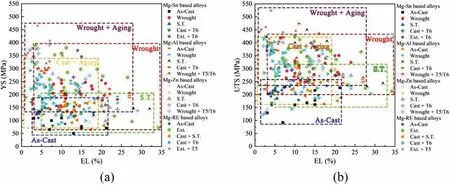
Fig. 1. Summary of room temperature mechanical properties of age-hardenable Mg alloys: (a) Yield strength (YS) and elongation to failure (EL), (b) ultimate tensile strength (UTS) and EL. Note: Wrought alloys including rolled or extruded (Ext.) ones, S.T.=Solid Solution Heat Treatment, Aging (T5=Aging without S.T. or T6=Aging after S.T.).
Although recently there are several reviews on Mg alloys[40,58,59],a comprehensive review on crystallography of precipitates is rarely to be found. Various precipitates with various shapes have been reported in Mg alloys. Although experimental results are diversified the present review will try to unify them through a theoretical view.So firs a general theory on interfacial structure will be compactly introduced, which will not go lengthy since more detailed explanations can be found in other reviews [60-62]. Then, guided by the theory,crystallography of precipitates in Mg alloys will be insightfully reviewed. The advantages of this theory and its relation with the structural ledge model, 2D invariant line model and edge-to-edge model can be found in previous reviews[61,63].At peak aging stage, Mg alloys may be strengthened by thermally stable or metastable precipitates.Since many stable precipitates have irrational facets seemingly abnormal, they will be given a prior concern.
2. A general theory of singular interface
2.1. Singular interface
Interfacial energy consists of structural and chemical components. An interface preferred by nature should locate at global/local interfacial energy minima, i.e., energy singularity. When there exists a reproducible orientation relationship(OR) between faceted precipitates and the matrix, their major facets (preferred facets) always orient in the same direction.This indicates that the energy singularity corresponds to a structural singularity [63]. Namely, any deviation from the orientation of the preferred facet will introduce at least one class of defects, including dislocations and ledges, and thus rises interfacial energy. The OR endowing the structural singularity is called as a singular OR, while ORs in its vicinity are called as vicinal ORs. If an OR can be fully define by pairs of low index directions or planes, it is called a rational OR. Otherwise, it is called an irrational OR.
Assuming α-lattice(the matrix)transforms to β-lattice(the precipitate), and the former one has smaller lattice parameters, since the precipitate often is an intermetallic phase with a much more complex atomic structure than the metallic matrix. The structural singularity is related to an ideal matching structure of the two lattices, i.e., a preferred state [60]. If the lattice parameters of the two lattices differ not much, every point in β-lattice can match a point in α-lattice and vice versa(i.e.,a one-to-one lattice correspondence),which is fully coherent and called as a primary preferred state. A famous example is Bain transformation in steels [64,65]. Otherwise,only a fraction of points from one lattice can match those in the other lattice (i.e., a n-to-m lattice correspondence, where n and m are small positive integers), which is called as a secondary preferred state, frequently found in Mg alloys [66-68].Misfi between the two lattices(i.e.,misfi in their interface)is evaluated with respect to a preferred state. Correspondingly,there are primary misfi and secondary misfi systems. The misfi is supposed to be accommodated by interfacial dislocations. Between two neighboring dislocations, the preferred state is supposed to be conserved after relaxation. Thus, an interface with structural singularity (i.e., singular interface)has a relaxed structure of periodic matching areas resembling the preferred state, separated by periodic dislocations accommodating the misfit This scenario is supported by numerous experimental observations in many alloys [61,69-71].
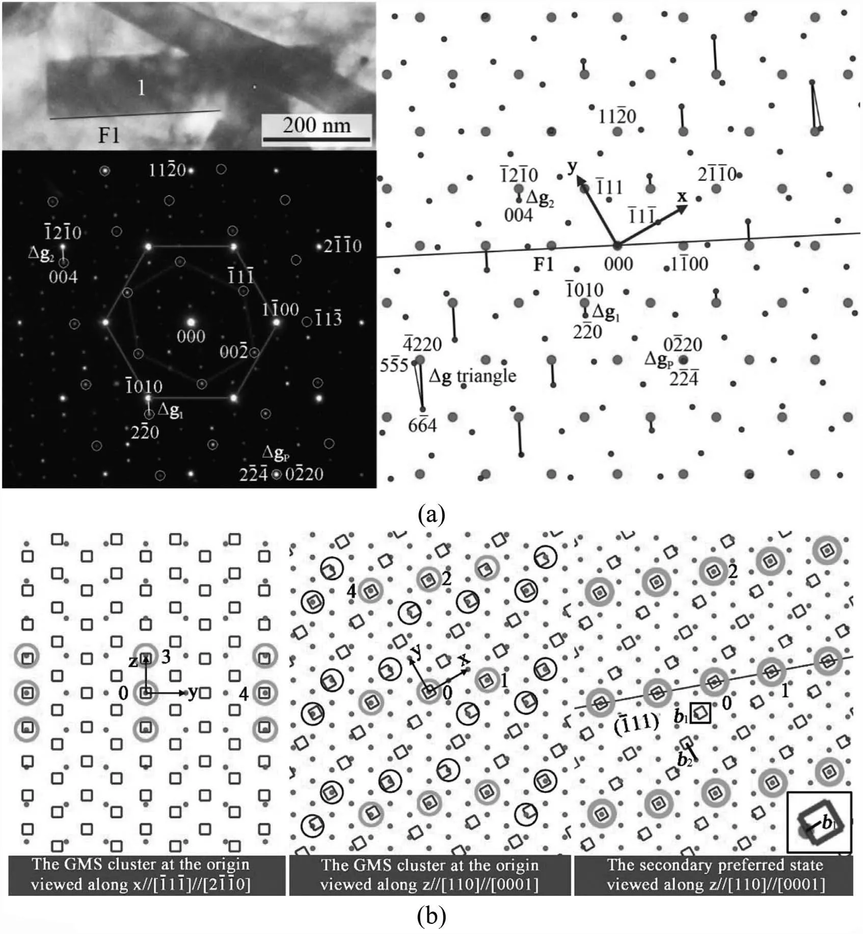
Fig. 2. An example for calculation: (a) TEM bright fiel image of a lath-like Mg2Sn particle 1 in Mg matrix with measured diffraction patterns of the two phases and simulated ones in a larger range. (b) The GMS cluster at the origin and its corresponding secondary preferred state. Dots are α-lattice points,squares are β-lattice points, and circles are GMSs. A square-shaped area is enlarged at the bottom to show a Burgers vector b1 of one set of interfacial dislocations. (c) Misfi distribution at the measured vicinal OR. (d) Misfi distribution at the calculated singular OR, deviating about -0.21° from the vicinal OR. A clockwise rotation is negative, and vice versa. Length unit in (c) and (d) is nm.
Guided by experimental characterizations, geometric modeling reveals structural singularity of interfaces in many precipitation systems [61-63,66,72]. Taking γ-Fe/α-Fe(FCC/BCC)transformation as a model system,the association of structural singularity and an energy minima is verifie by atomistic calculations of interfacial energies [62]. However,many precipitates in Mg alloys are intermetallics with complex crystal structures. For example, there are 12 atoms and 162 atoms in unit cells of Mg2Sn and Mg32(Al,Zn)49,respectively[67,73].Searching an energy minima through interfacial energy calculations is an arduous and time consuming task. It is when geometric modeling shows its power and efficien y.
2.2. The O-lattice theory
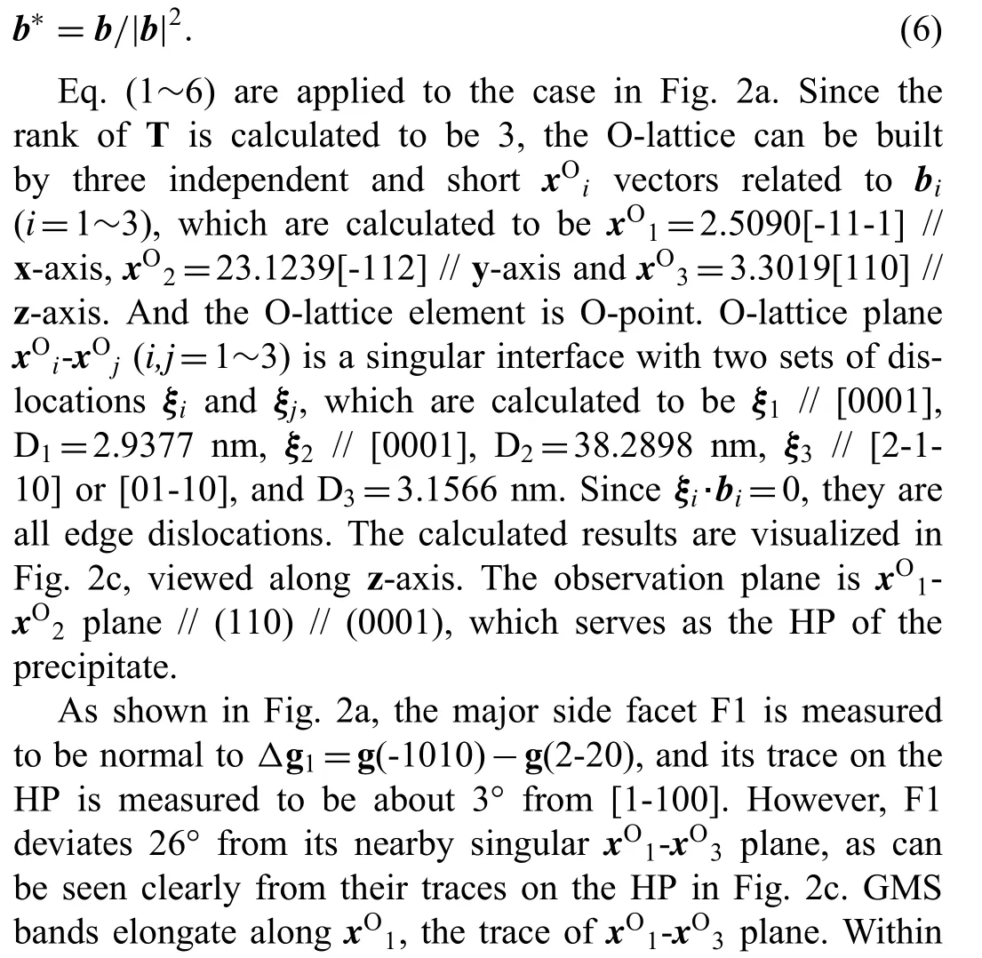
The misfi and the interfacial dislocation configuratio can be calculated based on the O-lattice theory [61,74,75]. The misfi of an O-lattice element (point, line or plane) is zero,which is the center of an area in a preferred state. An Olattice element is define by an O-lattice vector, xO. The inputs for calculating xOare: (I) lattice parameters, (II) OR,(III) lattice correspondence. For easy understanding, an example will be given together with a general calculation procedure. The exemplifie system is phase transformation from HCP Mg (α-lattice) to FCC Mg2Sn (β-lattice). The firs input, lattice parameters of Mg are aα=0.321 nm, cα=0.521 nm, and that of Mg2Sn is aβ=0.676 nm. Since aβ/aα≈2.1, the Mg/Mg2Sn system is a secondary misfi system.As shown in Fig. 2a, the second input, their OR is measured to be [-11-1] // [2-1-10], [-112] // [01-10], and [110]// [0001], where the HCP Mg phase is indexed by four indices.
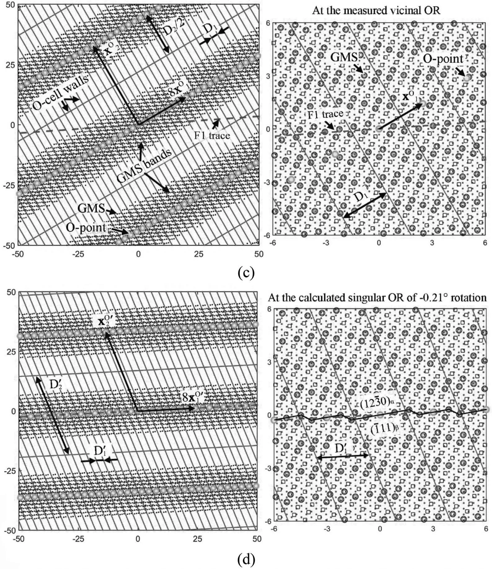
Fig. 2. Continued
The last input, lattice correspondence, is determined through good matching site (GMS) cluster [60]. When distance between two lattice points is lower than a criterion,they defin a GMS. A proper criterion is 25%aα[60]. For GMS illustration, it is a common practice to interpenetrate the two lattices at a certain OR with one point of each lattice at the origin, as shown in Fig. 2b. The frame for the figur is built as x-axis // [-11-1] // [2-1-10], y-axis // [-112] // [01-10], z-axis // [110] // [0001]. Periodicity of the GMS cluster at the origin resembles that of its corresponding secondary preferred state (Fig. 2b). Viewed along z-axis, GMSs seem to distribute randomly. Those with smaller misfit describe the periodicity, which are GMS1 with 6.6%aαmisfit and GMS2 with 6.1%aαmisfit Viewed along x-axis, the third dimension of the periodicity is clearly define by GMS3 with 13.4%aαmisfit Then,the lattice correspondence is determined by three independent pairs of vectors related respectively to GMS1(xα1=[5-4-10]/3, xβ1=[-11-2]/2), GMS2 (xα2=5[11-20]/3,xβ2=[-332]/2) and GMS3 (xα3=[0001], xβ3=[110]/2).
Transformation matrix A can be calculated by

where Xβ=[xβ1,xβ2,xβ3], Xα=[xα1,xα2,xα3], xαiand xβi(i=1~3)are column vectors.The matrix A exerts a constraint on α-lattice,forcing GMSi to be coincidence sites without any misfit Then, a constraint coincidence site lattice (CCSL) describes the secondary preferred state (Fig. 2b). Burgers vector(b) of interfacial dislocations is define by small shift vectors in the CCSL, a translation along which will not destroy the CCSL. It can be define in either of the two lattices. Here,it is done in α-lattice, i.e., the reference lattice. As shown in Fig. 2b, two Burgers vectors can be determined as b1=[2-1-10]/12 and b2=[01-10]/2. Analogously, it is easy to deduce from Fig. 2b that another independent b3=[0001]/2. Then, x°can be calculated by
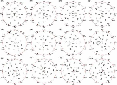
Fig. 3. Twelve ORs between Mg2Sn (FCC) and Mg (HCP). For easy differentiation, HCP Mg is indexed by four indices. For HCP lattice, [0001], <2-1-10>and <01-10>are normal to (0001), {2-1-10} and {01-10}, respectively. For FCC lattice, <uvw>are normal to {uvw}. So the poles in the subfigure can be taken as either directions or planes. For all the subfigures the horizontal direction is parallel to [11-20], the vertical direction is parallel to [-1100], and the projection direction is along [0001].

where the displacement matrix T=(I-A-1)and I is the identity matrix. Two neighboring O-lattice points are separated by an O-cell wall,which locates at where the misfi is the largest.An interface containing a xOwill intersect with a set of periodic O-cell walls. The intersection lines are a set of periodic dislocation lines. The direction (ξ) of the dislocations can be calculated by

where n is the unit normal of the interface,cOis the normal of the O-cell walls, and the operation ‘×’ means cross product.The dislocation spacing (D) is given by

The vector c° can be calculated by

where the operation ‘′’ means matrix transposition, and reciprocal Burgers vector b*is define by

2.3. From the O-lattice theory to the Δg parallelism rules
The above problem originates from a small discrepancy between the measured vicinal OR and its nearby singular OR.Exploring the relationship between O-lattice plane normal and the F1 plane normal is helpful to calculate the singular OR,which can be conveniently conducted in reciprocal space. Reciprocal O-lattice vector, x*O, can be calculated by
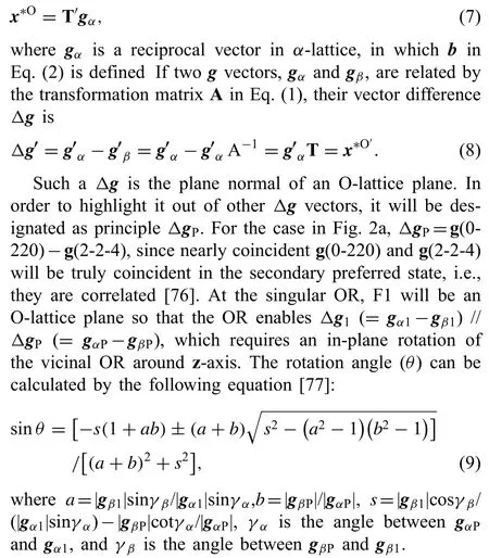
For the case in Fig. 2a, θ is calculated to be -0.2132°,where the negative sign means a clockwise rotation of βlattice and vice versa. Please refer to our paper [76] for more details. After this rotation, the vicinal OR becomes the singular OR, and a group of Δg vectors become paralleled due to linear algebra operations of Δg1and ΔgP, as drawn in Fig. 2a. Such a small rotation changes the transformation matrix A, but not the preferred state Fig. 2b) so that the Burgers vectors bikeep the same. According to Eq. (8) and ((2), it can be deduced that
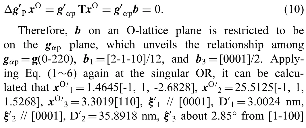
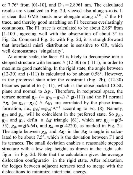
For the irrational F1, Δg // ΔgP, while for the rational HP, g // ΔgP. They are the so-called Δg parallelism rules[61], which are powerful for understanding OR, interfacial orientation and structure, especially irrational ones. In summary, Δg=gα-gβ, g // gαor gβ, where gαand gβare often low index planes, and ΔgP=gαP-gβP, where gαPand gβPare related by lattice correspondence of phase transformation.Local good matching is likely to appear in Δg plane, which is a Moiré plane [78,79]. ΔgPis an O-lattice plane, which conserves the local good matching between periodic dislocations in the whole range. The physical meaning of the rule is now quite clear, i.e., it define a singular OR, at which the interface normal to Δg // ΔgPis a singular interface at an energy minima. At atomic scale, the interface is likely to decompose into a stepped structure if a Δg triangle exists.Since the Δg parallelism rules can be conveniently checked through measured diffraction patterns, it will be employed as a clue for sorting the reported experimental data afterwards.For all the following cases, α-lattice refers to Mg matrix and β-lattice refers to a precipitate.
3. Thermally stable precipitation in HCP Mg matrix
3.1. HCP to FCC transformation
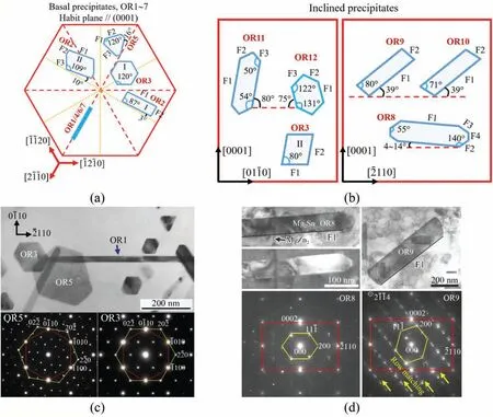
Fig. 4. Sketch summary of FCC Mg2Sn precipitates: (a) Basal ones; (b) Inclined ones. For convenience, the angles are rounded to the nearest integers. More accurate ones can be found in the manuscript. Examples: (c) OR3 type and OR5 type Mg2Sn plates observed along [111] // [0001] zone axes; (d) OR8 type and OR9 type Mg2Sn laths observed along [011] // [01-10] zone axes. Row matching is obvious in the diffraction pattern of OR9.
Crystallography of Mg (HCP, a=0.321 nm, c=0.521 nm)to Mg2Sn (FCC, a=0.676 nm) phase transformation and shape of the produced Mg2Sn precipitate show vast variety,which are worthy to be introduced firs as a paradigm for HCP/FCC system. Twelve ORs have been identifie between β-Mg2Sn and α-Mg [67]. Overlapped pole figure of the ORs are shown in Fig. 3, from which the ORs can be easily described by pairs of paralleled directions or planes. HCP Mg is indexed by four indices, while FCC Mg2Sn is indexed by three indices. Half of them are irrational ORs, one of which is OR5 [66], i.e., {111} // (0001), <1-10>about -9.2° from<-2110>. The deviation equals to a rotation around <111>//[0001]of-9.2°,which turns rational OR3 to irrational OR5.
Although Mg2Sn precipitates have many shapes (Fig. 4),their irrational major facets satisfy the Δg parallelism rule of Δg // ΔgP, as summarized in Table 1. Long ago in 1963,OR1~OR4 has been reported in aged Mg-Sn binary alloys[80]. They correspond to basal Mg2Sn precipitates (Fig. 4a)with HPs parallel to (0001). OR1 type laths grow along<2-1-10>. OR2 type plates have two shapes: (I) major facet F1 deviating about 3° from its nearest <01-10>in Mg-7Sn-2Mn alloy [76], and (II) major facet F1 deviating about 10°from its nearest <01-10>in Mg-6Sn-3Zn-0.2Mn alloy [81].F1 of OR2-I shape is the case in Fig. 2, which has stepped structure with terrace ~// (-111) ~// (12-30). However, if the stepped structure becomes fla on the terrace [81] (Table 1),F1 of OR2-II shape appears. There seems to be a dilemma between higher lattice matching and lower defect density.OR3 type particles also have two shapes: (I) hexagonal plate(Fig. 4a and c) enclosed by facets parallel to {11-2}//{-1100}[82,83], and (II) polygonal particle (Fig. 4b) with major facet F2 inclined 80° from (0001) [84]. Although both OR3 type and OR5 type plates are hexagonal-shaped viewed along[0001] zone axis, the edges of the former one are parallel to <2-1-10>, while those of the latter one deviate about 16°from their nearest <2-1-10>(Fig. 4c), which shows the use of crystallography to recognize microstructure.
By now, only Zn is revealed as an effective alloying element to turn basal Mg2Sn to be inclined ones [83,85]. In Mg-Sn-Zn based alloys, inclined precipitates (Fig. 4b) withirrational OR8~OR12 are observed [86-88]. In Mg-6Sn-3Zn-0.2Mn alloy aged at 200 °C, the majority of lath-like Mg2Sn are OR8 type laths (Fig. 4b and d) with HPs // {01-10} and major side facet F1 inclined about 4°~14° from (0001) [86].OR8 can be seen as a rotation around <011>// <01-10>of 0.36°~1.20° from OR1 (Fig. 3). The OR rotation angle can be precisely measured by taking advantage of double diffraction [86]. Viewed along [0001] zone axis in TEM, both OR8 and OR1 type laths elongate along <2-1-10>. Needle-like MgZn2precipitates(Fig.4d)with long axis//[0001]form before Mg2Sn precipitates, resulting in a T-shaped structure due to inhomogeneous nucleation of Mg2Sn at the end of MgZn2[86]. This may explain the dispersion of the OR rotation angle. In a twisted T-shaped structure, one Mg2Sn segment has F1 inclined 9.9° to (0001) with an OR rotation of 0.82°, and the other segment has F1 inclined 14.3°to(0001)with an OR rotation of 1.20° [86]. The orientation of F1 changes right at the end of MgZn2.
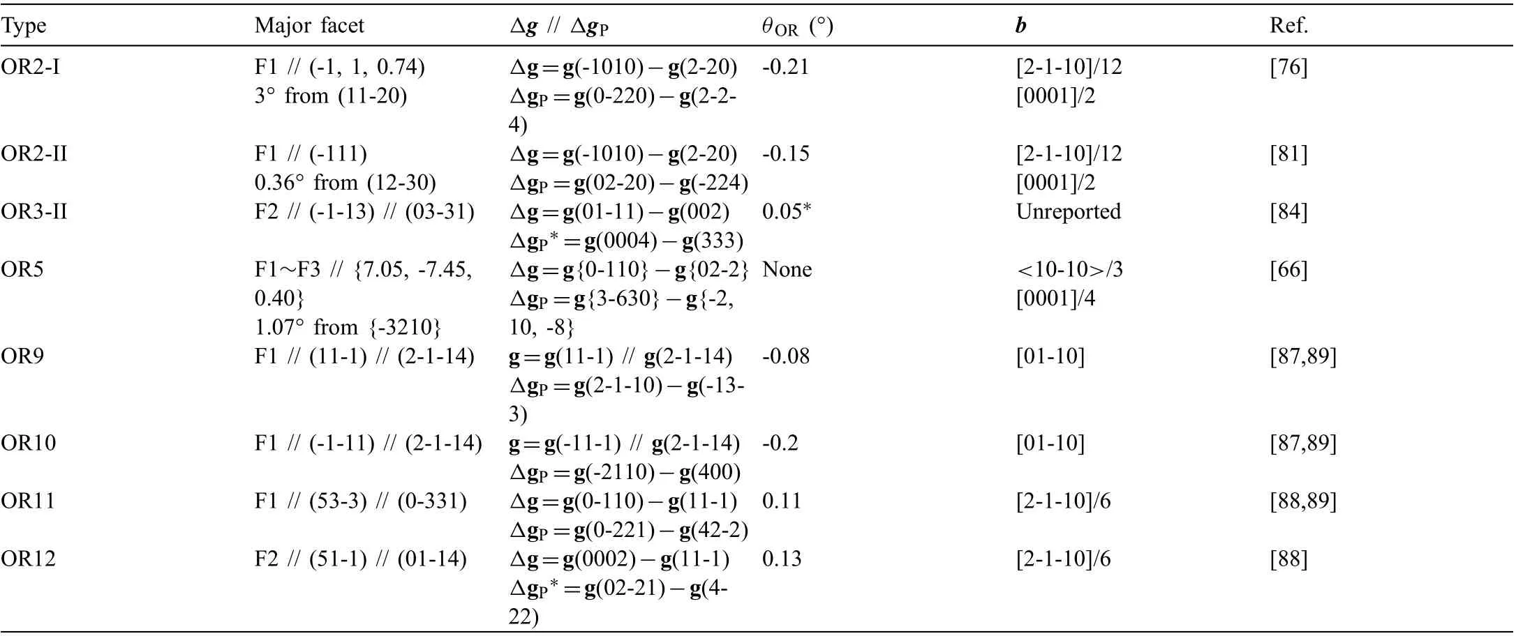
Table 1 Irrational major facets of Mg2Sn precipitates (Fig. 4) normal to Δg // ΔgP. θOR is the rotation angle required from the measured vicinal OR to the theoretical singular OR. Burgers vector (b) of interfacial dislocations is define in the reference α-lattice. The ‘*’ marked ones are calculated in the present paper.
Both OR9 and OR10 type laths (Fig. 4b and d) incline 39°from (0001) [87]. Once they have been mistakenly claimed as OR2 type laths [83]. The Mg2Sn lattices at OR9 and OR10 exhibit {11-1} twinning relationship. Through a mirror operation on (11-1) of OR9, orientation of Mg2Sn turns from OR9 to OR10. However, (2-1-14) is not a mirror plane in Mg so that OR9 is different with OR10. Although OR9 and OR10 can be expressed in a very similar way, i.e., {11-1} // {2-1-14} and <011>// <01-10>, caution should be exercised to avoid ambiguities [90]. They are better to be expressed differently as: [011] // [01-10], (100) about -15.6° from (0001)(OR9), and [0-1-1] // [01-10], (0-11) about 4.0° from (0001)(OR10). Their F1 facets satisfy two Δg parallelism rules in the meantime, i.e., g // ΔgPand Δg // ΔgP(Table 1). Thus,one set of dislocations will be canceled out, enabling the appearance of an invariant line, as the long axis of the laths[87].
The special geometry of OR9 and OR10 results in row matching of diffraction spots along g{11-1} // g(2-1-14) in reciprocal space (Fig. 4d). It is proven that there exits a oneto-one correspondence between row matchings in reciprocal and real spaces [87]. Mathematically, strict g // Δg // ΔgPrequires not only of an OR rotation, but also a small constraint on lattice parameters [89]. For both the ORs, the constrained aβc=0.675 nm [89]. The constraint is only -0.15%, small enough to be accommodated elastically. The matching row of lattice points in real space is along <011>// <01-10>. Row matching also exists in OR11 and OR12, which results in a stepped-like structure of F1 featured by a one-to-one correspondence between a terrace plane and a matching row [88].Row matching, a condition for energy minimization [91], has also been found for Al6(Mn, Fe) and S-Al2CuMg precipitates in Al alloys [92,93], TiN precipitates in Ni alloys [94], and MnZn13precipitates in biodegradable Zn alloys [95].
3.2. HCP to BCC transformation
3.2.1. Mg/Mg17Al12system
Precipitation of β-Mg17Al12(BCC, aβ=1.05438 nm) in Mg is a classical HCP to BCC phase transformation system.This is a secondary misfi system with aβ/aα≈3.3. The precipitation happens discontinuously or continuously. Discontinuous precipitation is described by α′-Mg→α-Mg+β-Mg17Al12, where Al content in super-saturated solid solution(SSSS) α′-Mg is much higher than that in α-Mg depleted with Al. Crystal structures of α′-Mg and α-Mg are nearly the same. α-Mg and β-Mg17Al12alternatively distribute, forming a cellular structure [96,97]. Differently, an eutectic reaction produces two phases with crystal structures different with that of the parent phase. The interface between α-Mg/β-Mg17Al12cell and α′-Mg is in fact a Mg grain boundary,across which chemical composition changes discontinuously.In atomic scale, discontinuous Mg17Al12precipitates have a straight interface with regular dislocations within the Mg side or a stepped interface with (-112) as terrace and (21-1) as ledge [51]. Discontinuous precipitation adversely impacts on mechanical properties of Mg-Al alloys.

Table 2 Reported ORs between BCC precipitate and HCP Mg matrix. HCP Mg is indexed by four indices, while BCC phase is indexed by three indices. OR1~OR8 are observed for Mg17Al12 precipitates. OR9~OR11 are observed for Mg32(Al, Zn)49 precipitates.
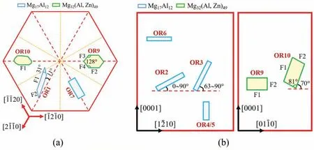
Fig. 5. Sketch summary of BCC precipitates: (a) Basal ones or non-basal ones viewed along [0001]; (b) Non-basal ones.
Continuous precipitation is described by α′-Mg→β-Mg17Al12. The precipitate nucleates within Mg grains, and chemical composition changes continuously in Mg matrix surrounding it. Endeavors have been made to promote continuous precipitation and suppress discontinuous precipitation through adjusting aging temperature and further alloying[98-100]. The reported ORs between continuous Mg17Al12precipitates and Mg matrix are summarized in Table 2. OR1 type Mg17Al12is the most famous and frequently observed[101-104]. Its shape evolves with aging time. In AZ91 alloy aged at 200 °C, it is small lozenge-shaped plate when <1 h, then grows to be an asymmetric-lozenge shaped plate(Fig. 5a) with aspect ratios (length/width) of 3~5 at 2~9 h,and finall grows to be lath-like with an aspect ratio of 25 at 16 h[105].The asymmetric-lozenge shape is define by HP//{011}//(0001),major side facet F1//{43-3}and minor facet F2 // {12-30} [96]. Its thickness grows only 45 nm in 15.5 h, much slowly than its length and width, due to low energy interfaces HP and F1. The facet F1 satisfie the Δg // ΔgPrule [106], where Δg=g(1-100)-g(0-33) and ΔgP=g(02-20)-g(63-3). The rule requires a rotation of 0.54° around[011] // [0001], agreeing well with the measured rotation of 0.5°. The F1 has a stepped-like structure with (21-1) or (01-10) as the terrace and two sets of secondary edge dislocations(ξ1=[011],b1=[2-1-10]/6,D1=3.8 nm,and ξ2=[1.6,-1,1],b2=[0001], D2=12.5 nm) [106]. The ξ2dislocations and the steps have a one-to-one correspondence.
Conventional selected area diffraction (SAD) technique is insensitive to about 2°rotation of OR2 from OR1.More accurate Kukuchi line diffraction technique reveals that OR1 and OR2 equally appear in AZ91 alloy aged at 350 °C for 6 h[112]. HPs of OR2 are more complicated, which are parallel to within 20° of (10-11), (-1-230) or (0001) [112]. OR3 and OR4 type laths exhibit HPs // {011} // {-1010} [112]. As shown in Fig. 5b, OR3 type lath inclines to (0001) in AZ91 alloy aged at 200 °C, while it is perpendicular to (0001) in AZ91 alloy aged at 350 °C [105,112]. OR4 and OR5 type laths with HPs // {-1010} are perpendicular to (0001) [113].In AZ91 alloy aged at 200 °C for 8 h, OR6 type basal lath is much shorter than OR1 type basal lath, viewed along [1-100]zone axis [108]. However, the former one is not observed along [0001] zone axis, so that the direction of its long axis is not identified OR7 and OR8 are reported on individual precipitates, frequencies of which are unclear. OR8 type particle is irregular shaped without sharp facets [51].
3.2.2. Mg/Mg32(Al, Zn)49system
Three new ORs of HCP/BCC system, i.e., OR9~OR11 in Table 2, are identifie between Mg32(Al, Zn)49(BCC,aβ=1.416 nm) precipitate and Mg matrix firs in Mg-6Zn-5Al alloy aged at 180 °C. The phase is also detected in other Mg-Zn-Al based alloys [114-117]. This is a secondary misfi system with aβ/aα≈4.4. OR9 type precipitate is polygon-shaped (Fig. 5) define by facets F1 // {010} //(0001), F2 // {100} // {01-10}, F3 // {70-9} // {5-610},and F4 // {709} // {51-60} [68]. The relative sizes of the facets vary for the precipitates. Either F1 or F2 can be the largest facet, or the four facets can be comparably large[110,111]. Irrational symmetrical facets F3 and F4 are normal to Δg3-1=g(1-100)-g(-305) and Δg4-1=g(10-10)-g(305),respectively [68]. OR10 type precipitate (Fig. 5) has a capped parallelepiped shape inclined 70° to (0001). Its facets F1 and F2 are normal to Δg1=g(0001)-g(-130) and Δg2=g(01-1-1)-g(5-30), respectively [68]. Viewed along [012] //[2-1-13] zone axes, OR11 type precipitate is hexagon-shaped[111]. Further research is required to determine its 3D shape.
3.3. HCP to BCO transformation
Ag addition in Mg alloys can lead to precipitation of Mg54Ag17(body-centered orthorhombic, BCO, aβ=1.4240 nm, bβ=1.4209 nm, cβ=1.4663 nm) [118,119]. Its lattice parameters are close to that of BCC Mg32(Al, Zn)49. This is a secondary misfi system with bβ/aα≈4.4. The majority of Mg54Ag17precipitates resemble OR9 type Mg32(Al, Zn)49(Table 2) not only in OR but also in shape. Analogously, their shape is define by four facets, i.e., F1 // (001) // (0001), F2// (010) // (-1100), F3 // (-14, 11, 0) and F4 // (14, 11, 0).The irrational facets F3 ⊥Δg3-1=g(10-10)-g(5-30) and F4⊥Δg4-1=g(01-10)-g(530) are symmetrical with respect to F2. The acute angle between F3 and F4 is 77°, close to that of 76° between those of Mg32(Al, Zn)49(Fig. 5a). Growth twin forms in Mg54Ag17precipitate. The twin exhibits an irrational OR of (00-1) // (0001) and [100] about 6.9° from[10-10] with Mg matrix [120].
4. Metastable precipitates
Precipitation sequences in Mg alloys have been summarized in a previous review published in 2012 [121]. The present paper focuses on recent progresses. Metastable precipitates are recently identifie in Mg-9.8Sn alloy aged at low temperatures below 160 °C [122]. The precipitation sequence is: SSSS Mg→GP zone→β′-Mg3Sn (Pm-3m, a=0.453)→OR2 type β-Mg2Sn. It is unclear whether other types of Mg2Sn precipitates (Fig. 3) have precursors or not.Classical Mg-Zn and Mg-RE alloy systems are dealt in the following subsections, since their experimental results are relatively abundant.
4.1. Mg-Zn alloys
A series of phase transformations involve in aging of Mg-Zn alloys. The aging products sequentially form as follows [121,123-125]: SSSS Mg→GP zones→β′1(Mg4Zn7or MgZn2)→β′2(MgZn2)→β (MgZn or Mg2Zn3). The GP zones have two types.GP1 zones form below 60°C are plates on {11-20}, while GP2 zones form below 80 °C are oblate spheroids on (0001) [125]. Aging peak attributes primarily to rod-like β′1growing along [0001]. Over the aging peak, β′2increases in sacrific of β′1with time.
Controversy has existed for rod-like β′1. In Mg-6Zn based alloys aged at 160 °C, Mg-5Zn-2Gd-0.4Zr alloy aged at 200°C and so on, β′1is claimed to be MgZn2with a HCP structure (a=0.522 nm, c=0.857 nm) [119,124,126,127]. However, in Mg-8Zn alloy aged at 200 °C, β′1is claimed to be Mg4Zn7with a base-centered monoclinic structure (BCM,a=2.596 nm, b=1.428 nm, c=0.524 nm, γ=102.5°)[128,129]. First-principle calculations suggest that the relative stability of the two phases depends on their compositions and temperature, implying either one or both of them can exist within β′1[130]. Indeed, the coexistence has been observed in aged Mg-Zn(-Y) alloys [131,132].
The OR between β′1-Mg4Zn7rod and Mg matrix is<001>// [0001], and {630} // {01-10} (OR-A) [128], while that between β′1-MgZn2rod and Mg matrix is <2-1-10>p// [0001] and [0001]p// <2-1-10>(OR1 in Table 3) [126].To differentiate two HCP structures, precipitate is marked by the subscript ‘p’. For precipitates with MgZn2and Mg4Zn7domains, ORs are [0001]p// <010>// [0001] and {0-110}p// {20-1} // {11-20} [128]. The long axis of rod-like β′1can be well explained by lattice matching. For β′1-Mg4Zn7, the misfi between [001] and [0001] is 0.93%aα. For β′1-MgZn2,the misfi between [2-1-10]MgZn2/3 and [0001] is 0.31%aα.Both of the misfit are very small. Thus, [0001] is a low energy direction, preferred as the long axis. Blocky β′1-Mg4Zn7inclined about 11° to (0001) is also observed, which exhibits another OR of <001>// <10-10>and {250} // (0001) (ORB) with Mg matrix. The inclination has not been explained yet.
β′2precipitate is MgZn2with several shapes and ORs.OR2 type β′2-MgZn2(Table 3) is hexagon-shaped with HP// (0001) and side facets // {-1010} [128]. OR3 type β′2-MgZn2(Table 3) is rod-like with a major facet about 6° from its nearest {10-10} plane [128], which has not be explained yet. Other three irrational ORs [123] are seldom confirme so that they are not listed here.
4.2. Mg-Nd alloys
Precipitation sequence of all the possible aging products in Mg-Nd alloy is: SSSS Mg→Nd-rich clusters→GP zones→β′′′→β′(β′F)→β3→β2→β1→β →βe, as summarized in Fig. 6. In the early stage, Nd-rich clusters havevarious configurations including single column,two columns,V shape, N shape (zig-zag) and hexagonal ring (Fig. 6a).Possibly because the latter three shapes already have a 2D pattern, they are called as GP rods in the paper [136]. Clusters of two columns, V shape, N shape periodically arrange into monolayer GP zones [135]. Two examples are given in Fig. 6b. The GP zones elongate along <2-1-10>or deviating from it about 11° [137]. Zig-zags and hexagonal rings together construct β′′′phase (Fig. 6c). It contains building blocks of orthorhombic β′and D019β′′phases. Although β′′phase has not yet been verifie in Mg-Nd alloys through any high-angle annular dark-fiel scanning TEM (HAAF-STEM)observations, stacking defects along [0001] endow the projection of two adjacent β′′′plates a D019structure [136], as shown in Fig. 6c. Until now, the aging products are coherent with Mg matrix, among which β′′′and β′(Fig. 6d, also designated as β′F) on {2-1-10} have developed 3D structures and large enough to have facets [137,141].

Table 3 Reported ORs between HCP precipitates (subscript ‘p’) and HCP Mg matrix.
The ahead sequence of β′→β1→β →βe(Fig. 6e) has been well established for a long time. However, between β′and β1two transitional phases β3and β2are identifie recently [139,140]. The former one appear frequently at ends of β1rods,while the latter often connects two{-1100} β1plates of the same variant or two variants with opposite shears.With the lattice parameters and ORs provided in Fig. 6e, it can be deduced that good matching achieves along: (I) [0-10]β3(=1.8047 nm)//2<1-100>β2(=1.8117 nm)//<-112>β1(=1.8126 nm), (II) 2[0001] (= 1.042 nm) // [100]β3(= 1.042 nm) // 2<11-20>β2/3 (= 1.046 nm) // <110>β1(= 1.047 nm), (III) <11-20>(= 0.963 nm) // [001]β3(= 0.961 nm)// [0001]β2(= 0.963 nm), and 4<11-20>/3 (= 1.284 nm) //<1-11>β1(= 1.282 nm). So (001)β3// (0001)β2// {1-11}β1and {-1100} // (0-10)β3// {1-100}β2// {-112}β1are two sets of good matching planes, which explains the observed coherent interfaces between the transitional phases and their major facets in Mg matrix. β and βedo not arose much interests since their appearances accompany considerable over aging,and thereby low strengths.
5. Theoretical advances on precipitation crystallography
5.1. Secondary constrained coincidence site lattice(CCSL-II) model
Due to freedom limitation of OR, the Δg parallelism rules alone fail to explain the shapes and the ORs of Mg32(Al,Zn)49and Mg54Ag17precipitates with symmetrical irrational facets. Thus, the secondary constrained coincidence site lattice(CCSL-II)model is developed[142],which has explained crystallography of several precipitates in Mg alloys, including Mg32(Al, Zn)49, Mg54Ag17, Mg2Sn, Mg17Al12, and Mg2Y[70,71,120,143-146]. Representative examples are given in Fig. 7a. Although CCSL-II model is at firs developed to explain symmetrical irrational facets [142], its application has been extended to asymmetrical irrational facets (e.g.Mg/Mg2Sn system [71]) and symmetrical rational facets (e.g.Mg/Mg2Y system [145]). CCSL-II is constructed by the following steps:
(I) Construction of a secondary preferred state as introduced in Section 2.2. Its related CCSL will be called as conventional/primary CCSL (CCSL-I) afterwards.
(II) Description of lattice misfi distribution by the O-lattice theory in Section 2.2.
(III) Construction of CCSL-II.
Except at the origin, an O-lattice point rarely coincides with a GMS, unless the lattice parameters of the two phases are very special. So the GMS cluster with CCSL-I pattern at the origin (e.g., in Fig. 2b) will lose its integrity far away from the origin. A very small strain define by matrix AIIIcan make central GMS of each GMS cluster to be an Olattice point, resulting in CCSL-II. Please refer to our paper[66] for AIIIcalculation. Then, GMS clusters of CCSL-I pattern can realize a periodic distribution in CCSL-II (Fig. 7b and c) and more than one irrational facets now obey the Δg parallelism rules simultaneously. The CCSL-II strain is much smaller than the CCSL-I strain. So the former one is likely to be accommodated elastically. HRTEM characterizations in Mg/Mg54Ag17system provide concrete evidence of CCSL-II[70].
Interfaces with high density (dII) of CCSL-II sites and low step height (hstep) are candidates of preferred facets. For OR9 type Mg32(Al, Zn)49in Fig. 7a and b, closely packed CCSLII planes can be ranked with decreasing dIIvalues as F1 >F3=F4 >F2 >F5,among which F1,F2 and F5 are step-free[143]. The step heights of F3 and F4 are equivalent to the planar spacing of {101}, i.e., hstep=1.0 nm. The observed facets are F1~F4. Their relative sizes vary due to kinetic factors (Fig. 7b). For OR5 type Mg2Sn in Fig. 7a and c,closely packed CCSL-II planes can be ranked with decreasing dIIvalues as F4 >F1=F2=F3 >F5, among which only F4 is step-free[66].The step of F5 is too high to be energetically favorable. The observed facets are F1~F4, among which F4 is the HP.
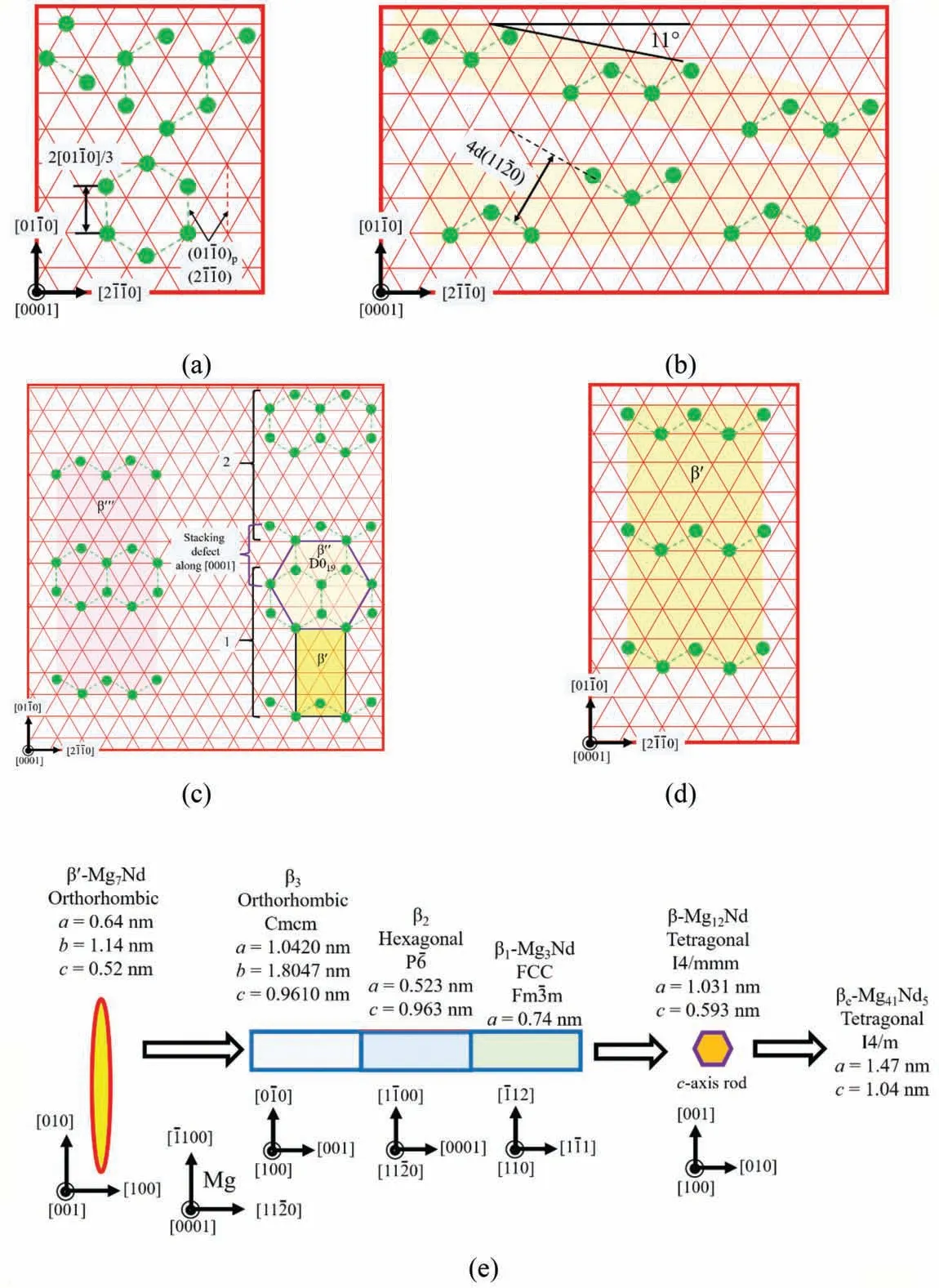
Fig. 6. Sketch summary of aging products verifie by HAAF-STEM observations in Mg-Nd binary alloy: (a) Nd-rich clusters (or GP rods) [135,136], (b) GP zones [135-137], (c) β′′′ [136,137], (d) β′ (or β′F), (e) from β′ to βe [121,138-140].
5.2. Near row matching (NRM) approach
It is an everlasting pursuit to predict preferred interfaces and ORs between two phases in a high-throughput way. A quick search of possible candidates of preferred interfaces and ORs according to structural singularity is physically meaningful and feasible. Mg/Mg2Sn system with twelve ORs(Fig. 3) is suitable to serve as a touchstone of any predictive model. Recently, a near row matching (NRM) approach is developed [148].
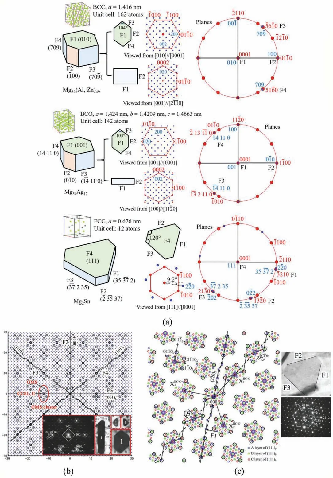
Fig. 7. Application of CCSL-II model: (a) Summary of precipitates with irrational facets and their related rational or irrational ORs well explained, based on experimental data collected from references [66,68,70]. Pole figure and diffraction patterns are plotted by using free and open-source software PTCLab[147]. (b) Lattice matching between OR9 type Mg32(Al, Zn)49 precipitates and Mg matrix [143]. (c) Lattice matching between OR5 type Mg2Sn precipitates and Mg matrix [66].
It is common that GMS clusters periodically distribute on singular interfaces. Inspired by this, NRM approach [148] is proposed to search candidates of preferred interfaces and ORs in a secondary misfi system, based on two-dimensional(2D) GMS clusters permitted by row matching. The approach works through two steps. Step one it to fin a matching row contains GMS segments (clusters in 1D). Step two is to fin matching in rows parallel to the matching row, ensuring 2D GMS clusters. The plane contains the paralleled matching rows is a candidate of preferred interface. The plane normal and the row matching direction fi the OR. An application of this approach to Mg/Mg2Sn system shows its effectiveness[148].
6. Summary and outlook
Hardness peaks of age-hardenable Mg alloys attribute to precipitation of thermally stable or metastable phases. Either of them often shows reproducible crystallographic features.For a precipitate with one irrational major facet, the dislocation structure of this facet and its related OR can be explained through a well developed methodology combined of the Olattice theory and the Δg parallelism rules. However, due to freedom limitation of OR, difficult lies in explaining a precipitate with several irrational major facets. CCSL-II model is then developed,which explains Mg32(Al,Zn)49and Mg54Ag17with two symmetrical irrational facets for each, and OR5 type Mg2Sn basal plate with three symmetrical irrational facets.The model also extends to precipitates with asymmetrical irrational facets or rational facets. It is worthy to mention that Mg32(Al, Zn)49and Mg54Ag17have almost identical shapes,although their chemical components and atomic structures are considerably different. This is an evidence of the correspondence between structural singularity and low energy, which enables a quick prediction of ORs through geometric NRM approach. The following aspects are worthy to be paid attention in future:
1. How pre-existing twin boundaries affect crystallography of precipitates. This is unclear for many kinds of precipitates and twins. Both twin boundaries and precipitates are obstacles of dislocation motion and thus strengthen Mg.Twin boundary migration, e.g., twin annexation and detwinning,may be pinned or dragged by precipitates, which will stabilize twin boundaries and thereby their strengthening effect. Twin boundary induced precipitate variant selection requires more investigation, which is important for microstructure prediction. Due to low critical resolved shear stress (CRSS), {10-12} twins can easily form and grow in Mg alloys, resulting in a larger degree of grain refine ment than other twin types and therefore worthy for a prior concern. Sequential biaxial loading can introduce much more {10-12} twin boundaries than conventional uniaxial loading [149,150]. This provides a better environment for studying twin-precipitate interaction. Strain field around twin boundaries attract alloy elements, which may lead to formation of novel precipitates other than that in the aforementioned Mg-RE based alloy.
2. How a pre-formed precipitate affects crystallography of its connective follower. This is simpler for metastable precipitates in Mg-RE alloys, in which precipitate/precipitate and precipitate/Mg interfaces are (nearly) coherent and the interfacial orientations as well as their related ORs are rational. This owes largely to their special ratios of lattice parameters. Otherwise, things will be more complicated,giving rise to irrational ORs and facets. The major facet of a new precipitate is likely to be altered by the presence of an old-precipitate/Mg interface. The fina OR between the new precipitate and Mg may not be the same with the initial OR, since the old-precipitate/new-precipitate interface plays a vital role in initial stage.
3. Incorporate experiments, geometrical models and atomistic simulations to systematically investigate precipitation sequence and transformation crystallography. In the past,most studies focused on experimental measurements and/or geometrical models. Though great progresses have been achieved, there are still many unknowns related to precipitation,e.g.interfacial energies of facets,relative preference of different ORs, segregation of alloy elements around interfaces, and etc. Atomistic simulations are good complementary to experiments and geometrical models to solve these problems.However,except for calculating fundamental properties of precipitate phases, atomistic simulations have rarely been adopted to evaluate precipitation transformation. The main obstacle in applying atomistic simulations is probably the lack of reliable potential, which can well predict the properties of so many phases, including the Mg matrix and sequential precipitated phases. With the development of machine learning potentials, the dilemma of potential lacking can be solved. It is hopeful that atomistic simulations will play an import role in understanding precipitation crystallography in near future.
Declaration of Competing Interests
None.
Acknowledgement
Financially supported by the Fundamental Research Funds for the Central Universities (Project FRF-TP-19-022A3Z)and National Natural Science Foundation of China (Project 51771022). Advices from Prof. Wen-Zheng Zhang in Tsinghua University are appreciated.
杂志排行
Journal of Magnesium and Alloys的其它文章
- Mechanism of Mn on inhibiting Fe-caused magnesium corrosion
- An efficien and comparative adsorption of Congo red and Trypan blue dyes on MgO nanoparticles: Kinetics, thermodynamics and isotherm studies
- Twin recrystallization mechanisms in a high strain rate compressed Mg-Zn alloy
- Corrosion behaviour and cytocompatibility of selected binary magnesium-rare earth alloys
- Correlation between test temperature, applied load and wear transition of Mg97Zn1Y2 alloy
- Residual stress and precipitation of Mg-5Zn-3.5Sn-1Mn-0.5Ca-0.5Cu alloy with different quenching rates
