Axial acoustic radiation force on an elastic spherical shell near an impedance boundary for zero-order quasi-Bessel–Gauss beam∗
2021-05-06YuChenZang臧雨宸WeiJunLin林伟军ChangSu苏畅andPengFeiWu吴鹏飞
Yu-Chen Zang(臧雨宸), Wei-Jun Lin(林伟军),†, Chang Su(苏畅), and Peng-Fei Wu(吴鹏飞)
1Institute of Acoustics,Chinese Academy of Sciences,Beijing 100190,China
2University of Chinese Academy of Sciences,Beijing 100049,China
Keywords: acoustic radiation force,zero-order quasi-Bessel–Gauss beam,impedance boundary,elastic spherical shell
1. Introduction
The acoustic radiation force, arising from the momentum transfer between sound waves and scattering objects,has been a hot topic due to its potential applications in acoustic tweezers,[1–5]acoustic levitation,[6,7]and particle manipulation.[8–10]Since King[11]first set forth the concept of acoustic radiation force on particles and calculated the force experienced by a rigid sphere in travelling and standing wave field, there have been many relevant theoretical and experimental studies till now. A large number of these studies are concerned with the radiation force acting on spherical objects as well as the determination of the acoustic intensity through measuring the radiation force. Yosioka et al.[12]first developed a theory for the acoustic radiation force acting on a compressible sphere. Hasegawa et al.[13]successfully calculated the radiation force on an elastic sphere, showing that both the compressive and shear wave velocities play critical roles in determining the radiation force. Shortly after, they presented an analytical expression of acoustic radiation force on a sphere in a quasi-stationary field.[14]With the development of beamforming and ultrasonic transducer technology, Wu &Du[15]first considered the radiation force in a focused Gauss beam field, laying the foundation of developing single beam acoustic tweezers. A single beam acoustic tweezer for threedimensional(3D)trapping in a vortex beam was also presented by Baresch et al.,[16]which can selectively pick and control the position of a particle in three dimensions as well as achieve the controlled rotation of absorbing particles. Marston[17–20]and Mitri[21–28]systematically investigated the acoustic radiation force acting on a sphere exerted by both zero-order and high order Bessel beams.In recent years,considering the commonness of the spheroidal objects in actual practices such as the suspended droplets in air,some researchers have extended their scope of study to the spheroids in Bessel beams.[29–32]
Based on all of these results, there is a growing interest among researchers to consider the acoustic radiation force on small particles near an impedance boundary instead of an unbounded field. Actually, the particle manipulation in practice are often performed in a bounded field especially in many biomedical applications. Miri et al.[33]added a vessel porous wall to the single spherical contrast agent shell and analyzed the effect of the impedance boundary on acoustic radiation force in detail. Wang et al.[34]theoretically and numerically studied the acoustic radiation force exerted by a standing wave on a rigid cylinder near a flat wall. Qiao et al.[35,36]developed a model to work out the acoustic radiation force acting on a fluid cylinder near an impedance boundary using the image theory. More recently,the same authors extended the research to the elastic cylinder case.[37]Analyses of the acoustic radiation force on a fluid sphere between two impedance boundaries were also performed by our group.[38]
It is well known that micro-shells have been utilized by many researchers for drug and gene delivery systems.[39–41]Due to its non-immunogenity and noninvasiveness, the ultrasound-mediated microbubble system has drawn wide attention from researchers in both the diagnostic and therapeutic applications of ultrasound contrast agents. To safely and accurately guide the contrast agent micro-shells towards the desired targeted positions,it is important to make clear of the mechanism of acoustic radiation force acting on this kind of structure. Hasegawa et al.[42]solved the acoustic radiation force exerted on both cylindrical and spherical shells in plane progressive waves. Later, Mitri[43,44]extended this theory to the case of elastic and viscoelastic spherical shells in plane standing waves, in which the sound absorption effect inside the elastic material was systematically studied. Based on the results in earlier works,our group also presented a theoretical model to compute the radiation force on a multilayered elastic shell in standing Bessel beams.[45]
As a typical type of non-diffracting beams,Bessel beams have both the property of narrow beam-width and large depth of field, thus they have many potential applications in ultrasonic imaging and other fields. Given an infinite aperture, a zero-order Bessel beam can travel to infinity without changing its profile and amplitude. However, the aperture sizes of the beams are always finite, therefore only within the depth of field is the fundamental Bessel beam viewed as non-diffracting. With the radial profile given by Bessel–Gauss function, Bessel–Gauss beams can be seen as the simplest case of the physically realizable finite aperture Bessel beams.In 2003, the axicon-based Bessel–Gauss resonator with concave output coupler was firstly developed in optics.[46]Later,a simple and compact source was created by researchers to directly produce a Bessel–Gauss beam.[47]Since then,the nondiffracting property of Bessel–Gauss beams has been used to generate low-order harmonics in gas.[48]As for its applications in acoustics, the properties of the fundamental and second harmonic components were studied by Ding et al.[49]Some approximate analytical descriptions were also investigated with a finite aperture.[50,51]In 2017,Chen et al.[52]first combined the study of acoustic radiation force with quasi-Bessel–Gauss beams, theoretically figuring out the radiation force on a sphere in a progressive and standing zero-order quasi-Bessel–Gauss beam. They found that the energy concentration of Gauss component can make up for the shortfall of the relatively small amplitude of acoustic radiation force in Bessel beams.However,to the best of our knowledge,no work has been done dealing with the acoustic radiation force near a boundary in this case.This study aims to extend Chen’s results to a bounded space,providing a closed-form expression of the acoustic radiation force on an elastic spherical shell near an impedance interface for zero-order quasi-Bessel–Gauss beam.This model can be taken as the simulation of a contrast agent besides the human blood vessel wall. Admittedly, a cluster of micro-shells are more likely to be used in drug-loaded ultrasound applications. However, the study on a single shell serves as a necessary interim step to deepen our understanding of the radiation force effect. Also, a proper estimation of the radiation force is of great significance to avoid the shell’s fragmentation and attachment to the blood vessel wall. Some numerical simulations are also carried out with particular emphasis on: (i) the effects of the impedance boundary; (ii) the effects of the shell’s thickness; (iii) the half-cone angle and beam waist of the incident beam;(iv)the fluid medium filling the hollow space; (v)the viscosity of the coated elastic layer.For purposes of this study,it is assumed that the amplitudes of both the sound pressure and particle velocity are so small that the nonlinear wave propagation effects can be neglected.
2. Theory
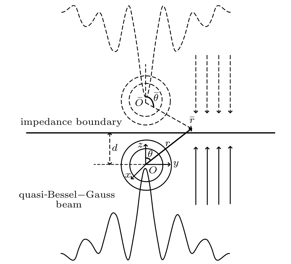
The geometry of this problem is shown in Fig.1.A spherical shell of outer radius a and inner radius b is positioned in a non-viscous fluid and at distance d from the impedance boundary. The center of the shell coincides with the origin of both the Cartesian coordinate system(x,y,z)and the spherical coordinate system (r, θ, φ). From the geometric relationship between two systems, we can conclude that x=rsinθ cosφ,y=rsinθ sinφ, z=rcosθ. Let a zero-order quasi-Bessel–Gauss beam be incident upon the shell along the+z direction,which is perpendicular to the impedance boundary. As a complex solution of the paraxial equation, the standard Bessel–Gauss beam has been studied by previous researchers in detail,which features the non-diffracting advantage of Bessel beams and the energy focusing property of Gauss beams.[53,54]

2.1. Expansion of incident beam in terms of spherical functions
Assume that the field distribution at the waist of a zeroorder quasi-Bessel–Gauss beam is given by
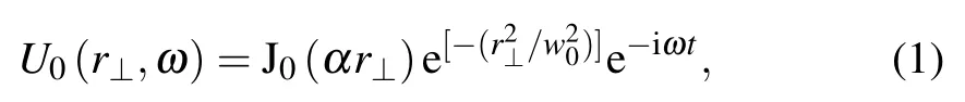
where ω is the angular frequency of the incident beam,α and w0are two constants, r⊥=rsinθ is the radial distance from the axis of the beam,and J0denotes the zero-order cylindrical Bessel function. We can imagine it as a Gauss beam “modulated” in amplitude by the Bessel function, or a zero-order Bessel function weighted by the Gaussian aperture. The two parameters α and w0determine the effective width and aperture of a zero-order quasi-Bessel–Gauss beam, respectively.Obviously, the zero-order Bessel beam and the Gauss beam are special cases of the zero-order quasi-Bessel–Gauss beam.It will degenerate into a basic Gauss beam when α approaches zero and will degenerate into a basic zero-order Bessel beam when w0approaches infinity. Substituting Eq. (1) into the Fresnel propagation formula,we can obtain the mathematical expression of the beam field at distance z as follows:[47]
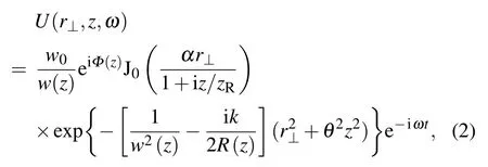
where k=ω/c0is the wave number in the fluid medium, c0is the compressional wave speed in the surrounding fluid, zRis the Rayleigh range, Φ(z)=kz −α2z/2k −arctan(z/zR), is the axial phase of the beam. Moreover,the spot size w(z)and the wave front curvature R(z)are the same as those for a basic Gauss beam.
Strictly speaking, a quasi-Bessel–Gauss beam does not possess the non-diffracting property. In other words,the radial distribution depends on the propagation distance, which can be easily seen from Eq.(2). However,it can be approximated to be non-diffracting in the region near the focal plane. Based on this premise,we express the local approximation for the velocity potential of a quasi-Bessel–Gauss beam near the focal region at z=0 as[52]

where φ0is the amplitude of the velocity potential,kz=kcosβ and kr=ksinβ are the axial and radial wave numbers,β is the half-cone angle of the Bessel beam component and W0is the beam waist of the Gauss beam component.

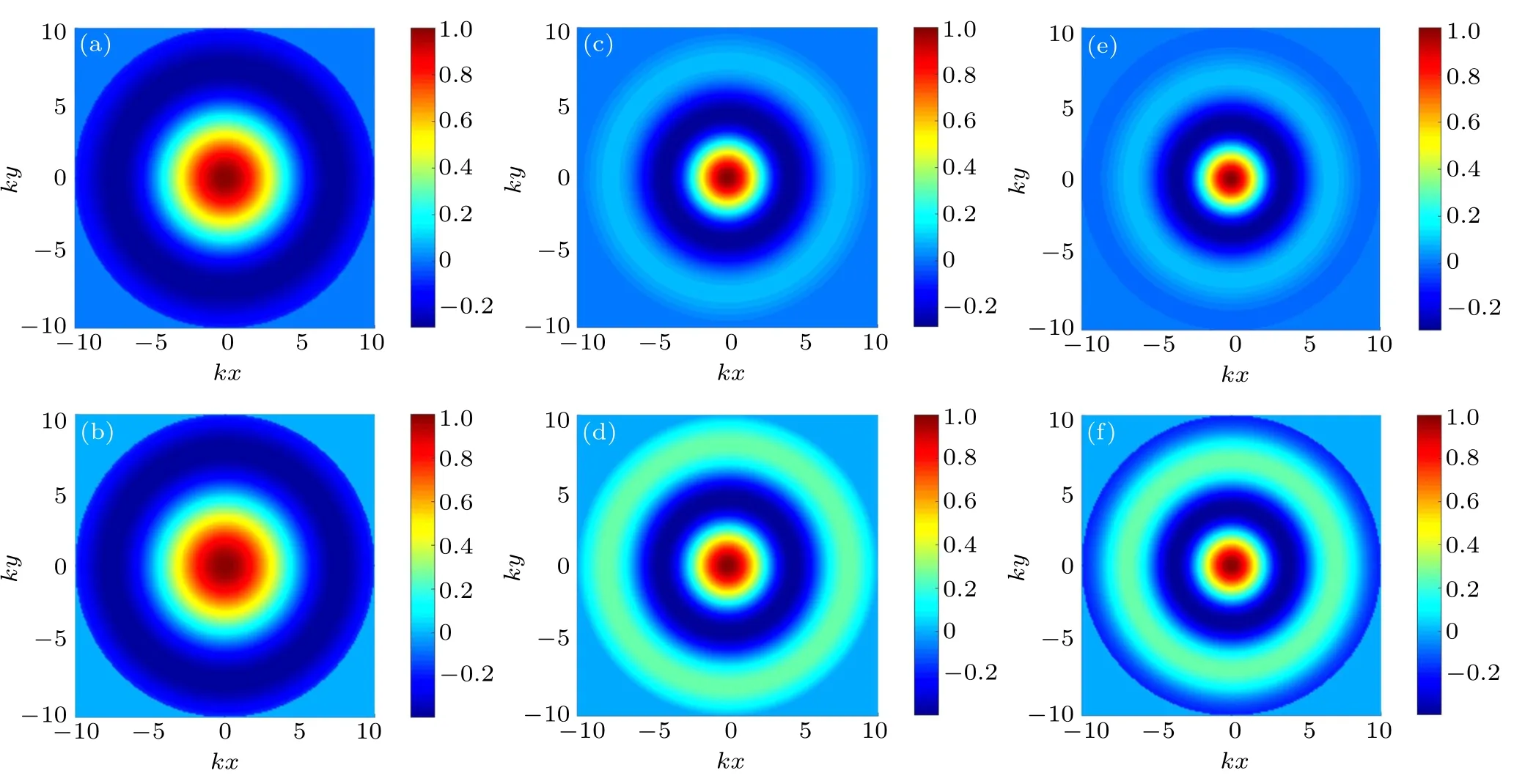
In order to enhance the intuitive understanding of the zero-order quasi-Bessel–Gauss beam,the radial distribution of velocity potential at z=0 with different half-cone angles and beam waists are shown in Fig.2 based on Eq.(3). As can be seen from the plots,increasing the half-cone angle β leads to the decrease of the main lobe width.Moreover,the beam waist W0mainly determines how fast the acoustic energy attenuates in the radial direction. In other words, a smaller beam waist corresponds to a quasi-Bessel–Gauss beam with a stronger focusing characteristic.
According to the finite series expansion theory, the incident wave can be expanded in spherical coordinates with orthogonal properties and finite series properties as[47]

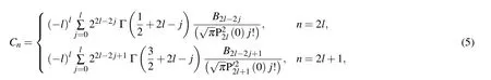
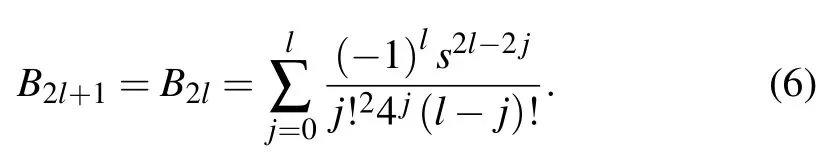
where jnis the n-th-order spherical Bessel function of the first kind,and Pnis the n-th-order Legendre function. The expanding coefficients Cncan be calculated by using the special value method[55]involving expansion with spherical harmonic functions. Substituting n by 2l and 2l+1 for even and odd n,respectively,the coefficients Cncan be expressed as[52]
2.2. Scattering of the incident beam by a spherical shell near the boundary
The reflection wave of the incident beam from the impedance boundary can be expressed in the spherical coordinate system as

where Rs=(Z −ρ0c0)/(Z+ρ0c0)is the reflecting coefficient of the impedance boundary, in which Z is the surface normal acoustic impedance of the medium where the image spherical shell is immersed, ρ0is the mass density of the fluid medium. It is noted that Rs=1 corresponds to the absolutely rigid boundary condition,while Rs=0 corresponds to the unbounded condition.
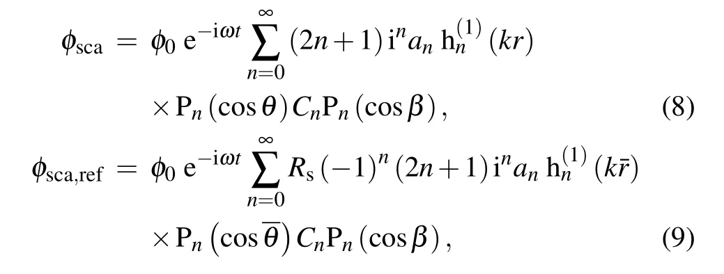
The scattering wave velocity potential of the real and image shell can be respectively expressed as
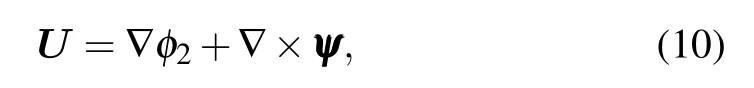
According to the theory of vector analysis, the particle displacement in the coated elastic material can be expressed as the sum of the gradient of a scalar potential and the curl of a vector potential as
where φ2and ψ satisfy the wave equations for the compressional and shear waves filling the elastic material,respectively as

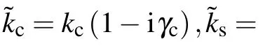
where ∇2denotes the Laplacian operator, kc= ω/ccand ks=ω/csrepresent the compressional and shear wave numbers,respectively. Their wave velocities can be calculated by
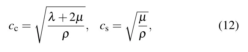
where λ and µ denote the Lame coefficients, ρ is the mass density of the coated elastic layer. Hence, φ2and ψ can be expressed as
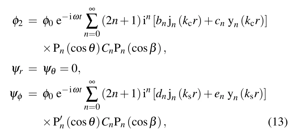
where yndenotes the n-th-order spherical Bessel function of the second kind,bn,cn,dn,enare the coefficients determined by certain boundary conditions.
As for the sound wave in the ideal fluid filling the hollow space,its velocity potential can be written as
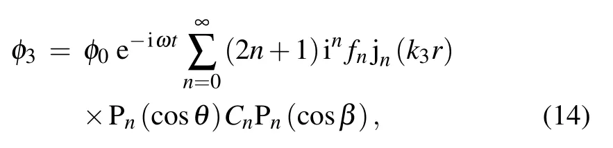
where k3is the wave number in the inner fluid medium.
Obviously, the boundary conditions in this problem are set at both r=a and r=b: (i) The acoustic pressure in the fluid must be equal to the normal component stress in the solid;(ii)The normal component of the displacement must be continuous in the interfaces;(iii)The tangential component of the stress must be equal to zero in the interfaces.
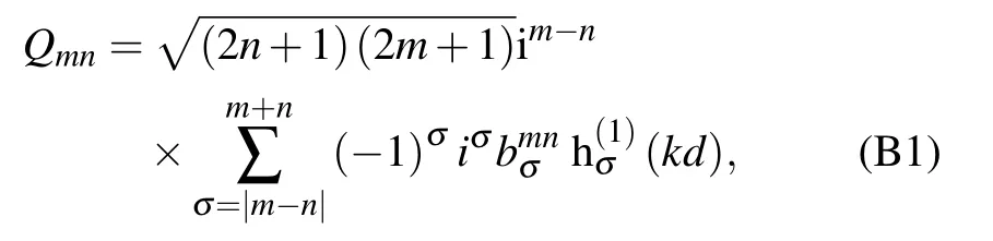
It seems that we can directly work out the problem of acoustic scattering through the boundary conditions above.However,the velocity potentials are expressed in different coordinate systems,presenting a challenge to our computing process.Using the classical form of the translational addition theorem for bi-spherical coordinates,we can express the scattering velocity potential from the image shell in spherical coordinate system(r,θ,φ)as follows:

where the detailed expression of the parameter Qmnis given in Appendix B,which can also be found in Ref.[56].
Equation(15)can also be rewritten in another form as

where

Therefore,the normal velocity and the total sound pressure can be expressed as

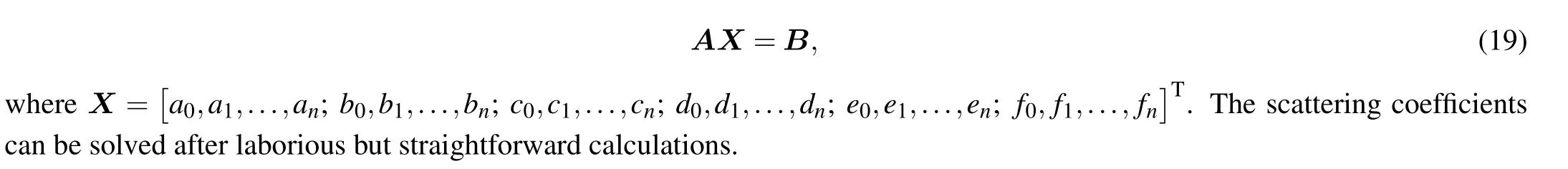
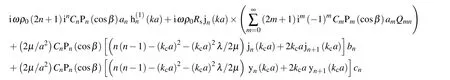
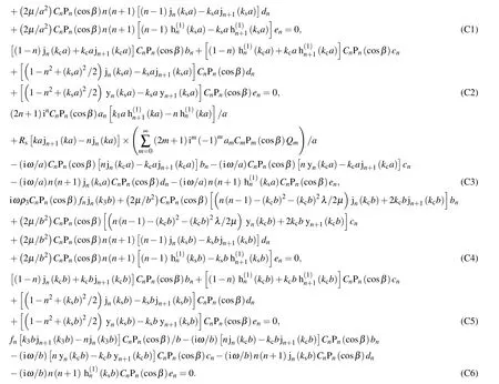
Incorporating Eqs.(13),(14),(17),and(18)into the boundary conditions mentioned above,we can obtain a linear system of equations. The detailed expressions of these equations are presented in Appendix C,thus only a simplified matrix form of them is given here as follows:
2.3. Acoustic radiation force on a sphere near the boundary

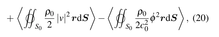

Considering the symmetrical property of this problem,only the axial component of the radiation force acting on the spherical shell needs to be computed. Projecting Eq. (20) in the direction of z axis,we can obtain

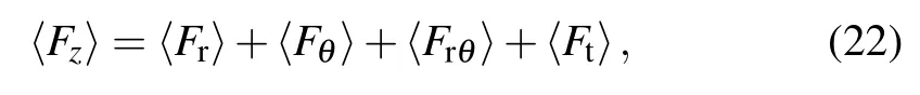
Therefore,the axial radiation force can be expressed by
where
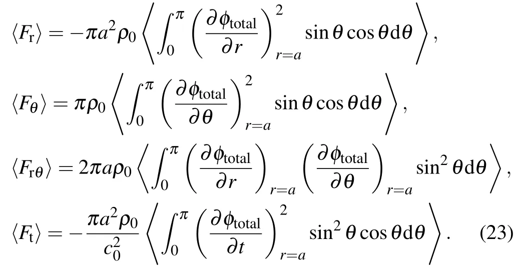
After some mathematical calculations,the radiation force can finally be written in a simplified form as

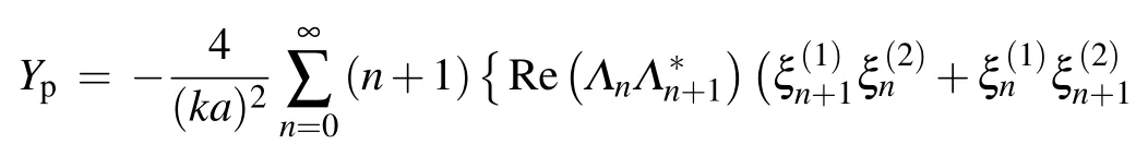

where
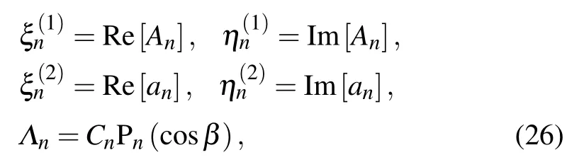
in which Re and Im represent the real and imaginary parts of a complex function,respectively.
3. Numerical simulations and analyses
In order to more clearly illustrate the general behavior of the acoustic radiation force on an elastic spherical shell near an impedance boundary, several numerical simulations are provided in this section. The physical constants of all the materials used in the following simulations are listed in Table 1.Hereafter, the surrounding ideal fluid is assumed to be water.In all of our calculations,the infinite series in Eq.(25)are truncated at|an/a0|∼10−6,which can well balance the accuracy and calculation efficiency.

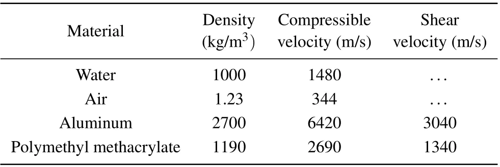
Material Density Compressible Shear(kg/m3) velocity(m/s) velocity(m/s)Water 1000 1480 ...Air 1.23 344 ...Aluminum 2700 6420 3040 Polymethyl methacrylate 1190 2690 1340
3.1. Effects of the impedance boundary on the radiation force
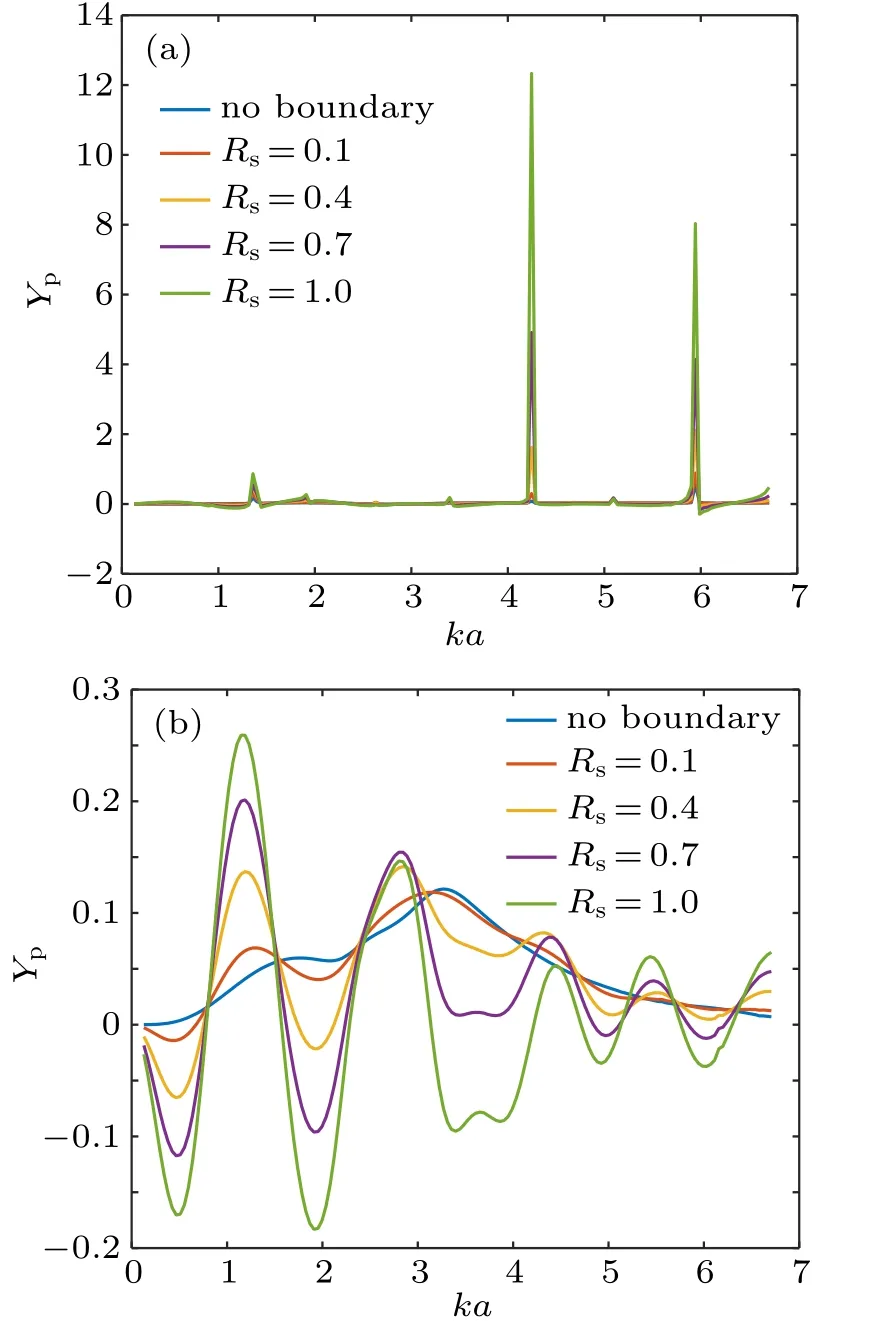
The effect of the impedance boundary on the radiation force function curves for a single elastic spherical shell is discussed in this section. Figure 4 plots the radiation force functions on an elastic shell with b/a = 0.75 and d/a = 2 for a zero-order quasi-Bessel–Gauss beam in the case W0=3λ,β =π/3. The fluid medium within the hollow space is assumed to be water. In Figs. 4(a) and 4(b), the elastic shell is supposed to be made of polymethyl methacrylate(PMMA)and aluminum, respectively, which are two common materials in biomedical ultrasound. The reflecting coefficient of the impedance boundary is set as Rs=0.1,0.4,0.7,and 1.0. For a blood vessel,the reflecting coefficient is estimated to be in the range 0.05∼0.15 according to the measurement for the acoustic impedance of blood vessel walls.[57]However, a variable reflecting coefficient ranging from 0 to 1 is considered in the following calculations to better visualize the effect of changing Rson the radiation force. Also,the case when Rs=0.1 is especially studied. The results for the radiation force function in free space are also provided in the same figure for ease of comparison. In our simulation,the increment step of ka is selected as 0.01 so as to avoid missing the very narrow resonant peaks. Inspection of the results reflects the huge influence of the interface added to the problem. Compared with the results in free space, the radiation force function curves exhibit an obvious oscillatory property. For the case of a PMMA shell,a series of sharp peaks appear in the curves, which may correspond to the resonant frequencies of the elastic vibration in the shell. At these peaks, nearly all the acoustic energy is stored within the shell without leaking into the fluid. However, for an aluminum shell, the high-amplitude peaks disappear. This is mainly due to the larger discontinuity of the acoustic impedance at the water-aluminum interface than the water-PMMA interface,thus less acoustic energy can be transmitted into the elastic material. As the reflecting coefficient Rsincreases,the amplitudes of the peaks will be significantly enhanced. However,the variation of Rsdoes not shift the positions of maxima and minima in the curves. In addition, it is interesting to observe that for both spherical shells, the radiation force can be negative at selected ka values, which is another distinctive property compared with the results in an unbounded fluid medium. This phenomenon means that the shell can be driven towards the sound source, resulting from the reflection wave by the impedance boundary. An explicit explanation of the physical mechanism for the negative radiation force is that the scattering in the forward hemisphere is relatively stronger than in the backward hemisphere, which has been proved in earlier studies on Bessel beams.[17,58]
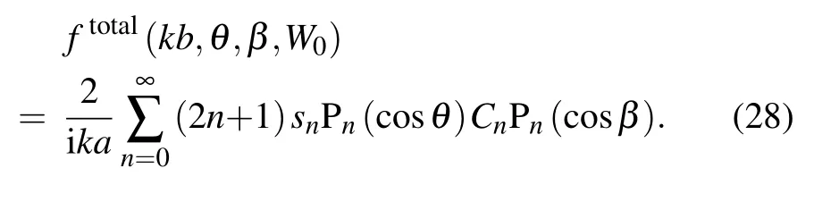
To better understand the features of the acoustic radiation force on an elastic spherical shell for zero-order Bessel–Gauss beams,the total scattering velocity potential in the far-field region can be expressed in the term of form function as

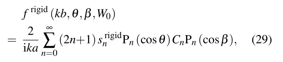
For an absolutely rigid sphere, the form function can be expressed as:

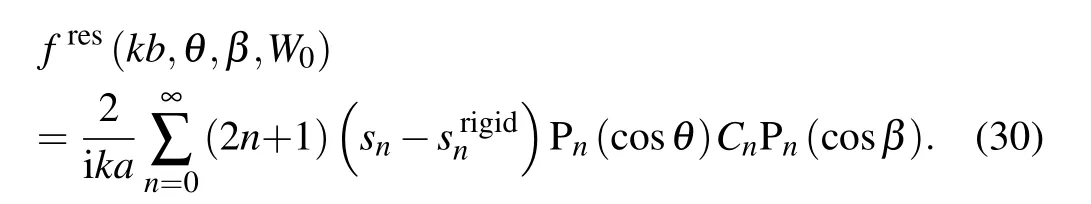
The theoretical discussion above is applied to the PMMA spherical shell in Fig.4(a). The form function moduli of the total, rigid background, and pure resonance back scattering are depicted in Figs. 5(a), 5(b), and 5(c), respectively. It is shown that the rigid background scattering plots oscillate around|f|=1 when ka>2 but do not have any sharp peaks.The oscillations in Fig.5(b) are caused by the interferences between the specular contribution and Franz wave. The difference between the total and rigid background scattering form functions is due to the resonance of different vibration modes,as is clearly shown in the pure resonance backscattering form function plots. It is easy to find that the resonance scattering peaks in Fig.5(c)coincide well with the radiation force function peaks in Fig.4(a), which proves that all of these sharp peaks result from the resonant vibration modes. These resonant vibrations are closely related to the acoustic property of the shell and the surrounding fluid medium(water).

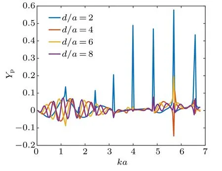
In real applications, the spherical shells are often at various distances from the reflecting interface. Therefore, it is necessary to consider the radiation force functions with different distance-to-radius ratios. With Rs=0.5 and b/a=0.75,the radiation force functions on a water-filled PMMA shell at different d/a values are depicted in Fig.6. Other parameters about the incident beam are set as β =π/3 and W0=3 λ. It is noticeable that the extrema in the figures,corresponding to the resonance vibration modes of the shell,can appear as not only the maxima but also the minima. This phenomenon can also be found in the simulated results for a spherical shell in free space in Ref.[44].As the spherical shell moves away from the boundary, which corresponds to the increase of d/a, the amplitudes of the resonant peaks will decrease obviously at high frequencies. These phenomena prove that the shell–boundary distance is an important factor influencing the radiation force peaks.
To more accurately evaluate the effects of distance-toradius ratio on the radiation force,the Ypversus d/a curves for a water-filled PMMA shell at ka=0.42 in the case of different Rsare shown in Fig.7,which can be regarded as the incidence of a 10-MHz beam upon a micro-shell of outer radius 10µm.All of the other parameters are set exactly the same as in Fig.6.It is easy to find that the peaks and dips are periodically distributed along the d/a axis. As has been found in Ref. [35],when the boundary is absolutely rigid (Rs=1), the radiation force vanishes at pressure nodes(kd =π/2, 3π/2, 5π/2,...)or antinodes(kd=0,π,2π,...)and gets its maximum value at the intermediate locations(kd=π/4,3π/4,5π/4,...).Therefore, the period of the Ypcurves along the d/a axis can be calculated as π/ka=7.48 given that ka=0.42, which consists well with the simulated plots. With the growth of Rs,the amplitude of Ypincreases,consisting well with the conclusion from Fig.4.
3.2. Effects of the shell’s thickness on the radiation force
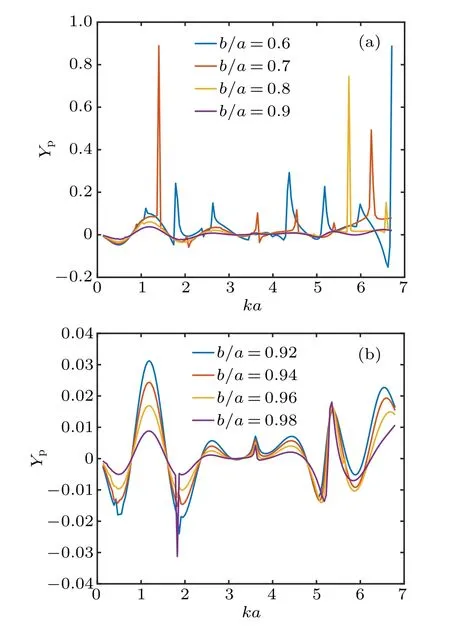
In biomedical ultrasound applications, the drug-loaded micro-shells are often developed with various thicknesses to meet different demands in practice. To evaluate the effect of changing the spherical shell’s relative thickness, the computed results for the radiation force functions on a waterfilled PMMA shell with different relative thicknesses are depicted in Fig.8. With Rs= 0.5, d/a = 2, β = π/3, and W0= 3λ, the two subgraphs (a) and (b) plot the results in the case 0.6 ≤b/a ≤0.9 with increment ∆(b/a) = 0.1 and 0.92 ≤b/a ≤0.98 with increment ∆(b/a) = 0.02, respectively. It is interesting to find in Fig.8(a) that when the coated elastic layer is relatively thick (b/a<0.9), highamplitude peaks emerge at resonant frequencies, which correspond to different ka values with the variation of b/a.However, the resonant peaks disappear in the simulated ka range when the value of b/a reaches 0.9. In fact, with the increase of b/a, the resonant vibration modes shift to high frequencies that are beyond our simulated range. Nevertheless,we are not going to study these peaks considering the severe attenuation of sound energy at high frequencies. The results for thinner shells in Fig.8(b)also exhibit no sharp resonant peaks,while a series of maxima and minima still exist.The increase of b/a leads to the decrease of Ypbut does not influence the positions of peaks and dips. It is also noteworthy that the attractive force can be obtained at appropriate ka and b/a values.
3.3. Effects of the incident beam on the radiation force
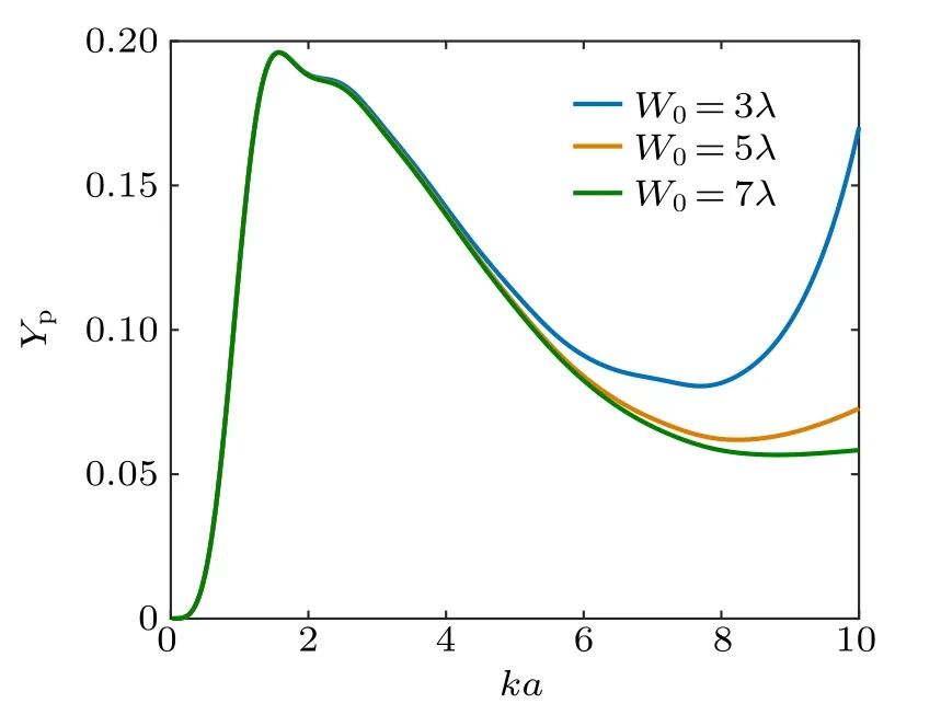
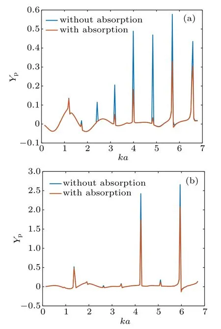
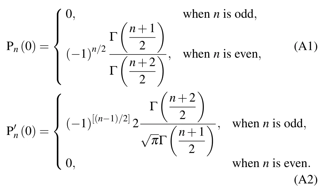
As has been mentioned above,a zero-order quasi-Bessel–Gauss beam is characterized by the half-cone angle β and the beam waist W0. Ypis simulated in the half-cone angle range of 0<β <π/2 with increment 0.01π, as well as in the ka range of 0 It is also noteworthy that taking β =0 for the zero-order Bessel–Gauss beam yields to the results in the basic Gauss beam field. For the case of a PMMA shell, the value of Ypis likely to exceed 70 at selected ka values when β is relatively small. Admittedly, the high peaks in the simulated plots will definitely be damped once the viscosity is considered. However,a theoretical guide can still be provided for acoustic manipulation applications based on these peaks when a strong force is required to push or pull the target particles more easily. As β increases from 0 to π/2, the amplitude of Ypdecreases rapidly at most ka values. It can be expected that the force vanishes at β =π/2 based on the property of Legendre function that Pn(0)Pn+1(0)=0,which is perfectly confirmed by our simulated results. Next,we turn to evaluate how the variation of beam waist affects the radiation force. Unlike the half-cone angle β, the beam waist W0determines the Gauss component of a zeroorder quasi-Bessel–Gauss beam. Figure 10 shows the computed results for a PMMA shell and an aluminum shell in the range of 3λ Gas-filled micro-shells are also very common in the applications of contrast agents, which play an important role in modern drug delivery and imaging systems. Assuming that the shell is filled with air instead of water, the simulated results for a PMMA shell and an aluminum shell with different reflecting coefficients are presented in Figs. 11(a) and 11(b),respectively. The parameters are set as b/a=0.75,W0=3λ,β = π/3, d = 2a, which are exactly the same as those in Fig.4 for ease of comparison. For the case of a PMMA shell, the number of sharp resonant peaks is reduced, but their amplitudes see a pronounced increase.This phenomenon reflects that the change of the interior core material can significantly affect the resonant frequencies. From the view point of manipulating target particles,an air-filled PMMA shell is a preferable choice compared with a water-filled PMMA shell.However, for an aluminum shell, there exists no obvious difference between the radiation force function curves for an airfilled shell and a water-filled shell. This is mainly because that only little energy can enter the interior core due to the serious mismatching of acoustic impedance between the adjacent layers. Therefore,the variation of the material filling the hollow space does not obviously affect the property of radiation force. Based on the image theory and the finite series method,a zero-order quasi-Bessel–Gauss beam has been expanded in terms of harmonic spherical functions. A closed-form expression of the acoustic radiation force on an elastic spherical shell near an impedance boundary for zero-order quasi-Bessel–Gauss beam is derived. On the basis of theoretical results, several corresponding simulated results are also provided. The oscillatory property and the negative radiation force at selected ka values are two main influences of the impedance boundary added to this problem. Some sharp resonant peaks appear in the results for a PMMA shell but not an aluminum shell. With the increase of Rs,high-amplitude radiation force can be obtained,while the positions of maxima and minima remain unchanged. When the shell moves along the beam axis,the radiation force function will vanish at pressure nodes and antinodes and increase to maximum at the intermediate locations. For a PMMA shell, a relatively thick coated layer is conducive to pushing or pulling particles through the strong radiation force. As the two parameters characterizing a zero-order quasi-Bessel–Gauss beam,the half-cone angle and the beam waist can both significantly influence the radiation force. Resulting from the energy focusing effect of the Gauss component, the radiation force function exhibits an obvious increase at small beam waists in the range ka>4. The viscosity of the elastic coated layer leads to the attenuation of sound energy and then the reduction of radiation force peaks at high ka values. In summary,the present work systematically investigated the acoustic radiation force on an elastic spherical shell near the boundary,which can be extended to the drug delivery and imaging in biomedical ultrasound. Appendix B:Expression ofQmn The paprameter Qmnis given by Appendix C:Expressions of Eq.(19) The detailed expressions of Eq.(19)are given as follows: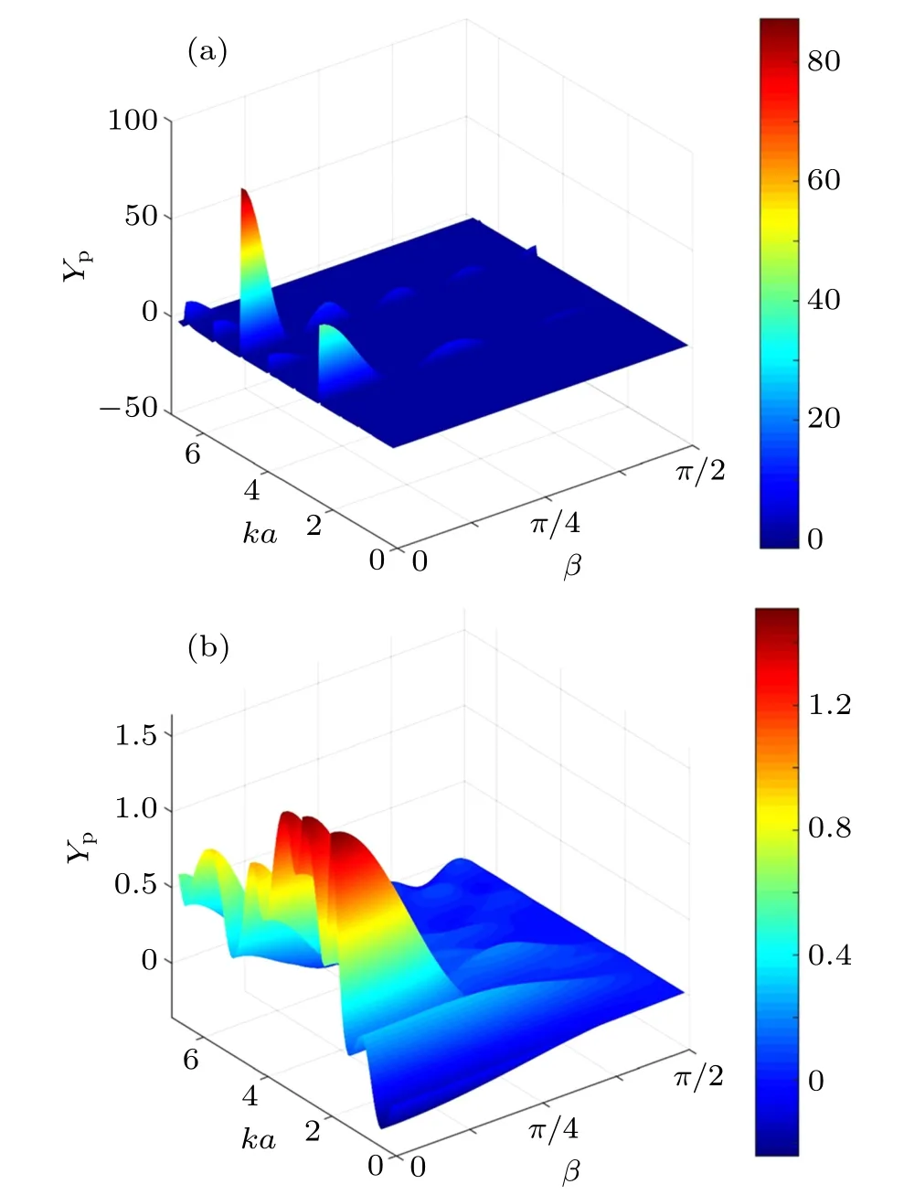
3.4. Effects of the material within hollow space on the radiation force
3.5. Effects of the viscosity on the radiation force
4. Conclusions


猜你喜欢
杂志排行

Chinese Physics B的其它文章
- Speeding up generation of photon Fock state in a superconducting circuit via counterdiabatic driving∗
- Micro-scale photon source in a hybrid cQED system∗
- Quantum plasmon enhanced nonlinear wave mixing in graphene nanoflakes∗
- Restricted Boltzmann machine: Recent advances and mean-field theory*
- Nodal superconducting gap in LiFeP revealed by NMR:Contrast with LiFeAs*
- Origin of itinerant ferromagnetism in two-dimensional Fe3GeTe2∗