Secondary and activated X(γ)radiation of SPHIC particle therapy facility
2021-05-06WeiMingSunNingDuWenDongTianLanWang
Wei-Ming Sun· Ning Du · Wen-Dong Tian· Lan Wang
Abstract We report the secondary X(γ)radiation from the accelerator in a normal operating state and activated X(γ)radiation from the accelerator devices when the accelerator stops operating in the cancer treatment facility of the Shanghai Proton and Heavy Ion Center (SPHIC). These radiation measurements show us the structural radiation distribution along the beam lines and devices inside the accelerator room when the beam is on and off and can support the radiation protection design of the accelerator facility used for cancer treatment and help evaluate the accumulated radiation dose in the case of an emergency,such as a personal safety system failure or a radiation accident. The radiation dose rate measured in this facility shows that the facility is safe from the radiation protection point.After shooting the quality assurance(QA)beam,the radiation dose rate in the treatment room was also measured to investigate the radiation dose space distribution and decay time dependence. In addition, the time period before safely entering the treatment room after determining the shooting of the QA beam is recommended to be approximately 5 min.
Keywords Secondary radiation · Activated radiation ·Nuclear safety and radiation protection · Dose rate ·Accelerator
1 Introduction
With the development of nuclear and high-energy physics applications in industrial and medical therapy, ion therapy was proposed and investigated in the Berkley Lawrence National Laboratory by applying unique physical properties,i.e.,a Bragg peak at the end of the range[1].In addition,in 1990,the first clinical accelerator providing a proton beam was built for cancer therapy in the Loma Linda University Medical Center (LLUMC). Benefiting from the research conducted at LLUMC, several clinical proton therapy facilities [2] and centers have been organized, improving and promoting the rapid development of proton treatment studies [3, 4]. Heavy ions have identical Bragg peak-like protons; therefore, heavy ion cancer therapy studies and treatments were later started in NIRS(Japan) and GSI (Germany) [5]. There are almost 100 ion therapy centers currently in operation or under development around the world, and more than 100,000 patients have benefited from proton and heavy ion treatments[6,7].More than 3000 patients have been treated at the Shanghai proton and heavy ion center (SPHIC), the first heavy ion therapy center in China, which started operation and treatment in May 2015. An increasing number of ion therapy facilities require an increasing number of occupational doctors, medical physicists, clinical therapists,engineers, and nurses involved in clinical therapy, treatment planning systems (TPSs), facility operation, and maintenance.Although high-energy ions generated from an accelerator can kill a tumor, they also produce secondary radiation and activation when the ion beam hits the beam transport lines, devices, air, walls, and patients [8].Harmful to humans, radiation protection is extremely important and mandatory, from the accelerator design to patient treatment[9,10],and concrete shielding is the main measure used to protect the public and occupational operators from radiation [11]. Because occupational operators are close to the facility, they may receive more radiation than the public. Radiation levels can help us propose reasonable radiation protection guidelines and regulations and adopt proper methods to improve the quality of radiation protection. To minimize the absorbed radiation and evaluate the exposed radiation dose in the case of an emergency, simulation and measurement studies have been conducted, including the shielding design [2, 12–14],exposed radiation dose of clinical physicians [15, 16],calculation of the air activation caused by a proton accelerator [17], and neutrons produced from a beam [18, 19].The major purpose of radiation protection studies is to increase the radiation safety of the accelerator and beam and reduce the personal dose of the operators [6, 20]. In this study, the secondary and activated X(γ) dose rate generated from the SPHIC accelerator under normal operation is measured, the beam loss distribution along beam lines from the secondary and activated X(γ)radiation dose rate is analyzed, and the radiation safety during operation and maintenance of the SPHIC accelerator is evaluated. The activated X(γ) radiation decay after a QA beam is applied in the treatment room was also measured,and a safety period for entering the treatment room after QA beam irradiation is recommended.
2 Accelerator in SPHIC
The SPHIC accelerator consists of seven main sections,as shown in Fig. 1: (1) ion sources (IS), which generate 8 keV/u protons and carbon ions, (2) a low-energy beam transportation(LEBT),which transports ions from the IS to the linear accelerator (Linac), (3) Linac, where the ion energy is accelerated from 8 keV/u to 7 MeV/u, (4) a medium energy beam transportation (MEBT), which transports ions from the Linac to the Synchrotron(SYNC),(5) a SYNC, which accelerates ions from 7 MeV/u to the requested energies(the maximum energy is 221 MeV/u for protons and 430 MeV/u for carbon, and the equivalent water depth at the maximum energy is 310 mm for both ions), (6) a high-energy beam transportation (HEBT),which transports high-energy ions extracted from SYNC to the treatment rooms, including a common HEBT part H0 and room sections Hx from H0 to the treatment rooms(TRx), and (7) the treatment rooms (TRx), where three of the rooms have a fixed horizontal beam and one has a 45°semi-vertical fixed beam. The accelerator in SPHIC provides both proton and carbon scanning pencil beams [21],the beam performances of which are summarized in Table 1. As a medical treatment accelerator, more safety aspects are considered and integrated in this machine than in industrial and research machines.The Siemens PT onsite service team is responsible for the operation and maintenance of this facility. The SPHIC PT facility started beam commissioning in 2013, a clinical trial at the end of 2014,and official clinical treatment from May 2015.
3 Detectors used in dose measurement
Two types of radiation dose measurement detectors were used in this work.A scintillation detector was used to measure the transient radiation, and a semiconductor detector was used to measure the accumulated radiation.In normal accelerator operation with the beam, there is no access to the beam transportation line; the semiconductor detectors are fixed on the measurement positions for a limited time, the accumulated dose can be read afterward,and the average radiation dose rate can be calculated from the accumulated dose and measurement time. When the beam is off, free access is provided to the beam transportation line, and the scintillation detector can be used to measure the transient activated radiation dose rate around the beam transportation line. The semiconductor detectors we used here are ‘‘RAD-60S’’ and ‘‘ALOKA PDM-122-SH,’’ which are alarming electrical personal dosimeters(EPDs) and are used for accumulated radiation dose monitoring; the scintillation detector used here is an‘‘Automess 6150 AD 5/H’’and is used to measure only the transient radiation dose rate. All detectors are calibrated,and the details of the detector are listed in Table 2.
4 Secondary and activated X(γ) radiation measurement in accelerator area
An accelerator operation can be identified in two states:‘‘Beam on’’ and ‘‘Beam off.’’ ‘‘Beam on’’ indicates the normal clinical time, during which the beam is present in the accelerator beam lines without a lengthy interruption.‘‘Beam off’’ means there is no beam in the accelerator beam lines for a lengthy amount of time when the beam is stopped.Both secondary and activated X(γ)radiation occur when the beam is on.When the beam is off,the secondary radiation decays rapidly, and only the activated X(γ)radiation can be detected.
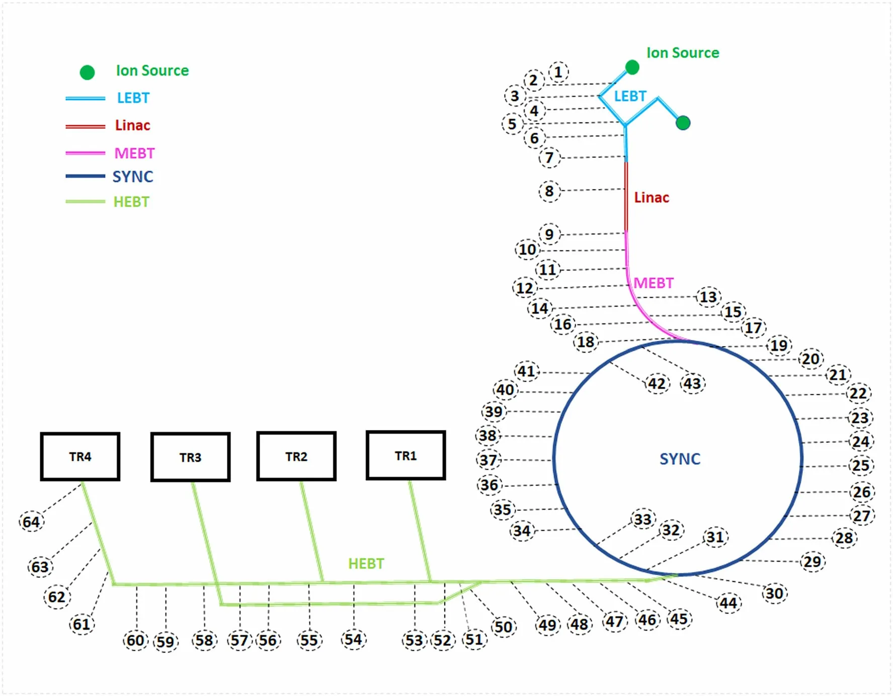
Fig. 1 (Color online) Accelerator layout in SPHIC (different bold lines/colors represent IS (at the top), LEBT, Linac, MEBT, SYNC,HEBT (lower left), and treatment rooms (TRx), respectively. The numbers around the circle and the dashed line indicate the measurement positions along the beam line

Table 1 SPHIC accelerator beam performance
The accumulated secondary and activated X(γ)radiation levels are measured by nine semiconductor dosimeters when the beam is on. The dosimeters are fixed on the surface of the beam vacuum tube, which are marked in Fig. 1 (marker serial numbers from 1 to 64). These measurement positions were uniformly distributed along the beam line,and the device layout and distribution were also considered.The radiation measurement time was more than 24 h to cover one complete clinical day at every measurement position, and there are some repetitive measurements in some measurement positions to check the consistency of the dosimeters and the measured radiation dose. Then, average dose rate is calculated from the accumulated dose divided by the measurement time to show the average X(γ) radiation dose rate because the average dose rate is a value independent of time and can be compared directly with that of a ‘‘beam off’’ case. Only activated X(γ)ray radiation can be detected when the beamis off. In this case, the transient radiation dose rate is measured instead of the accumulated dose,the scintillation detector is used, and the measurement positions are same as the ‘‘beam on’’ case marked in Fig. 1.

Table 2 Detector function and performance
To compare the radiation dose rate with natural environment, the radiation dose rate in an office is also measured by the detectors ‘‘RAD-60S,’’ ‘‘PDM-122-SH,’’ and‘‘Auotmess 6150 AD 5/H.’’ The office is located on the second floor of the accelerator hall and is a daily working place for accelerator engineers. The radiation level in this office is labeled the ‘‘background’’ because it indicates the environment radiation level for the daily work under the occupational dose rate.The measured background radiation dose rate was consistent and averaged 0.11 μSv/h for the three different detectors. This background radiation dose rate is also consistent with the data in the annual monitoring report of SPHIC [22], the normal official in-room dose rate in the work area and environment of the SPHIC,which is lower than the dose rate close to the accelerator facility and clinical treatment room. This background dose rate is consistently shown in the figures in this paper as a reference radiation level.
Figure 2 shows the average dose rate when the beam is on. The numbers of the x-axis indicate the labeled measurement positions in Fig. 1: measurement positions 1–7 are locate in the LEBT section, 8–18 are located in the Linac and MEBT section, 19–43 are around the synchrotron accelerator ring, and 44–64 are in the HEBT section.

Fig. 2 (Color online) Average X(γ) dose rate (round symbols) along the SHPIC beam lines when the beam is on (measurement point markers are plotted in Fig. 1, and the dashed line is the background radiation dose rate as a reference)
In the LEBT section,the particle energy is 8 keV/u from the ion source, and low-energy ions protected by the beam vacuum tube do not activate any radiation. Therefore, the radiation dose rate measured in the LEBT section is below the background level. The first peak of the radiation dose rate is located at around measurement position No. 8.Measurement position No.7 is before the Linac,where the DC beam cuts into the macro-pulse beam, and 95% of the cut beam is dumped at around No.7.No.8 is at the exit of the radio frequency quadrupole accelerator (RFQ) in the Linac section.The ions are accelerated to 400 keV/u in the RFQ, and the RFQ transmission rate is only 50%. In addition,ion dumping before and in the RFQ produces the first radiation peak at measurement position No. 8. The ions are then sped up to 7 MeV/u in the Linac before being injected into the synchrotron.
The highest broad radiation peak with the measured maximum radiation occurring at a rate of 1 mSv/h from measurement positions 19–30 covers the beam injection,extraction,and synchrotron beam dumping.This broad and high peak indicates the greatest possibility of beam loss caused by these activities. From measurement positions 30–43,on the opposite half side of the synchrotron ring,the radiation dose rate is 2 orders lower than on the other half side,because in this half ring there only beam acceleration activity occurs, and less of the beam is lost. Following measurement position 44 is the HEBT section, where a mid-level radiation emission rate of around several μSv/h,and a peak at around position 48,occurs.In this section,the beam loss is caused by dumping at position 48 after a synchrotron and beam abort treatment. A valley with a radiation dose rate of less than 0.1 μSv/h from measurement positions 56–61,which are in the common HEBT line H0 between TR1 and TR4, indicates that the beam optics are well designed in this region, the beam is perfectly constrained,and beam loss rarely occurs within this range.In Fig.2 the reference line(black dash line)is also plotted to show the background radiation dose rate and the dramatic difference in radiation level.
The secondary radiation directly from the beam loss disappears after the beam stops and can only irradiate people in the case of an incident such as a PSS failure or emergency, because the accelerator area is normally inaccessible through PSS protection. Radiation from the activation may exist for an extremely long time after the beam stops. It can irradiate people who are working in this area,such as occupational engineers and maintenance workers.It is the main source of occupational irradiation, and this part is the most important and monitored radiation within the facility environment. In Fig. 3, both secondary and activated radiation dose rates are plotted for beam-on(blue round symbols) and beam-off (red square symbols) cases,respectively, and both dose rates are measured on the surface of a beam vacuum tube.The activation dose rate is much lower than that of the beam on, the activation dose rate is below the background level at most measurement positions along the beam line, and the activated radiation peak appears only in the region where the strongest secondary radiation occurs. This consistency reveals that the activation radiation is caused by the beam loss on the beam line components,but the activated radiation is much lower than the secondary radiation during a beam on. After the beam stops, the maximum existing activated dose rate is less than 1 μSv/h on the synchrotron ring where injection,beam dumping, and extraction activities are included,whereas the other parts have identical background dose rates as found in the office, and most are even lower.

Fig. 3 (Color online) Averaged X(γ) dose rate along SHPIC beam lines when beam is on (blue round symbols) and off (red square symbols). The measurement point markers are plotted in Fig. 1, and the dashed line is the background radiation dose rate as a reference)
The activation dose rate is also measured at positions 1 m away from the beam line when the beam is off, where most likely operators and engineers pass through. To analyze the activated radiation space distribution and averaged/overall environmental radiation dose rate, the measured dose rates are plotted in Fig. 4, and all data are measured 1 h after the beam stops. There is a slight radiation peak matching with the dose rate peak on the beam line tube surface when the beam is on and off, indicating that the activated radiation from the beam line is the main X(γ) ray source around this location. At around the radiation peak locations,the dose rate 1 m away from the beam line is much lower than that on the beam line surface.This reveals that ‘‘increasing the distance from the source decreases the exposed radiation’’under radiation safety and protection strategies.
One can also note that at most measurement positions,the activation radiation dose rate on the beam line surface is approximately 20%less than dose rate of the background radiation, and less than the dose rate measured at the measurement points at 1 m away from the beam line,which is caused by the shielding effect of the beam line tube and all other devices, such as the magnets. This type of shielding effect can also be observed from the radiation dose measurements in the following treatment room.
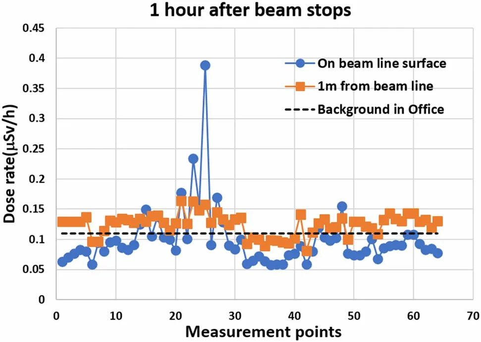
Fig.4 (Color online)Activated X(γ)dose rate on the beam line tube surface and along the route at 1 m outside the beam line and 1 h after the beam stops. Blue round symbols are on the beam vacuum tube,and red square data are measured 1 m from the beam line
There is only one clear activated X(γ)radiation peak on part of the synchrotron ring, arising mainly from a highenergy beam loss, the dose rate of which is much lower than that of a beam on.
5 Secondary and activated X(γ) radiation in treatment room
Radiation in the treatment room is another aspect that influences the personal dose equivalent of the occupational engineers, medical physicists, and therapists. The secondary and activated X(γ) radiation distribution in space and time and its measurement can reveal the transient and activated X(γ) radiation level in the treatment rooms.
This measurement adopts the layout for a daily beam quality check,as shown in Fig.5.A multiwire proportional chamber (MWPC) is placed on the beam iso-center. (This QA MWPC is equivalent to a water thickness of 260 μm[23, 24]. There are two carbon fiber-protecting plates on the MWPC beam entry and exit window; the thickness of the beam entry protection plate was 0.65 mm, and the thickness of the beam exit window protection plate was 1.05 mm). The beam passes through the MWPC and then hits the wall along the beam direction and consists of concrete and an iron plate [11, 12]. Figure 5 shows the testing device layout in the treatment room, MWPC, and measurement detector positions. The light-red cross on the MWPC marks the beam iso-center,to which the MWPC is aligned, and the dark-red cross on the wall marks the downstream beam hitting position on the wall. The orangerectangles mark four X(γ) detector measurement positions when the beam is on, and the activated X(γ) radiation is also measured at these four predefined positions.

The definition of the treatment room coordinates is shown by the green arrows in Fig. 5, where +x is horizontally to the right along the beam direction,+y indicates the downward direction vertically, and +z is the beam downstream direction. The beam outlet is located at the bottom left corner in Fig. 5, and the beam is emitted from the outlet, passes through the MWPC (and the iso-center)and finally hits the wall. The iso-center is defined as(0 cm, 0 cm, 0 cm),and the beam spot hitting the wall is at(0 cm, 0 cm, 400 cm). Four dosimeters were fixed at the positions with the coordinates listed in Table 3 to measure the accumulated X(γ) dose from the ion irradiation.


Table 3 Dosimeter position (coordinates) and accumulated X(γ)radiation dose in carbon beam irradiation

6 Summary
We measured the X(γ) rays from the secondary and activated radiation when the SPHIC accelerator beam was on and off. There is strong secondary X(γ) radiation when the beam is on during clinical treatment,and the maximummeasured dose rate value is 1 mSv/h on some parts of the beam line. In addition, there is a structural dose rate distribution based on the beam lattice and optics. Secondary and activated X(γ) radiation mainly comes from the highenergy beam loss. The results provide a reference for the radiation level inside the accelerator hall when the beam is on. This can help us estimate the irradiated and accumulated dose in cases of an incident or emergency, evaluate any injuries, and follow up with medical treatment if needed.It is also helpful to update the radiation protection regulations and recommendations on-site.

Table 4 Residual X(γ)dose rate(μSv/h)after QA beam in treatment room
After the beam stops, the residual radiation from the activation is low,and the distribution of activated positions is consistent with the secondary radiation and beam loss location with the beam on. The measured activated radiation data show that SPHIC is extremely safe from the viewpoint of nuclear safety and radiation protection.
The radiation measurement results of the treatment room after the QA beam showed residual radiation after the QA beam hit the wall without dumping,and the amount of time before safely entering the treatment room was 5 min after the QA beam is applied. QA beam dumping in the treatment room is used to avoid the beam hitting the wall directly, which produces strong secondary and residual radiation. Although radiation can be detected after the beam is applied in the treatment room,the area outside the treatment room is safe because of the designed shielding of the concrete wall [12, 22].
AcknowledgementsAll authors contributed to the study conception and design. Material preparation, data collection and analysis were performed by Wei-Ming Sun, Ning Du, Wen-Dong Tian and Lan Wang. The first draft of the manuscript was written by Wei-Ming Sun, and all authors commented on previous versions of the manuscript. All authors read and approved the final manuscript.
杂志排行
Nuclear Science and Techniques的其它文章
- Proton linac-based therapy facility for ultra-high dose rate(FLASH) treatment
- Design of a personnel safety interlock system for proton therapy
- Investigation of ex-vessel core catcher for SBO accident in VVER-1000/V528 containment using MELCOR code
- Development of a seven-cell S-band standing-wave RF-deflecting cavity for Tsinghua Thomson scattering X-ray source
- Analysis of influencing factors on the method for determining boron concentration and dose through dual prompt gamma detection
- Sinogram denoising via attention residual dense convolutional neural network for low-dose computed tomography